DMP Electronics 7800 Series Installation And Programming Manual
Graphic touchscreen keypad
Hide thumbs
Also See for 7800 Series:
- Installation and programming manual (52 pages) ,
- Installation and programming manual (60 pages) ,
- Quick start manual (2 pages)
Table of Contents
Advertisement
Quick Links
Advertisement
Table of Contents

Related Manuals for DMP Electronics 7800 Series


Summary of Contents for DMP Electronics 7800 Series
- Page 1 INSTALLATION AND PROGRAMMING GUIDE 7800 Series Graphic Touchscreen Keypad...
-
Page 2: Table Of Contents
CONTENTS Get Started ......... 1 Arming/Disarming Wait Time ....10 Card Options ..........10 Model-Specific Features ........1 Require Site Code ..........11 What’s Included .............1 Number of User Code Digits ....12 What You’ll Need ..........1 No Communication with Panel ....12 Procedure ..............1 System Type ............12 Install the Keypad ...... - Page 3 Reference .........20 Keypad Bus Wiring Specifications .....20 Requirements for Listed Installations ..20 Compatibility ............21 Public Card Formats ........21 Readers and Credentials ......21 Ordering Information ........22 Keypads ............22 Accessories ............22 Specifications ........23 Certifications ........23 Underwriters Laboratory (UL) Listed ..23 FCC Information ..........
-
Page 4: Get Started
GET STARTED 7800 Series Graphic Touchscreen Keypads offer an easy to use touchscreen interface, optional panic keys, an AC Power/ Armed LED, an internal speaker, a simple terminal connection to a 4-wire keypad bus, and other model-specific features. Keypads can be mounted in a conduit or backbox, or on a flat surface with appropriate fasteners. -
Page 5: Install The Keypad
INSTALL THE KEYPAD Remove the Cover To see how to remove the cover, watch the video How to Open a Touchscreen Keypad. The keypad housing is made up of two parts: The cover, which contains the circuit board and components, and the base. When removing the Cover cover, refer to Figure 1. -
Page 6: Wire The Keypad
Wire the Keypad To wire the keypad, make the connections shown in Figure 3. To wire external readers to the keypad, make the connections shown in Figure 4 and Figure 5 as required for your installation. Caution: Disconnect all power before wiring. Failure to do so may result in equipment damage or injury. Observe polarity when making power connections. - Page 7 WIRE COLOR PURPOSE WIRE COLOR PURPOSE Black Ground from Panel* Violet Door Strike, NC Green Receive Data from Panel* Gray Door Strike, C Yellow Send Data from Panel* Orange Door Strike, NO Power from Panel* White/Brown Zone 1 Black Ground to Reader White/Red Zone 2 Power to Reader...
-
Page 8: Optional: Wire For Access Control
Optional: Wire for Access Control Internal Access Control Reader 7873/7873H and 7872 keypads provide a built-in proximity card reader that is compatible with most standard 125 kHz proximity credentials. An external 13.56 MHz proximity reader can be connected and will be compatible with 13.56 MHz proximity credentials. -
Page 9: Use The Keypad
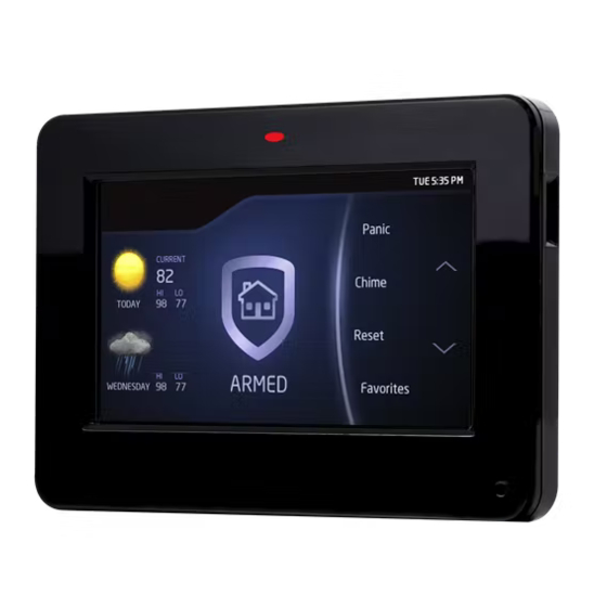
USE THE KEYPAD Keypad Layout Armed/Power LEDs & Proximity Reader Dealer Logo microSD Card Slot Interactive Arming/ Disarming Press the Home Shield Navigation Arrows or touch and drag the menu to scroll Local Weather Carousel Menu Figure 6: Keypad Layout Enter Characters To see how to enter characters, watch the video How to Type on a Keypad. -
Page 10: Program The Panel
PROGRAM THE PANEL Before continuing with programming and setup, you’ll program the keypad in the panel as a device. To access the Programmer menu, reset the panel, press Keypad in the carousel menu, enter 6653 (PROG), then press CMD. After completing each of the following steps, press CMD to advance to the next option. Refer to the panel programming guide as needed. -
Page 11: Program The Keypad
PROGRAM THE KEYPAD Refer to the appropriate panel programming guide as needed. Keep in mind that operation for some programming options is restricted to the appropriate model. To access the Keypad Options menu, press Options in the carousel menu. Press the Installer Options wrench icon, enter 3577 (INST), then press CMD. KEYPAD OPTIONS KPD KPD OPT DIAG... -
Page 12: Activate Zone 3 Request To Exit
Zone 2 Bypass Time ZONE 2 BYPASS Enter the number of bypass seconds to elapse before the bypass timer expires. Range is TIME: 20-250 seconds. Press any select area to clear the keypad display and enter the number of seconds. Default is 40 seconds. 10 seconds before 5 Second the bypass time expires,... -
Page 13: Arming/Disarming Wait Time
Arming/Disarming Wait Time ALL? NO YES DELAY: Select the number of seconds (1-9) the keypad should wait to arm and disarm when an area system displays ALL? NO YES or an H/S/A system waits during arming only. If a selection is not made before the delay expires, the keypad automatically selects YES or AWAY. -
Page 14: Require Site Code
Wiegand Code Length WIEGAND CODE LENGTH: When using a custom credential, enter the total number of bits to be received in Wiegand code including parity bits. Press any select key or area to enter a number between 1-255 to equal the number of bits. -
Page 15: Number Of User Code Digits
Number of User Code Digits NO OF USER CODE DIGITS: The keypad recognizes user codes from 4-12 digits long. Press any top row select key or area to enter a user code digit length. This number must match the user code number length being programmed in the panel. -
Page 16: Dealer Info
Dealer Info DEALER INFO DELETE Select ADD at the DEALER INFO prompt to include information about the dealer when the logo is pressed. The keypad displays ADDING INFO SURE? to confirm the selection. Press YES to proceed. Adding Info Sure? While the info is being uploaded to the keypad, the keypad displays ADDING INFO ADDING INFO. -
Page 17: Select Language
Select Language Select Language allows you to select the language for text on the home screen, the carousel menu screens, and some programming screens. Press a box to select a language and a check mark displays. Press that box again to deselect that option. Only one language can be selected at a time. -
Page 18: Test The Keypad
TEST THE KEYPAD Test the keypad to ensure keypad lighting, individual shortcut keys, and any programmed zones work properly. Access the Keypad Diagnostics menu by pressing Options in the carousel menu. Press the Installer Options or wrench icon and enter 3577 (INST) and press CMD. KEYPAD DIAGNOSTICS KPD KPD Press the select area for KPD DIAG. -
Page 19: Train Your Customers
TRAIN YOUR CUSTOMERS This section contains instructions on how users can arm and disarm their system, use access control, and entry delay. All of the examples displayed assume that CLOSING CODE is YES in panel programming. For more information about using your system, refer to the appropriate system user guide. Access the User Menu In the Carousel Menu, select Keypad. -
Page 20: Use Access Control
Use Access Control Access an Area with a Door Strike If the Door Strike Relay was wired and programmed at the keypad, present a credential to the proximity reader. Once the system validates the card, the Door Strike Relay activates. See Figure 17. System Armed System Ready Panic... -
Page 21: Change System Wi-Fi Password
Change System Wi-Fi Password When you change your network’s Wi-Fi password, the system detects that the password has changed and asks you to update it. To close the Incorrect WiFi Password dialog and return to the main menu, tap the Shield icon. To reopen the dialog from the main menu, tap the Wireless icon. -
Page 22: Icons
Icons Arming Shield Icons Quick Arm Armed Alarm Home Sleep Away Perimeter All System Burglary Fire Ready To Exit Exit Timer Popups Menu Enter Code Arm Instant Attention List Alert Home Installer Navigation Edit Clean Screen Arming Options Panic Options Home Sleep Away... -
Page 23: Reference
REFERENCE Keypad Bus Wiring Specifications ▶ DMP recommends using 18 or 22-gauge unshielded wire for all keypad and AX-Bus/LX-Bus circuits. Do not use twisted pair or shielded wire for AX-Bus/LX-Bus and Keypad Bus data circuits. All 22-gauge wire must be connected to a power-limited circuit and jacket wrapped. ▶... -
Page 24: Compatibility
Compatibility ▶ XT30/XT50 Series Panels ▶ XR150/XR550 Series Panels Public Card Formats WIEGAND SITE CODE SITE CODE USER CODE USER CODE USER CODE CARD FORMAT CODE LENGTH POSITION LENGTH POSITION LENGTH DIGITS H10301 26 BIT H10302 37 BIT W/O H10304 37 BIT W/FAC FARPOINTE 39 BIT CORPORATE 1000... -
Page 25: Ordering Information
Ordering Information Keypads 7872-B Graphic Touchscreen Keypad (black, 4 zones, prox reader) 7872-W Graphic Touchscreen Keypad (white, 4 zones, prox reader) 7872-W/DEMO 7872 Demo Keypad (white) 7873-B Graphic Touchscreen Keypad (black, 4 zones, prox reader, relay) 7873-W Graphic Touchscreen Keypad (white, 4 zones, prox reader, relay) 7873H-W High Security Graphic Touchscreen Keypad (white, 4 zones, prox reader, relay) Accessories... -
Page 26: Specifications
SPECIFICATIONS Operating Voltage 12 VDC Dimensions 5.8” W x 4.135” H x 0.6” D CERTIFICATIONS ▶ California State Fire Marshall (CSFM) ▶ FCC Part 15 RFID Reader FCC ID: CCKPC0131 ▶ Industry Canada ID: 5251A-PC0131 Underwriters Laboratory (UL) Listed ANSI/UL 294 Access Control System Units ANSI/UL 365 Police Connected Burglar...
Need help?
Do you have a question about the 7800 Series and is the answer not in the manual?
Questions and answers