DMP Electronics Thinline Series Installation And Programming Manual
Hide thumbs
Also See for Thinline Series:
- Installation manual (41 pages) ,
- Installation and programming manual (24 pages) ,
- User manual (2 pages)
Table of Contents
Advertisement
Advertisement
Table of Contents

Subscribe to Our Youtube Channel
Related Manuals for DMP Electronics Thinline Series


Summary of Contents for DMP Electronics Thinline Series
- Page 1 INSTALLATION AND PROGRAMMING GUIDE 7000 Series Thinline™ and Aqualite™ Keypad...
-
Page 2: Table Of Contents
CONTENTS Certifications ........19 Get Started ......... 1 Underwriters Laboratory (UL) Listed ..19 What’s Included .............1 FCC Information ..........20 What You’ll Need ..........1 Industry Canada Information .......20 Procedure ..............1 Keypad Features ..........2 Enter Characters ..........3 Panic Key Options ..........3 User Options Menu .......... -
Page 3: Get Started
GET STARTED Thinline™ Series and Aqualite™ Series LCD keypads offer flexible features and functionality. Each keypad provides: ▶ Custom 16-character home or business name in the display ▶ Four 2-button panic keys ▶ AC Power/Armed LED ▶ 32-character display ▶ Backlit keyboard and DMP logo ▶... - Page 4 INSTALL THE KEYPAD Remove the Cover The keypad housing is made up of two parts: the cover, which contains the Cover circuit board and components, and the base. When removing the cover, refer to Figure 1. Base To separate the keypad cover from the base, insert the flat tip of a slotted screwdriver into one of the slots on the bottom of the keypad, then press in slightly to disengage the tab and pry open.
- Page 5 WIRE COLOR PURPOSE WIRE COLOR PURPOSE Black Ground from Panel* Violet Door Strike, NC Green Receive Data from Panel* Gray Door Strike, C Yellow Send Data from Panel* Orange Door Strike, NO Power from Panel* White/Brown Zone 1 Black Ground to Reader White/Red Zone 2 Power to Reader...
- Page 6 Wire for Access Control (Optional) Internal Access Control Reader The 7063/A, 7073/A, 7163, and 7173 keypads provide a built-in proximity card reader that is compatible with most standard 125 kHz proximity credentials. An external 13.56 MHZ proximity reader can be connected and will be compatible with 13.56 MHz proximity credentials.
- Page 7 Normally Closed Normally Open Green/White – D0 Model 333 Supressor White – D1 Model 333 Supressor Orange – N/O Gray – C None Violet – N/C None To Keypad To Keypad Power Supply Power Supply Magnetic Door Lock Door Strike Relay Figure 4: 5-Wire Harness and 333 Suppressor Installation Mount the Keypad All DMP keypad housings are designed to install on any 4”...
-
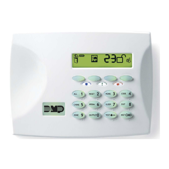
Page 8: Keypad Features
Keypad Features 32-Character Power LED Display 2:52 Armed LED Select Keys Panic Keys RESET HOME Proximity CHIME PERIM SLEEP Credential Reader and Command Key Backlit Logo Back Arrow Key Figure 6: 7000 Series LCD Keypad Power LED POWER ABC SECURITY 32-Character F R I 2 : 52 PM Armed LED... -
Page 9: Enter Characters
Enter Characters Number Pad Choose a character from the table. Use the Greek Characters table if Greek was selected as the keypad language setting. Identify the Number the character correlates with and press that number on the number pad. Identify the Select Key for the character and press that select key on the keypad. Press that select key again for the lowercase letter (Latin characters only). -
Page 10: Panic Key Options
Panic Key Options 2-Button Panic Keys All keypads offer a panic key function that allows users to send panic, emergency, or fire reports to the central station in an emergency. Enable the panic key function in the keypad user menu. Place the supplied icon stickers below the top row select keys. -
Page 11: Program The Panel
PROGRAM THE PANEL Before continuing with programming and setup, you’ll program the keypad in the panel as a device. To access the Programmer menu, reset the panel, enter 6653 (PROG), then press CMD. After completing each of the following steps, press CMD to advance to the next option. Refer to the panel programming guide as needed. -
Page 12: Program The Keypad
PROGRAM THE KEYPAD Refer to the appropriate panel programming guide as needed. Operation for some programming options is restricted to the appropriate model. To access the Keypad Options menu: Hold down the back arrow and CMD keys for two seconds. At SET BRIGHTNESS, enter 3577 (INST) and press CMD. The display changes to KPD OPT KPD DIAG and STOP. - Page 13 If zone 2 does not restore (door closed) within the programmed time, the keypad sounds every other second during the last ten seconds. If zone 2 restores prior to the end of the programmed time, the keypad ends the bypass and indicates the open or short zone condition to the panel.
-
Page 14: Custom Card Format
CUSTOM CARD FORMAT Custom card format programming options are only available on 7063/A, 7073/A, 7163, and 7173 keypads. Card Formats CARD FORMATS Select DMP to allow credentials that use a 26-45 bit data string. The menu advances DMP CUSTOM to REQUIRE SITE. Select CUSTOM to disable DMP format and program slots 1-8 as needed. - Page 15 Site Code Position and Length SITE CODE Enter the site code start position and length in the data string. Press select key 2 to POS: 1 LEN: 8 clear the site code start position and enter a number between 0-255. Press CMD to save.
- Page 16 No Communication with Panel NO COMM WITH PNL Define the relay action when communication with the panel has not occurred for OFF SITE ANY ON 5 seconds: OFF, SITE, ANY, ON, or LAST. Default is OFF. Press any select key or area to change the default relay action: Press the first select key or area to choose OFF (Relay Always Off).
-
Page 17: Additional Programming
Additional Programming Users can manually enter their user code into the keypad which then verifies the user code and its authority with the panel. The 7073/A and 7173 activate the on-board Form C relay releasing a door strike or magnetic lock. To provide added flexibility, the keypad allows connection of an external Wiegand output compatible reader. -
Page 18: Test The Keypad
TEST THE KEYPAD Test the keypad to ensure keypad lighting, individual shortcut keys, and any programmed zones work properly. To begin testing, access the Installer Options menu. Hold down the back arrow and CMD keys at the same time until SET BRIGHTNESS displays. -
Page 19: End User Training
END USER TRAINING This section covers 7063/A, 7073/A, 7163, and 7173 keypads and contains three sections: ▶ Keypad Arming and Disarming ▶ Keypad Access Control ▶ Keypad Entry Delay All of the examples displayed assume that CLOSING CODE is YES in panel programming. Figures 9 through 12 show the user presenting a card to the keypad. -
Page 20: Keypad Access Control
Home/Away System Type Present your card to the reader. If the system is armed, once the card is validated, all areas are disarmed and the keypad displays ALL SYSTEM OFF. If the system is disarmed when you present your card, once the card is validated, HOME SLEEP AWAY displays. -
Page 21: Reference
REFERENCE ULC Commercial Burglary For XR150/XR550 Series panels, keypad zones cannot be used for ULC listed applications. Keypad Bus Wiring Specifications ▶ DMP recommends using 18 or 22-gauge unshielded wire for all keypad and AX-Bus/LX-Bus circuits. Do not use twisted pair or shielded wire for AX-Bus/LX-Bus and Keypad Bus data circuits. All 22-gauge wire must be connected to a power-limited circuit and jacket wrapped. -
Page 22: Readers And Credentials
Readers and Credentials *Delta Proximity Readers and Credentials not evaluated by UL. 125 kHz WIEGAND READERS 125 kHz PROXIMITY CREDENTIALS 13.56 MHz WIEGAND SMARTCARD READERS P-300 Cascade Proximity Reader PSC-1 Standard Light Proximity Card DELTA3* Mullion Mount Smartcard Reader Single-Gang Box Mount Smartcard P-500 Alps Proximity Reader PSK-3... -
Page 23: Specifications
SPECIFICATIONS Keypad Specifications Operating Voltage 12 VDC Dimensions 7” W x 5.25” H x 0.5” D Internal Four Wiegand Internal Door Model Normal/Standby Current Alarm Current Prox Zones Input Strike Relay Reader 7060/A, 7160 72 mA 87 mA 7063/A, 7163 85 mA 100 mA ✔... -
Page 24: Fcc Information
FCC Information This device complies with Part 15 of the FCC Rules. Operation is subject to the following two conditions: This device may not cause harmful interference, and This device must accept any interference received, including interference that may cause undesired operation. Changes or modifications made by the user and not expressly approved by the party responsible for compliance could void the user’s authority to operate the equipment.
Need help?
Do you have a question about the Thinline Series and is the answer not in the manual?
Questions and answers