DMP Electronics 7060 Installation Sheet
Thinline lcd keypads
Hide thumbs
Also See for 7060:
- Installation manual (29 pages) ,
- Quick manual (1 page) ,
- Installation manual (41 pages)
Table of Contents
Advertisement
Quick Links
INST ALLA TION SHEET
7000 Series Thinline LCD Keypads
Models 7060/7063/7070/7073
Description
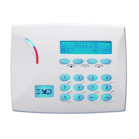
The DMP Model 7060, 7063, 7070, and 7073 Thinline LCD Keypads offer the same flexible features and functionality
as current DMP keypads in a stylish, sleek new design. Each keypad provides four 2-button Panic keys, AC power
LED, Armed LED, 32-character display, backlit logo and keyboard with easy-to-read lettering and an internal speaker.
In addition, the Models 7070 and 7073 keypads also provide four fully programmable Class B, Style A protection zones
you can program for a variety of burglary and access control applications.
The Model 7063 and 7073 keypads provide a built-in proximity card reader designed to read HID 1300 Series and DMP
1400 Series proximity credentials. The Model 7073 keypad also provides a door strike relay and allows Wiegand input
from HID, DMP, or other external card readers.
Installing the Keypad
The keypad housing is designed to easily install on any 4" square box, 3-gang switch box, DMP 695 and 696 backbox,
or a flat surface. Figure 1 shows the keypad housing mounting hole locations.
Removing the Base
The keypad housing is made up of two parts: the front, which contains the circuit board,
keyboard components, and the base. To remove the base, insert a flat screwdriver into one
of the openings on the bottom and twist the screwdriver while pulling the halves apart.
Repeat with the other opening.
Harness Wiring
Figure 1 shows wiring harness assignments. Observe wire colors when connecting the
red, yellow, green, and black wires to the keypad bus. When wiring directly to the panel
terminals, connect red to panel terminal 7, yellow to terminal 8, green to 9, and black to
panel terminal 10. Use 1k Ohm EOL resistors, DMP Model 311, on keypad zones 1 through 4.
The 7060 and 7063 keypads are supplied with a 4-wire harness for panel keypad bus connection.
The 7070 and 7073 keypads are supplied with a 12-wire data bus/zone harness. Four wires connect to the keypad
bus. The remaining eight wires are for the four zone inputs: two wires for each zone.
The 7073 keypad is also supplied with one 5-wire output/reader harness.
Figure 1: Keypad Back Showing Wiring Harness Assignments
Advertisement
Table of Contents

Subscribe to Our Youtube Channel
Related Manuals for DMP Electronics 7060


Summary of Contents for DMP Electronics 7060
-
Page 1: Installing The Keypad
Models 7060/7063/7070/7073 Description The DMP Model 7060, 7063, 7070, and 7073 Thinline LCD Keypads offer the same flexible features and functionality as current DMP keypads in a stylish, sleek new design. Each keypad provides four 2-button Panic keys, AC power LED, Armed LED, 32-character display, backlit logo and keyboard with easy-to-read lettering and an internal speaker. -
Page 2: Additional Power Supply
Wiring Specifications When planning a keypad bus installation, keep in mind the following specifications: 1. DMP recommends using 18 or 22-gauge unshielded wire for all keypad and LX-Bus circuits. Do Not use twisted pair or shielded wire for LX-Bus and keypad bus data circuits. To maintain auxiliary power integrity when using 22-gauge wire do not exceed 500 feet. - Page 3 7073 Door Strike Relay Specifications The 7073 keypad provides one internal Form C single pole, double throw (SPDT) relay for controlling door strikes or magnetic locks. Three wires on the 5-wire harness, Violet (N/C), Gray (Com), and Orange (N/O), allow you to connect devices to the relay.
-
Page 4: Panic Key Options
DMP Model 311, across the White/Brown pair of zone wires on models 7070 and 7073. This allows a Zone Restore message to be sent when the keys are released. Note: The 1k Ohm EOL resistor cannot be installed on 7060 and 7063 keypads. A Zone Restore message is not sent when the keys are released. -
Page 5: End-User Options
End-User Options The 7000 Series Keypads provide three keypad adjustments the end-user can make through a User Options Menu. The user can also view the keypad model number and address in User Options. On all keypads press and hold the Back Arrow (<—) and COMMAND (CMD) keys for two seconds to access User Options. The keypad display changes to SET BRIGHTNESS. -
Page 6: Installer Options Menu
Installer Options Menu The 7000 Series keypads also contain Keypad Option and Keypad Diagnostic programs that allow installers and service technicians to configure and test keypad operation. Access the Installer Menu Access the Installer Options Menu through the User Options function. Hold down the <— and CMD keys for two seconds to display the SET BRIGHTNESS option. - Page 7 Z3 OPEN Z4 OPEN protection zones. The status is shown as OPEN, SHRT, or OKAY. Note: The Zone Test displays on 7060 and 7063 keypads, but is not operational. Input Wiegand (7063 and 7073 only) INPUT WIEGAND This option tests the internal and external reader input from proximity credentials.
-
Page 8: Keypad Arming And Disarming
Additional Programming for 7063 and 7073 Thinline Keypads The 7063 and 7073 keypads allow users to present a proximity credential to the built-in proximity reader located in the keypad backlit logo area. Users can also manually enter their user code into the keypad. The keypad verifies the user code and its authority with the panel. -
Page 9: Keypad Door Strike
All/Perimeter System Arming and Disarming Press CMD, the keypad displays PERIM ALL (when arming) or DISARM?. Press the Select key under the desired option. The keypad displays ENTER CODE: -. Present your card to the reader. Once validated by the system, the selected areas arm or disarm automatically. -
Page 10: Keypad Specifications
NORM/STANDBY ALARM INTERNAL WIEGAND INTERNAL FORM C MODEL 4-ZONES CURRENT CURRENT PROX READER INPUT DOOR STRIKE RELAY 7060 72mA 87mA 7063 85mA 100mA 72mA + 1.6mA 87mA + 2mA 7070 per active zone per active zone 85mA + 1.6mA 100mA + 2mA...
Need help?
Do you have a question about the 7060 and is the answer not in the manual?
Questions and answers