DMP Electronics 7800 Series Installation And Programming Manual
Graphic touchscreen keypad
Hide thumbs
Also See for 7800 Series:
- Installation and programming manual (52 pages) ,
- Quick start manual (2 pages) ,
- Installation and programming manual (26 pages)
Table of Contents
Advertisement
Advertisement
Table of Contents

Subscribe to Our Youtube Channel
Related Manuals for DMP Electronics 7800 Series


Summary of Contents for DMP Electronics 7800 Series
- Page 1 7800 Series Graphic Touchscreen Keypad INSTALLATION AND PROGRAMMING GUIDE...
-
Page 3: Table Of Contents
TABLE OF CONTENTS About the Keypad ........1 Program the Panel ........15 7872 ..................1 Device Setup ..............15 7873 ..................1 Device Number ..............15 7873H ................... 1 Device Name ...............15 Device Type .................16 Keypad Features .........2 Communication Type ............16 Programmable Carousel Menu ......... - Page 4 Keypad Bus Wiring Specifications ..45 System Type ..............30 Dealer Logo ............... 30 Public Card Formats ....... 46 Dealer Info ................. 30 Carousel Z-Wave Items ...........31 Readers and Credentials ......47 Shortcut Items ..............31 Select Language ...............32 Ordering Information ......49 Keypads ................49 Additional Programming ......33 Accessories..............
-
Page 5: About The Keypad
ABOUT THE KEYPAD 7800 Series Graphic Touchscreen Keypads offer flexible features and functionality. Each keypad provides optional panic keys, an AC Power/Armed LED, an internal speaker, a simple terminal connection to a 4-wire keypad bus, and optional backboxes for conduit or wall-mount applications. -
Page 6: Keypad Features
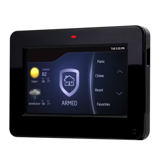
Proximity Reader Dealer Logo Carousel Menu microSD Card Slot Interactive Arming/ Disarming Shield Press the Navigation Arrows or touch and drag the menu to scroll Local Weather Figure 1: Keypad Features 7800 Series Installation and Programming Guide Digital Monitoring Products, Inc. -
Page 7: Programmable Carousel Menu
The Arm/Disarm LED remains lit. A Brightness setting of 0 allows both the keypad display and LED to turn off automatically after a period of inactivity. To wake the display, tap any part of the touchscreen surface. Figure 2: Keypad Options Digital Monitoring Products, Inc. 7800 Series Installation and Programming Guide... -
Page 8: Enter Characters
Press abc to enter lowercase letters. • • Press !@# to enter special characters. Press 123 to enter numbers and to return to the number pad. See Figure 4. • 7800 Series Installation and Programming Guide Digital Monitoring Products, Inc. - Page 9 Return to Home Screen Select Areas Special Characters Uppercase/ Lowercase Letters Number Pad Figure 3: Number Pad Figure 4: Standard Keyboard Digital Monitoring Products, Inc. 7800 Series Installation and Programming Guide...
-
Page 10: Install The Keypad
Repeat with the other slot. Separate the cover from the base and set the Base cover containing the keypad components aside. See Figure 5. Figure 5: Separate the Keypad Housing 7800 Series Installation and Programming Guide Digital Monitoring Products, Inc. -
Page 11: Wire The Keypad
• Zone 1: Brown White/White Brown • Zone 2: Red White/White Red (Zone 2 Bypass) • Zone 3: Orange White/White Orange (REX) • Zone 4: Yellow White/White Yellow Digital Monitoring Products, Inc. 7800 Series Installation and Programming Guide... - Page 12 White – Connect Reader Data 1 1K EOL Red – Keypad Power Green/White – Connect Reader Data 0 Black Black – Ground Green Yellow Red – Keypad Power Figure 6: Mounting Holes and Wiring 7800 Series Installation and Programming Guide Digital Monitoring Products, Inc.
-
Page 13: Wire For Access Control
Connect the Data 1 (reader) wire to the white wire on the 5-wire keypad cable. Connect the Data 0 (reader) wire to the green/white wire on the 5–wire keypad cable. See Figure 7. Digital Monitoring Products, Inc. 7800 Series Installation and Programming Guide... - Page 14 Zone 1 (7/0 Panic) Black – Ground Green – Receive Data Yellow – Send Data Red – Keypad Power External Card Reader To Panel Keypad Bus Figure 7: Access Control Wiring 7800 Series Installation and Programming Guide Digital Monitoring Products, Inc.
-
Page 15: Wire The Electronic Lock
NO and C wires. Conversely, if the device is connected to the NC and C wires, install the 333 Suppressor on NC and C wires. See Figure 8 and Figure 9. Digital Monitoring Products, Inc. 7800 Series Installation and Programming Guide... - Page 16 Green/White – D0 White – D1 Orange – N/O Gray – C Violet – N/C Model 333 Supressor Keypad 5-Wire Harness – Power Supply Door Strike Relay Figure 9: Typical Door Strike Wiring 7800 Series Installation and Programming Guide Digital Monitoring Products, Inc.
-
Page 17: Mount The Keypad
See Figure 10. Use #6 screws to secure the keypad base to the surface. Place the keypad cover back onto the base and snap into place. Digital Monitoring Products, Inc. 7800 Series Installation and Programming Guide... - Page 18 Figure 10: Mounting Hole Locations 7800 Series Installation and Programming Guide Digital Monitoring Products, Inc.
-
Page 19: Program The Panel
Set the keypad address from 1-8 for XT30, XT50, and XR150 DEVICE NO: - Series panels, or 1-16 for XR550 Series panels. Device Name DEVICE SETUP Enter the a name for the device. *UNUSED* Digital Monitoring Products, Inc. 7800 Series Installation and Programming Guide... -
Page 20: Device Type
Ensure the COMM TYPE is set to KPD (Keypad Bus). COMM TYPE: Configure additional options as needed. To configure custom card options for the keypad, do not program CARD OPTIONS in Device Setup. 7800 Series Installation and Programming Guide Digital Monitoring Products, Inc. -
Page 21: Program The Keypad
01. To change the current address, press any select area to clear the keypad display, enter the new address, and press CMD. It’s not necessary to enter a leading zero for addresses 1 to 9. Digital Monitoring Products, Inc. 7800 Series Installation and Programming Guide... -
Page 22: Keypad Mode
Use this option to enable or disable the panic keys. Press the icon name: PN (panic), EM (emergency), and FI (fire). Once the panic option is enabled, an asterisk displays next to the selected options. 7800 Series Installation and Programming Guide Digital Monitoring Products, Inc. -
Page 23: Activate Zone 2 Bypass
If the zone does not restore before the programmed time, the keypad ends the bypass and indicates the open or short zone condition to the panel. Digital Monitoring Products, Inc. 7800 Series Installation and Programming Guide... - Page 24 Select NO (default) to leave the relay on when Zone 2 changes NO YES CHANGE? to an open or short condition during bypass. Select YES to turn the relay off when Zone 2 changes to open or short during bypass. 7800 Series Installation and Programming Guide Digital Monitoring Products, Inc.
-
Page 25: Activate Zone 3 Request To Exit
Activate Bypass Only Wire zone 3 as normally closed with an in-line 1K Ohm resistor. When zone 3 opens from a normal state, only a bypass occurs: the onboard relay does not activate. Digital Monitoring Products, Inc. 7800 Series Installation and Programming Guide... -
Page 26: Arming/Disarming Wait Time
205 or higher, presenting a credential to the keypad automatically initiates the arming sequence after the arming wait time expires. All/Perimeter systems arm All. Home/Sleep/ Away and Home/Away systems arm Away. 7800 Series Installation and Programming Guide Digital Monitoring Products, Inc. -
Page 27: Card Options
ZN 3 REX TIME. No user code information is sent to the panel. The menu advances to NO COMM WITH PNL. The default card format is DMP. Digital Monitoring Products, Inc. 7800 Series Installation and Programming Guide... - Page 28 SINGLE CARD FORMAT and WIEGAND CODE LENGTH will default to 45. Format Name FORMAT NAME Press any select area to rename the card format. Press CMD to *UNUSED* save and advance. 7800 Series Installation and Programming Guide Digital Monitoring Products, Inc.
- Page 29 Position = 1 Position = 9 Received Position = 0 Length = 8 Length = 16 Position = 25 Example: Wiegand Code Length = 26 bits Figure 12: Wiegand Data Stream Bit Location Digital Monitoring Products, Inc. 7800 Series Installation and Programming Guide...
- Page 30 0-255. Press CMD to save. Default is 9. Press select area 4 to clear the user code length and enter a number between 16-64. Press CMD to save. The default is the DMP value of 16. 7800 Series Installation and Programming Guide Digital Monitoring Products, Inc.
-
Page 31: Require Site Code
In the keypad display, enter site code 1 and press CMD. The display will ask for site code 2 followed by site code 3 and so on. When you have selected the site code you want to change, press CMD. Digital Monitoring Products, Inc. 7800 Series Installation and Programming Guide... -
Page 32: Number Of User Code Digits
Define the relay action when communication with the panel has not occurred for 5 seconds: OFF, SITE, ANY, ON, or LAST. Default is OFF. Press any select key or area to change the default relay action: 7800 Series Installation and Programming Guide Digital Monitoring Products, Inc. - Page 33 Press CMD to display additional actions. Press the first LAST select key or area to choose LAST (Keep Last State). The relay remains in the same state and does not change when communication is lost. Digital Monitoring Products, Inc. 7800 Series Installation and Programming Guide...
-
Page 34: System Type
Adding Info Sure? While the info is being uploaded to the ADDING INFO keypad, the keypad displays ADDING INFO. ADDING INFO SURE? COMPLETED displays to confirm a successful upload. Press and release the microSD card to eject. 7800 Series Installation and Programming Guide Digital Monitoring Products, Inc. -
Page 35: Carousel Z-Wave Items
Press CMD at the bottom of the screen to advance to the next options screen and the back arrow return to the previous screen. Default is no items selected. See Figure 14: Carousel Z-Wave Figure 14. Items Digital Monitoring Products, Inc. 7800 Series Installation and Programming Guide... -
Page 36: Shortcut Items
Default is English. Note: The keypad does not translate information from the panel that displays on Figure 16: Select Language the keypad screen. See Figure 16. 7800 Series Installation and Programming Guide Digital Monitoring Products, Inc. -
Page 37: Additional Programming
Press any select key. Choose ADD. At ENTER CODE, present the credential to the reader. The keypad works by reading the user code from the data string sent by the access control reader. Digital Monitoring Products, Inc. 7800 Series Installation and Programming Guide... -
Page 38: Update The Keypad
Press CMD until Restart Keypad displays. Press Restart. Do not remove the microSD card or disrupt power. 10. When the keypad is finished restarting and returns to the home screen, remove the microSD card. 7800 Series Installation and Programming Guide Digital Monitoring Products, Inc. -
Page 39: Test The Keypad
Test the Credential Reader INPUT WIEGAND This option tests the internal and external reader input from proximity credentials. The display shows OKAY each time a good proximity read is received. Digital Monitoring Products, Inc. 7800 Series Installation and Programming Guide... -
Page 40: End User Training
Tap CMD to advance to MENU? NO YES. Tap YES. Enter your user code, then tap CMD. Tap CMD to advance through the menu items. To enter a menu, tap any select area. 7800 Series Installation and Programming Guide Digital Monitoring Products, Inc. -
Page 41: Arm And Disarm The System
If a selection is not made, all areas will automatically arm AWAY. If ENTER CODE: displays, enter a user code at the keypad or present a credential to the proximity reader. Digital Monitoring Products, Inc. 7800 Series Installation and Programming Guide... -
Page 42: Use Access Control
The relay activates for 5 seconds. During this shield, present your access card. time, you can open the door. You have 40 seconds to exit and close the door before the time expires. Figure 18: Present Access Card 7800 Series Installation and Programming Guide Digital Monitoring Products, Inc. - Page 43 Door Strike Relay. Area systems provide a delay to allow selected areas only to be disarmed. See Figure 19. Entry delay starts. Present an authorized card and the system disarms. Figure 19: Entry Delay Digital Monitoring Products, Inc. 7800 Series Installation and Programming Guide...
-
Page 44: Icon Reference
Ready To Exit Exit Timer Popups Menu Enter Code Arm Instant Attention List Alert Home Installer Navigation Edit Arming Options Panic Options Home Sleep Away All System Emergency Perimeter Police Fire 7800 Series Installation and Programming Guide Digital Monitoring Products, Inc. - Page 45 Z-Wave Thermostats Controls Decrease Increase Auto Heat Cool Room Temp Status Bar Header System Ready Attention List Armed (Area) Home Sleep Away Perimeter All System Chime Battery Trouble AC Trouble Wi-Fi Digital Monitoring Products, Inc. 7800 Series Installation and Programming Guide...
-
Page 46: Change System Wi-Fi Password
Use the onscreen keyboard to enter your password: • Press ABC to enter uppercase letters • Press abc to enter lowercase letters • Press !@# to enter special characters • Press 123 to enter numbers Tap CMD. 7800 Series Installation and Programming Guide Digital Monitoring Products, Inc. - Page 47 Figure 20: Incorrect Wi-Fi Password Dialog Figure 21: Enter Wi-Fi Password Screen Digital Monitoring Products, Inc. 7800 Series Installation and Programming Guide...
-
Page 48: Clean The Keypad
Wait 10 seconds, then completely dry all keypad surfaces. If necessary, use a clean, dry microfiber cloth to gently remove streaking. 7800 Series Installation and Programming Guide Digital Monitoring Products, Inc. -
Page 49: Keypad Bus Wiring Specifications
When voltage is too low, the devices cannot operate properly. For additional information refer to the panel’s Installation Guide or the 710 Installation Sheet (LT-0310). Digital Monitoring Products, Inc. 7800 Series Installation and Programming Guide... -
Page 50: Public Card Formats
CARD FORMAT CODE POSITION LENGTH POSITION LENGTH DIGITS LENGTH H10301 26 BIT H10302 37 BIT W/O H10304 37 BIT W/FAC FARPOINTE 39 BIT CORPORATE 1000 35 BIT CORPORATE 1000 48 BIT 7800 Series Installation and Programming Guide Digital Monitoring Products, Inc. -
Page 51: Readers And Credentials
MaxiProx® Proximity Reader 1351 ProxPass® PP-6005B ProxPoint® Plus Proximity Reader ProxPro Proximity Reader With 1386 IsoProx II® Card PR-5355 Keypad PR-5455 ProxPro® II Proximity Reader TL-5395 ThinLine II® Proximity Reader Digital Monitoring Products, Inc. 7800 Series Installation and Programming Guide... - Page 52 Single-Gang Box Mount Smartcard CSK-2 MIFARE® DESfire® EV2 Key Fob DELTA5* Reader Smartcard DELTA6.4* Smartcard Reader With Keypad CSR-35P Bluetooth Smartcard Reader *Delta Proximity Readers and Credentials not evaluated by UL. 7800 Series Installation and Programming Guide Digital Monitoring Products, Inc.
-
Page 53: Ordering Information
Graphic Touchscreen Keypad (black, 4 zones, prox reader, relay) 7873-W Graphic Touchscreen Keypad (white, 4 zones, prox reader, relay) 7873H-W High Security Graphic Touchscreen Keypad (white, 4 zones, prox reader, relay) Digital Monitoring Products, Inc. 7800 Series Installation and Programming Guide... -
Page 54: Accessories
In Wall Mount Backbox (white) 695-7800-SFC-W 7800 Keypad Conduit Backbox (white) 698-7800-B Plastic Keypad Wall Cover (black) 698-7800-W Plastic Keypad Wall Cover (white) 699-7800 Keypad Deskstand (with hardware and cord) 7800 Series Installation and Programming Guide Digital Monitoring Products, Inc. -
Page 55: Compliance Specifications
Do not mount keypad on metal surfaces or metallic electrical boxes. • For listed access control applications, the keypad must be installed within the protected area and all REX devices must be Listed to UL 294. Digital Monitoring Products, Inc. 7800 Series Installation and Programming Guide... -
Page 56: Certifications
ANSI/UL 294 Access Control System Units ANSI/UL 365 Police Connected Burglar ANSI/UL 609 Local Burglar ANSI/UL 1023 Household Burglar ANSI/UL 1076 Proprietary Burglar ANSI/UL 1610 Central Station Burglar ANSI/UL 985 Household Fire Warning 7800 Series Installation and Programming Guide Digital Monitoring Products, Inc. -
Page 57: Fcc Information
• Connect the equipment into an outlet on a circuit different from that to which the receiver is connected. • Consult the dealer or an experienced radio/TV technician for help. Digital Monitoring Products, Inc. 7800 Series Installation and Programming Guide... -
Page 58: Industry Canada Information
Information furnished is believed to be accurate and reliable. This information is subject to change without notice. 7800 Series Installation and Programming Guide Digital Monitoring Products, Inc. - Page 60 LT-1162 20291 1.03 © 2020 Digital Monitoring Products, Inc.
Need help?
Do you have a question about the 7800 Series and is the answer not in the manual?
Questions and answers