Lenze i550 Series Project Planning Manual
Cabinet 0.25...132 kw
Hide thumbs
Also See for i550 Series:
- Commissioning manual (704 pages) ,
- Mounting and switch-on instructions (212 pages) ,
- Project planning manual (141 pages)
Table of Contents
Advertisement
Quick Links
Advertisement
Table of Contents

Subscribe to Our Youtube Channel
Related Manuals for Lenze i550 Series


Summary of Contents for Lenze i550 Series
- Page 1 Project planning EN Inverters Inverter i550 Cabinet 0.25 ... 132 kW...
-
Page 3: Table Of Contents
Contents Contents About this document Document description Further documents Notations and conventions Product information Product description Identification of the products Features The modular system The concept Topologies / network Ways of commissioning Functions Overview Motor control types Features Motor setting range Information on project planning Project planning process Dimensioning... - Page 4 Contents Information on electrical installation Important notes Preparation Mains connection 1-phase mains connection 120 V 1-phase mains connection 230/240 V 3-phase mains connection 230/240 V 3-phase mains connection 400 V 3-phase mains connection 400 V "Light Duty" 3-phase mains connection 480 V 3-phase mains connection 480 V "Light Duty"...
- Page 5 Contents Technical data Standards and operating conditions Conformities/approvals Protection of persons and device protection EMC data Motor connection Environmental conditions Electrical supply conditions Certification of the integrated safety 1-phase mains connection 120 V Rated data Fusing data Terminal data Brake resistors Mains chokes 1-phase mains connection 230/240 V Rated data...
- Page 6 Contents 3-phase mains connection 480 V Rated data Fusing data Terminal data Brake resistors Mains chokes RFI filters / Mains filters 3-phase mains connection 480 V "Light Duty" Rated data Fusing data Terminal data Brake resistors Mains chokes RFI filters / Mains filters Dimensions Product extensions Overview...
- Page 7 Contents Accessories Overview Operation and diagnostics Keypad External keypad USB module WLAN module Blanking cover Setpoint potentiometer Memory modules Memory module copier Brake resistors Mains chokes RFI filters / Mains filters Sine filter Power supply units Brake switches Mounting Shield mounting kit Terminal strips Purchase order Notes on ordering...
-
Page 8: About This Document
Exports in different formats EPLAN macros Project planning, documentation and management of projects for P8. • Data reference via Lenze or EPLAN data portal Information and tools with regard to the Lenze products can be found on the Internet: http://www.lenze.com à Download... -
Page 9: Notations And Conventions
About this document Notations and conventions Notations and conventions This document uses the following conventions to distinguish different types of information: Numeric notation Decimal separator Point The decimal point is always used. Example: 1 234.56 Warning UL warning Are used in English and French. UR warning Text Engineering tools... -
Page 10: Product Information
Product information Product information Product description i500 is the new inverter series - a streamlined design, scalable functionality and exceptional user-friendliness. The functional safety describes the necessary measures that need to be taken by means of electrical or electronic equipment to prevent or eliminate dangers due to functional errors. Protective devices prevent any human access to dangerous areas during normal operation. - Page 11 Product information Product description Application ranges Pumps and fans • Conveying and travelling drives • Forming, tool and hoist drives •...
-
Page 12: Identification Of The Products
Product information Identification of the products Identification of the products When the technical data of the different versions was listed, the product name was entered because it is easier to read than the individual product code of the product. The product name is also used for categorising the accessories. - Page 13 Product information Identification of the products Inverter series Type Rated power Rated mains voltage Number of Inverter phases 0.25 i550-C0.25/120-1 0.37 i550-C0.37/120-1 Inverter i550 Cabinet 0.75 i550-C0.75/120-1 i550-C1.1/120-1 Inverter series Type Rated power Rated mains voltage Number of Inverter phases i550-C0.25/230-1 0.25 i550-C0.25/230-2...
- Page 14 Product information Identification of the products Inverter series Type Rated power Rated mains voltage Number of Inverter phases Light duty Heavy Duty 0.37 i550-C0.37/400-3 0.55 i550-C0.55/400-3 0.75 i550-C0.75/400-3 i550-C1.1/400-3 i550-C1.5/400-3 i550-C2.2/400-3 i550-C3.0/400-3 i550-C4.0/400-3 i550-C5.5/400-3 i550-C7.5/400-3 Inverter i550 i550-C11/400-3 Cabinet 18.5 i550-C15/400-3 18.5 i550-C18/400-3...
-
Page 15: Features
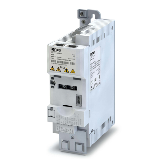
Product information Features Features The following figures give an overview of the elements and connections on the devices. Posi- tion, size and appearance of elements and connections may vary depending on the capacity and size of the equipment. Some equipment may be optional. Example of 0.25 kW ... - Page 16 Product information Features Example of 3 kW ... 11 kW PE connec on Mains connec on X100 DC-bus X100 connec on Relay output X9 Network X2xx Op on Network shield connec on Network status LEDs Op on Basic network se ngs DIP switch or rotary encoder switch Interface X16 Diagnos c module...
- Page 17 Product information Features Example of 15 kW ... 45 kW PE connec on Mains connec on X100 Anschluss -Bus X100 IT screw Network X2xx Relay output X9 Op on Network shield connec on Network status LEDs Op on Basic network se ngs DIP switch or rotary encoder switch Interface X16 Diagnos c module...
- Page 18 Product information Features Example of 55 kW ... 75 kW...
- Page 19 Product information Features Example of 90 kW ... 110 kW Position and meaning of the nameplates Complete inverter Inverter consisting of components ② ② ① ④ ① ① ③ Technical data of the inverter Technical data of the component ① ①...
-
Page 20: The Modular System
Product information The modular system The concept The modular system The concept Thanks to its flexible concept and modular structure consisting of power unit, control unit and safety module, the inverter can be optimally adapted to the application. This provides the user with a flexible logistics concept - ordered as a complete inverter or sin- gle components. -
Page 21: Topologies / Network
CANopen® is a registered community trademark of the CAN user organisation CiA® (CAN in Automation e. V.). Device descriptions for the download: EDS files for Lenze devices The Modbus protocol is an open communication protocol based on a client/server architecture and developed for the communication with programmable logic controllers. -
Page 22: Ways Of Commissioning
Smart-Keypad-App for Android or iOS • Ideal for the parameterisation of simple applications such as a conveyor belt. The Lenze Smart Keypad app can be found in the Google Play Store or in the Apple App Store. Android »EASY Starter«... -
Page 23: Functions
Product information Functions Overview Functions Overview With regard to their functionality, the inverters i550 are adapted to extensive applications. This is also reflected in the total scope of the products. Functions Motor control Monitoring V/f characteristic control linear/square-law (VFC plus) Short circuit V/f characteristic control (VFC closed loop) earth fault... -
Page 24: Motor Control Types
VFCplus SLVC SC ASM Three-phase AC motors ● ● ● ● ● ● ● ● ● m500 ● ● ● Lenze synchronous servo motors are not suitable for the use with inverters, e. g. the MCS, MCM or m850 types. -
Page 25: Features
Features Motor setting range Rated point 120 Hz Only possible with Lenze MF motors. The rated motor torque is available up to 120 Hz. Compared to the 50-Hz operation, the setting range increases by 2.5 times. Thus, a smaller motor can be selected at the same rated power. - Page 26 Product information Features Motor setting range V/f at 87 Hz M, U Voltage Mains voltage Torque Rated torque rated Frequency Rated frequency rated Rated point 50 Hz The rated motor torque is available up to 50 Hz. V/f at 50 Hz M, U Voltage Mains voltage...
-
Page 27: Information On Project Planning
Detailed: In order to optimise the selection of the inverter and all drive components, it is worth to execute the detailed system dimensioning based on the physical requirements of the application. For this purpose, Lenze provides the «Drive Solution Designer» (DSD) design pro- gram. - Page 28 Information on project planning Project planning process Dimensioning Calculate range of adjustment and determine rated point Calculation Setting range L,max L,min Setting range Rated point 50 Hz ≤ 2.50 (20 - 50 Hz) 87 Hz Motor with integral fan ≤ 4.35 (20 - 87Hz) 120 Hz ≤...
- Page 29 Information on project planning Project planning process Dimensioning Determine the inverter based on the rated data for the "Light Duty" load characteristic Check Output current Continuous operation ≥ I / (k N,Mot H,INV TU,INV Overcurrent operation cycle 15 s ≥ I x 1.65 / (k N,Mot H,INV...
-
Page 30: Operation In Motor And Generator Mode
Information on project planning Project planning process Operation in motor and generator mode Final configuration Product extensions and accessories can be found here: Product extensions • ^ 212 Accessories • ^ 238 Operation in motor and generator mode The energy analysis differs between operation in motor mode and generator mode. During operation in motor mode, the energy flows from the supplying mains via the inverter to the motor which converts electrical energy into mechanical energy (e. -
Page 31: Overcurrent Operation
Information on project planning Project planning process Overcurrent operation Overcurrent operation The inverters can be driven at higher amperages beyond the rated current if the duration of this overcurrent operation is time limited. Two utilisation cycles of 15 s and 180 s are defined. Within these utilisation cycles, an overcur- rent is possible for a certain time if afterwards an accordingly long recovery phase takes place. - Page 32 Information on project planning Project planning process Overcurrent operation Inverter load characteristics The inverter has two different load characteristics: "Light Duty" and "Heavy Duty". The "Light Duty" load characteristic allows for a higher output current with restrictions regarding over- load capacity, ambient temperature and switching frequency. This allows the motor required for the application to be driven by a less powerful inverter.
-
Page 33: Safety Instructions
The procedural notes and circuit details described in this document are only proposals. It is up to the user to check whether they can be adapted to the particular applications. Lenze does not take any responsibility for the suitability of the procedures and circuit proposals descri-... -
Page 34: Application As Directed
The product must only be actuated with motors that are suitable for the operation with • inverters. Lenze L-force motors meet the requirements Exception: m240 motors are designed for mains operation only. The user is not allowed to change inverters that come with integrated safety technology. -
Page 35: Handling
Information on project planning Safety instructions Handling Handling Transport, storage Observe the notes regarding transport, storage and correct handling. Ensure proper handling and avoid mechanical stress. Do not bend any components and do not change any insulation distances during transport or handling. Do not touch any electronic components and contacts. Inverters contain electrostatically sensitive components which can easily be damaged by inap- propriate handling. - Page 36 Information on project planning Safety instructions Handling Disposal In accordance with the current provisions, inverters and accessories have to be disposed of by means of professional recycling. Inverters contain recyclable raw material such as metal, plas- tics an electronic components.
-
Page 37: Residual Hazards
Information on project planning Safety instructions Residual hazards Residual hazards Even if notes given are taken into consideration and protective measures are implemented, the occurrence of residual risks cannot be fully prevented. The user must take the residual hazards mentioned into consideration in the risk assessment for his/her machine/system. - Page 38 Information on project planning Safety instructions Residual hazards Risks when exchanging devices WARNING! Incorrect handling of devices. Device damage. ▶ Check the compatibility of the devices before exchanging. ▶ Check the memory cards of the devices before exchanging. ▶ Set the safety address. ▶...
-
Page 39: Control Cabinet Structure
Information on project planning Control cabinet structure Arrangement of components Control cabinet structure Control cabinet requirements Protection against electromagnetic interferences • Compliance with the ambient conditions of the installed components • Mounting plate requirements The mounting plate must be electrically conductive. •... -
Page 40: Cables
Information on project planning Control cabinet structure Earthing concept Cables Requirements The cables used must correspond to the requirements at the location (e. g. EN 60204−1, • UL). The cable cross-section must be dimensioned for the assigned fusing. Observe national •... -
Page 41: Emc-Compliant Installation
Information on project planning Control cabinet structure EMC-compliant installation EMC-compliant installation Structure of a CE-typical drive system The drive system (frequency inverter and drive) corresponds to 2014/30/EU: EMC Directive if it is installed according to the specifications of the CE-typical drive system. The structure in the control cabinet must support the EMC-compliant installation with shiel- ded cables. - Page 42 • separately from the motor cable. In Lenze system cables, the cable for brake control is integrated into the motor cable. If this cable is not required for brake control, it can also be used to connect the motor temperature monitoring up to a length of 50 m.
- Page 43 Information on project planning Control cabinet structure EMC-compliant installation Detecting and eliminating EMC interferences Trouble Cause Remedy Interferences of analog setpoints of your own Unshielded motor cable has been used Use shielded motor cable or other devices and measuring systems Shield contact is not extensive enough Carry out optimal shielding as specified Shield of the motor cable is interrupted, e.
-
Page 44: Information On Mechanical Installation
Information on mechanical installation Important notes Information on mechanical installation Important notes After being mounted ,the safety module cannot be removed anymore! Measures for cooling during operation Ensure unimpeded ventilation of cooling air and outlet of exhaust air. • If the cooling air is polluted (fluff, (conductive) dust, soot, aggressive gases), take adequate •... -
Page 45: Preparation
Information on mechanical installation Preparation Preparation Further data and information for mechanical mounting: 4Control cabinet structure ^ 39 4Dimensions ^ 201 The scope of supply of the inverter comprises mounting instructions. They describe technical data and information on mechanical and electrical installa- tion. -
Page 46: Information On Electrical Installation
Information on electrical installation Information on electrical installation Important notes DANGER! Electrical voltage Possible consequences: Death or severe injuries ▶ Any work on the inverter must only be carried out in the deenergised state. ▶ Inverter up to 45 kW: After switching off the mains voltage, wait for at least 180 s before you start working. - Page 47 Possible consequences: The filters may be destroyed when an earth fault occurs. Possible consequences: Monitoring of the IT system may be triggered. ▶ Do not use mains filters and RFI filters from Lenze in IT systems. ▶ Before using the inverter in the IT system, remove the IT screws.
-
Page 48: Preparation
Information on electrical installation Preparation When implementing machines and systems for the use in the UL/CSA scope, you have to observe the relevant special notes. These notes are marked with "UL marking". WARNING! ▶ UL marking ▶ Suitable for motor group installation. ▶... -
Page 49: Mains Connection
Information on electrical installation Mains connection Mains connection The following should be considered for the mains connection of inverters: Single inverters are either directly connected to the AC system or via upstream filters. RFI fil- ters are already integrated in many inverters. Depending on the requirements, mains chokes or mains filters can be used. -
Page 50: 1-Phase Mains Connection 120 V
Information on electrical installation Mains connection 1-phase mains connection 120 V 1-phase mains connection 120 V The connection plan is valid for the inverters i550-Cxxx/120-1. Inverters i550-Cxxx/120-1 do not have an integrated RFI filter in the AC mains supply. In order to meet the EMC requirements according to EN 61800−3, an external EMC filter according to IEC EN 60939 must be used. -
Page 51: 1-Phase Mains Connection 230/240 V
Information on electrical installation Mains connection 1-phase mains connection 230/240 V 1-phase mains connection 230/240 V The connection plan is valid for the inverters i550-Cxxx/230-1. 3/N/ PE 3/N/ PE 2/N/ PE 400 V 208 V ... 240 V 208 V ... 240 V …... - Page 52 Information on electrical installation Mains connection 1-phase mains connection 230/240 V The connection plan is valid for the inverters i550-Cxxx/230-2. Inverters i550-Cxxx/230-2 do not have an integrated RFI filter in the AC mains supply. In order to meet the EMC requirements according to EN 61800−3, an external EMC filter according to IEC EN 60939 must be used.
-
Page 53: 3-Phase Mains Connection 230/240 V
Information on electrical installation Mains connection 3-phase mains connection 230/240 V 3-phase mains connection 230/240 V The connection plan is valid for the inverters i550-Cxxx/230-3. Inverters i550-Cxxx/230-3 do not have an integrated RFI filter in the AC mains supply. In order to meet the EMC requirements according to EN 61800−3, an external EMC filter according to IEC EN 60939 must be used. - Page 54 Information on electrical installation Mains connection 3-phase mains connection 230/240 V The connection plan is valid for the inverters i550-Cxxx/230-2. Inverters i550-Cxxx/230-2 do not have an integrated RFI filter in the AC mains supply. In order to meet the EMC requirements according to EN 61800−3, an external EMC filter according to IEC EN 60939 must be used.
-
Page 55: 3-Phase Mains Connection 400 V
Information on electrical installation Mains connection 3-phase mains connection 400 V "Light Duty" 3-phase mains connection 400 V The connection plan is valid for the inverters i550-Cxxx/400-3. 3/N/ PE AC 400 V … 3/ PE 340 V ... 528 V 45 Hz ... -
Page 56: 3-Phase Mains Connection 480 V
Information on electrical installation Mains connection 3-phase mains connection 480 V "Light Duty" 3-phase mains connection 480 V The connection plan is valid for the inverters i550-Cxxx/400-3. 3/N/ PE AC 480 V … 3/ PE 340 V ... 528 V 45 Hz ... -
Page 57: Motor Connection
Information on electrical installation Motor connection Motor connection Switching in the motor cable Switching on the motor side of the inverter is permissible: For safety shutdown (emergency stop). In case several motors are driven by one inverter (only in V/f operating mode). Please note the following: The switching elements on the motor side must be dimensioned for with the maximum occurring load. -
Page 58: Connection To The It System
Information on electrical installation Connection to the IT system Connection to the IT system I55AE125x, I55AE137x, I55AE175x, I55AE211x TX10 TX10 I55AE230F, I55AE240F, I55AE255F, I55AE275F, I55AE311F I55AE240D, I55AE255D TX10 TX10 TX10... - Page 59 Information on electrical installation Connection to the IT system I55AE315F, I55AE318F, I55AE322F, I55AE330F, I55AE337F, I55AE345F...
-
Page 60: Connection Of Motor Temperature Monitoring
Information on electrical installation Connection of motor temperature monitoring I55AE355F, I55AE375F, I55AE390F, I55AE411F Connection of motor temperature monitoring If the terminal X109 is used, e. g. to connect an external PTC thermistor (PTC) or a thermal contact, ensure at least one basic insulation to the potentials of motor, mains and control terminals to not restrict the protective separation of the control terminals. -
Page 61: Brake Resistor Connection
Information on electrical installation Brake resistor connection Brake resistor connection If wiring of the brake resistor can be kept short, it is sufficient to twist the cables. Up to 0.5 m of cable length, this applies to the cable of the brake resistor and the cable of temperature monitoring. -
Page 62: Dc-Bus Connection
Information on electrical installation Control connections DC-bus connection Rated mains voltage DC voltage range DC 450 V - 0 % ... 750 V + 0 % Control connections Terminal description Control terminals Connection Connection type pluggable spring terminal Max. cable cross-section mm²... -
Page 63: Networks
Information on electrical installation Networks EtherCAT Networks CANopen Typical topologies Line X216 X216 X216 X216 Terminal description CANopen Connection X216 Connection type pluggable double spring terminal Max. cable cross-section mm² Max. cable cross-section Stripping length Stripping length inch 0.39 Tightening torque Tightening torque lb-in Required tool... -
Page 64: Ethernet/Ip
Information on electrical installation Networks Modbus RTU EtherNet/IP Typical topologies Line Tree Ring Scanner Switch Adapter Bus-related information Name EtherNet/IP Communication medium Ethernet 10 Mbps, 100 Mbps, half duplex, full duplex Used for... Connection of the inverter to an Ether- Net/IP network Connection system RJ45... -
Page 65: Modbus Tcp
Information on electrical installation Networks POWERLINK Modbus TCP Typical topologies Line Tree Master Switch Slave Bus-related information Name Modbus TCP Communication medium Ethernet 10 Mbps, 100 Mbps, half duplex, full duplex Used for... Connection of the inverter to a Modbus TCP network Connection system RJ45... -
Page 66: Profibus
Information on electrical installation Networks PROFIBUS PROFIBUS Typical topologies Line with repeater Master Repeater Slave Activated bus terminating resistor Terminal description PROFIBUS Connection X226 Connection type Sub-D 9p Max. cable cross-section mm² Max. cable cross-section Stripping length Stripping length inch Tightening torque Tightening torque lb-in... -
Page 67: Profinet
Information on electrical installation Networks PROFINET PROFINET Typical topologies Line Tree Ring IO controller Switch SCALANCE (MRP capable) IO device Redundant domain Bus-related information Name PROFINET RT Communication medium Ethernet 100 Mbps, full duplex Used for... Connection of the inverter to a PROFINET network Connection system RJ45... -
Page 68: Functional Safety
Information on electrical installation Functional safety Functional safety DANGER! Improper installation of the safety engineering system can cause an uncontrolled starting action of the drives. Possible consequences: Death or severe injuries ▶ Safety engineering systems may only be installed and commissioned by qualified and skilled personnel. -
Page 69: Important Notes
Information on electrical installation Functional safety Important notes Important notes Standards Safety regulations are confirmed by laws and other governmental guidelines and measures and the prevailing opinion among experts, e.g. by technical regulations. The regulations and rules to be applied must be observed in accordance with the application. Risk assessment This documentation can only accentuate the need for a risk assessment. -
Page 70: Basic Safety - Sto
Information on electrical installation Functional safety Basic Safety - STO Basic Safety - STO DANGER! With the "Safe torque off" (STO) function, no "emergency switching‑off" in terms with EN 60204−1 can be executed without additional measures. There is no isolation between the motor and inverter, no service switch or maintenance switch! Possible consequence: death or severe injuries ▶... -
Page 71: Connection Diagram
Information on electrical installation Functional safety Basic Safety - STO Connection diagram Active sensors Active sensor - example of lightgrid Passive sensors +24 V DC 24 V SELV/PELV Passive sensor Passive sensor Safety switching device Passive sensors - further examples Emergency stop (STO) SS1c/SS1-t Emergency stop (SS1c/SS1-t) -
Page 72: Terminal Data
Information on electrical installation Functional safety Basic Safety - STO Terminal data Specification Unit min. typ. max. SIA, SIB LOW signal HIGH signal Running time Clear time Input current SIA Input current SIB Input peak current Test pulse duration Test pulse interval Reference potential for SIA and SIB Terminal description Safety STO... -
Page 73: Technical Data
Technical data EMC data Technical data Standards and operating conditions Conformities/approvals Conformity 2014/35/EU Low-Voltage Directive 2014/30/EU EMC Directive (reference: CE-typical drive system) TR CU 004/2011 Eurasian conformity: safety of low voltage equipment TR CU 020/2011 Eurasian conformity: electromagnetic compatibility of technical means RoHS 2011/65/EU... -
Page 74: Motor Connection
Technical data Standards and operating conditions Electrical supply conditions Motor connection Requirements to the shielded motor cable Capacitance per unit length C-core-core/C-core-shield < 75/150 pF/m ≤ 2.5 mm² / AWG 14 C-core-core/C-core-shield < 150/300 pF/m ≥ 4 mm² / AWG 12 Electric strength Uo/U = 0.6/1.0 kV Uo = r.m.s. -
Page 75: Certification Of The Integrated Safety
EN 61800−5−2: Adjustable speed electrical power drive systems − Part 5−2: Safety require- • ments − functional safety EN 62061: Safety of machinery − functional safety of safety-related electrical/electronic/ • programmable electronic systems Declarations of Conformity and certificates can be found on the internet at http://www.Lenze.com... -
Page 76: Phase Mains Connection 120 V
Technical data 1-phase mains connection 120 V 1-phase mains connection 120 V EMC filters are not integrated in inverters for this mains connection. -
Page 77: 1-Phase Mains Connection 120 V
Technical data 1-phase mains connection 120 V Rated data Rated data The output currents apply to these operating conditions: At a switching frequency of 2 kHz or 4 kHz: Max. ambient temperature 45°C. • At a switching frequency of 8 kHz or 16 kHz: Max. ambient temperature 40 °C. •... -
Page 78: Fusing Data
Technical data 1-phase mains connection 120 V Fusing data Fusing data Fusing data Inverter i550-C0.25/120-1 i550-C0.37/120-1 i550-C0.75/120-1 i550-C1.1/120-1 Cable installation in compliance EN 60204-1 with without mains choke Circuit breaker Characteristics Max. rated current Fuse Characteristics gG/gL or gRL Max. rated current with mains choke Circuit breaker Characteristics... - Page 79 Technical data 1-phase mains connection 120 V Fusing data Fusing data Inverter i550-C0.25/120-1 i550-C0.37/120-1 i550-C0.75/120-1 i550-C1.1/120-1 Cable installation in compliance US National Electrical Code NFPA 70 / Canadian Electrical Code C22.1 with without mains choke Circuit breaker Characteristics Max. rated current Type of fusing Standard SCCR: requirement...
-
Page 80: Terminal Data
Technical data 1-phase mains connection 120 V Brake resistors Terminal data Mains connection Inverter i550-C0.25/120-1 i550-C0.37/120-1 i550-C0.75/120-1 i550-C1.1/120-1 Connection X100 Connection type pluggable screw terminal Max. cable cross-section mm² Max. cable cross-section Stripping length Stripping length inch 0.32 0.32 0.32 0.32 Tightening torque Tightening torque... -
Page 81: Mains Chokes
Technical data 1-phase mains connection 120 V Mains chokes Mains chokes Inverter Mains choke Order code Number of phases Output current Inductance Dimensions (h x b x Weight i550-C0.25/120-1 ELN1-0500H009 75 x 66 x 82 i550-C0.37/120-1 i550-C0.75/120-1 ELN1-0250H018 96 x 96 x 90 i550-C1.1/120-1... -
Page 82: 1-Phase Mains Connection 230/240 V
Technical data 1-phase mains connection 230/240 V 1-phase mains connection 230/240 V When selecting the inverters, please note: EMC filters are integrated in the i550-Cxxx/230-1 inverters. EMC filters are not integrated in the inverters i550- Cxxx/230-2. -
Page 83: Rated Data
Technical data 1-phase mains connection 230/240 V Rated data Rated data The output currents apply to these operating conditions: At a switching frequency of 2 kHz or 4 kHz: Max. ambient temperature 45°C. • At a switching frequency of 8 kHz or 16 kHz: Max. ambient temperature 40 °C. •... - Page 84 Technical data 1-phase mains connection 230/240 V Rated data Inverter i550-C0.55/230-1 i550-C0.55/230-2 i550-C0.75/230-1 i550-C0.75/230-2 Rated power 0.55 0.55 0.75 0.75 Rated power 0.75 0.75 Mains voltage range 1/PE AC 170 V ... 264 V, 45 Hz ... 65 Hz Output voltage 3 AC 0-230/240 V Rated mains current without mains choke...
- Page 85 Technical data 1-phase mains connection 230/240 V Rated data Inverter i550-C1.1/230-1 i550-C1.1/230-2 i550-C1.5/230-1 i550-C1.5/230-2 Rated power Rated power Mains voltage range 1/PE AC 170 V ... 264 V, 45 Hz ... 65 Hz Output voltage 3 AC 0-230/240 V Rated mains current without mains choke 14.3 14.3...
- Page 86 Technical data 1-phase mains connection 230/240 V Rated data Inverter i550-C2.2/230-1 i550-C2.2/230-2 Rated power Rated power Mains voltage range 1/PE AC 170 V ... 264 V, 45 Hz ... 65 Hz Output voltage 3 AC 0-230/240 V Rated mains current without mains choke 22.5 22.5...
-
Page 87: Fusing Data
Technical data 1-phase mains connection 230/240 V Fusing data Fusing data Fusing data Inverter i550-C0.25/230-1 i550-C0.25/230-2 i550-C0.37/230-1 i550-C0.37/230-2 Cable installation in compliance EN 60204-1 with without mains choke Circuit breaker Characteristics Max. rated current Fuse Characteristics gG/gL or gRL Max. rated current with mains choke Circuit breaker Characteristics... - Page 88 Technical data 1-phase mains connection 230/240 V Fusing data Fusing data Inverter i550-C1.1/230-1 i550-C1.1/230-2 i550-C1.5/230-1 i550-C1.5/230-2 Cable installation in compliance EN 60204-1 with without mains choke Circuit breaker Characteristics Max. rated current Fuse Characteristics gG/gL or gRL Max. rated current with mains choke Circuit breaker Characteristics...
- Page 89 Technical data 1-phase mains connection 230/240 V Fusing data Fusing data Inverter i550-C0.25/230-1 i550-C0.25/230-2 i550-C0.37/230-1 i550-C0.37/230-2 Cable installation in compliance US National Electrical Code NFPA 70 / Canadian Electrical Code C22.1 with without mains choke Circuit breaker Characteristics Max. rated current Type of fusing Standard SCCR: requirement...
- Page 90 Technical data 1-phase mains connection 230/240 V Fusing data Fusing data Inverter i550-C0.55/230-1 i550-C0.55/230-2 i550-C0.75/230-1 i550-C0.75/230-2 Cable installation in compliance US National Electrical Code NFPA 70 / Canadian Electrical Code C22.1 with without mains choke Circuit breaker Characteristics Max. rated current Type of fusing Standard SCCR: requirement...
- Page 91 Technical data 1-phase mains connection 230/240 V Fusing data Fusing data Inverter i550-C1.1/230-1 i550-C1.1/230-2 i550-C1.5/230-1 i550-C1.5/230-2 Cable installation in compliance US National Electrical Code NFPA 70 / Canadian Electrical Code C22.1 with without mains choke Circuit breaker Characteristics Max. rated current Type of fusing Standard SCCR: requirement...
- Page 92 Technical data 1-phase mains connection 230/240 V Fusing data Fusing data Inverter i550-C2.2/230-1 i550-C2.2/230-2 Cable installation in compliance US National Electrical Code NFPA 70 / Canadian Electrical Code C22.1 with without mains choke Circuit breaker Characteristics Max. rated current Type of fusing Standard SCCR: requirement Standard short-circuit strength...
-
Page 93: Terminal Data
Technical data 1-phase mains connection 230/240 V Terminal data Terminal data Mains connection Inverter i550-C0.25/230-1 i550-C0.25/230-2 i550-C0.37/230-1 i550-C0.37/230-2 Connection X100 Connection type pluggable screw terminal Max. cable cross-section mm² Max. cable cross-section Stripping length Stripping length inch 0.32 0.32 0.32 0.32 Tightening torque Tightening torque... - Page 94 Technical data 1-phase mains connection 230/240 V Terminal data PE connection Inverter i550-C0.25/230-1 i550-C0.25/230-2 i550-C0.37/230-1 i550-C0.37/230-2 Connection Connection type PE screw Max. cable cross-section mm² Max. cable cross-section Stripping length Stripping length inch 0.39 0.39 0.39 0.39 Tightening torque Tightening torque lb-in Required tool Torx 20...
- Page 95 Technical data 1-phase mains connection 230/240 V Terminal data Motor connection Inverter i550-C0.25/230-1 i550-C0.25/230-2 i550-C0.37/230-1 i550-C0.37/230-2 Connection X105 Connection type pluggable screw terminal Max. cable cross-section mm² Max. cable cross-section Stripping length Stripping length inch 0.32 0.32 0.32 0.32 Tightening torque Tightening torque lb-in Required tool...
-
Page 96: Brake Resistors
Technical data 1-phase mains connection 230/240 V Mains chokes Brake resistors Inverter Brake resistor Order code Rated resistance Rated power Thermal capacity Dimensions (h x b x Weight Ω i550-C0.25/230-1 i550-C0.25/230-2 ERBM180R050W 175 x 21 x 40 0.28 i550-C0.37/230-1 i550-C0.37/230-2 i550-C0.55/230-1 i550-C0.55/230-2 ERBM100R100W... -
Page 97: Rfi Filters / Mains Filters
Technical data 1-phase mains connection 230/240 V RFI filters / Mains filters RFI filters / Mains filters Basic information on RFI filters, mains filters and EMC: from ^ 246 EMC filters can be used both in the side structure and in the substructure. Maximum motor cable lengths and FI operation Mains connection 1-phase, 230 V... - Page 98 Technical data 1-phase mains connection 230/240 V RFI filters / Mains filters Short Distance Inverter RFI filter Order code Dimensions (h x b x t) Weight i550-C0.25/230-1 i550-C0.37/230-1 I0FAE175B100S0000S 276 x 60 x 50 0.85 i550-C0.55/230-1 i550-C0.75/230-1 i550-C1.1/230-1 i550-C1.5/230-1 I0FAE222B100S0000S 346 x 60 x 50 i550-C2.2/230-1 Long Distance...
-
Page 99: 3-Phase Mains Connection 230/240 V
Technical data 3-phase mains connection 230/240 V 3-phase mains connection 230/240 V EMC filters are not integrated in inverters for this mains connection. -
Page 100: Rated Data
Technical data 3-phase mains connection 230/240 V Rated data Rated data The output currents apply to these operating conditions: At a switching frequency of 2 kHz or 4 kHz: Max. ambient temperature 45°C. • At a switching frequency of 8 kHz or 16 kHz: Max. ambient temperature 40 °C. •... - Page 101 Technical data 3-phase mains connection 230/240 V Rated data Inverter i550-C1.1/230-2 i550-C1.5/230-2 i550-C2.2/230-2 i550-C4.0/230-3 Rated power Rated power Mains voltage range 3/PE AC 170 V ... 264 V, 45 Hz ... 65 Hz Output voltage 3 AC 0-230/240 V Rated mains current without mains choke 13.6 20.6...
- Page 102 Technical data 3-phase mains connection 230/240 V Rated data Inverter i550-C5.5/230-3 Rated power Rated power Mains voltage range 3/PE AC 170 V ... 264 V, 45 Hz ... 65 Hz Output voltage 3 AC 0-230/240 V Rated mains current without mains choke 28.8 r, AC with mains choke...
-
Page 103: Fusing Data
Technical data 3-phase mains connection 230/240 V Fusing data Fusing data Fusing data Inverter i550-C0.25/230-2 i550-C0.37/230-2 i550-C0.55/230-2 i550-C0.75/230-2 Cable installation in compliance EN 60204-1 with without mains choke Circuit breaker Characteristics Max. rated current Fuse Characteristics gG/gL or gRL Max. rated current with mains choke Circuit breaker Characteristics... - Page 104 Technical data 3-phase mains connection 230/240 V Fusing data Fusing data Inverter i550-C5.5/230-3 Cable installation in compliance EN 60204-1 with without mains choke Circuit breaker Characteristics Max. rated current Fuse Characteristics gG/gL or gRL Max. rated current with mains choke Circuit breaker Characteristics Max.
- Page 105 Technical data 3-phase mains connection 230/240 V Fusing data Fusing data Inverter i550-C0.25/230-2 i550-C0.37/230-2 i550-C0.55/230-2 i550-C0.75/230-2 Cable installation in compliance US National Electrical Code NFPA 70 / Canadian Electrical Code C22.1 with without mains choke Circuit breaker Characteristics Max. rated current Type of fusing Standard SCCR: requirement...
- Page 106 Technical data 3-phase mains connection 230/240 V Fusing data Fusing data Inverter i550-C1.1/230-2 i550-C1.5/230-2 i550-C2.2/230-2 i550-C4.0/230-3 Cable installation in compliance US National Electrical Code NFPA 70 / Canadian Electrical Code C22.1 with without mains choke Circuit breaker Characteristics Max. rated current Type of fusing Standard SCCR: requirement...
- Page 107 Technical data 3-phase mains connection 230/240 V Fusing data Fusing data Inverter i550-C5.5/230-3 Cable installation in compliance US National Electrical Code NFPA 70 / Canadian Electrical Code C22.1 with without mains choke Circuit breaker Characteristics Max. rated current Type of fusing SCCR: requirement SCCR: max.
-
Page 108: Terminal Data
Technical data 3-phase mains connection 230/240 V Terminal data Terminal data Mains connection Inverter i550-C0.25/230-2 i550-C0.37/230-2 i550-C0.55/230-2 i550-C0.75/230-2 Connection X100 Connection type pluggable screw terminal Max. cable cross-section mm² Max. cable cross-section Stripping length Stripping length inch 0.32 0.32 0.32 0.32 Tightening torque Tightening torque... - Page 109 Technical data 3-phase mains connection 230/240 V Terminal data PE connection Inverter i550-C1.1/230-2 i550-C1.5/230-2 i550-C2.2/230-2 i550-C4.0/230-3 Connection Connection type PE screw Max. cable cross-section mm² Max. cable cross-section Stripping length Stripping length inch 0.39 0.39 0.39 0.39 Tightening torque Tightening torque lb-in Required tool Torx 20...
-
Page 110: Brake Resistors
Technical data 3-phase mains connection 230/240 V Mains chokes Motor connection Inverter i550-C5.5/230-3 Connection X105 Connection type Screw terminal Max. cable cross-section mm² Max. cable cross-section Stripping length Stripping length inch 0.35 Tightening torque Tightening torque lb-in Required tool 0.6 x 3.5 The terminal data for the terminal X1 can be found under:4Terminal data ^ 72... -
Page 111: 3-Phase Mains Connection 400 V
Technical data 3-phase mains connection 400 V Rated data 3-phase mains connection 400 V Rated data The output currents apply to these operating conditions: At a switching frequency of 2 kHz or 4 kHz: Max. ambient temperature 45°C. • At a switching frequency of 8 kHz or 16 kHz: Max. ambient temperature 40 °C. •... - Page 112 Technical data 3-phase mains connection 400 V Rated data Inverter i550-C0.37/400-3 i550-C0.55/400-3 i550-C0.75/400-3 i550-C1.1/400-3 Rated power 0.37 0.55 0.75 Rated power 0.75 Mains voltage range 3/PE AC 340 V ... 528 V, 45 Hz ... 65 Hz Output voltage 3 AC 0-400/480 V Rated mains current without mains choke r, AC...
- Page 113 Technical data 3-phase mains connection 400 V Rated data Inverter i550-C1.5/400-3 i550-C2.2/400-3 i550-C3.0/400-3 i550-C4.0/400-3 Rated power Rated power Mains voltage range 3/PE AC 340 V ... 528 V, 45 Hz ... 65 Hz Output voltage 3 AC 0-400/480 V Rated mains current without mains choke 12.5 r, AC...
- Page 114 Technical data 3-phase mains connection 400 V Rated data Inverter i550-C5.5/400-3 i550-C7.5/400-3 i550-C11/400-3 i550-C15/400-3 Rated power Rated power Mains voltage range 3/PE AC 340 V ... 528 V, 45 Hz ... 65 Hz Output voltage 3 AC 0-400/480 V Rated mains current without mains choke 17.2 28.4...
- Page 115 Technical data 3-phase mains connection 400 V Rated data Inverter i550-C18/400-3 i550-C22/400-3 i550-C30/400-3 i550-C37/400-3 Rated power 18.5 Rated power Mains voltage range 3/PE AC 340 V ... 528 V, 45 Hz ... 65 Hz Output voltage 3 AC 0-400/480 V Rated mains current without mains choke 48.4...
- Page 116 Technical data 3-phase mains connection 400 V Rated data Inverter i550-C45/400-3 i550-C55/400-3 i550-C75/400-3 i550-C90/400-3 Rated power Rated power Mains voltage range 3/PE AC 340 V ... 528 V, 45 Hz ... 65 Hz Output voltage 3 AC 0-400/480 V Rated mains current without mains choke r, AC with mains choke...
- Page 117 Technical data 3-phase mains connection 400 V Rated data Inverter i550-C110/400-3 Rated power Rated power Mains voltage range 3/PE AC 340 V ... 528 V, 45 Hz ... 65 Hz Output voltage 3 AC 0-400/480 V Rated mains current without mains choke r, AC with mains choke r, AC...
-
Page 118: Fusing Data
Technical data 3-phase mains connection 400 V Fusing data Fusing data Fusing data Inverter i550-C0.37/400-3 i550-C0.55/400-3 i550-C0.75/400-3 i550-C1.1/400-3 Cable installation in compliance EN 60204-1 with without mains choke Circuit breaker Characteristics Max. rated current Fuse Characteristics gG/gL or gRL Max. rated current with mains choke Circuit breaker Characteristics... - Page 119 Technical data 3-phase mains connection 400 V Fusing data Fusing data Inverter i550-C3.0/400-3 i550-C4.0/400-3 i550-C5.5/400-3 i550-C7.5/400-3 Cable installation in compliance EN 60204-1 with without mains choke Circuit breaker Characteristics Max. rated current Fuse Characteristics gG/gL or gRL Max. rated current with mains choke Circuit breaker Characteristics...
- Page 120 Technical data 3-phase mains connection 400 V Fusing data Fusing data Inverter i550-C15/400-3 i550-C18/400-3 i550-C22/400-3 i550-C30/400-3 Cable installation in compliance EN 60204-1 with without mains choke Circuit breaker Characteristics Max. rated current Fuse Characteristics gG/gL or gRL Max. rated current with mains choke Circuit breaker Characteristics...
- Page 121 Technical data 3-phase mains connection 400 V Fusing data Fusing data Inverter i550-C55/400-3 i550-C75/400-3 i550-C90/400-3 i550-C110/400-3 Cable installation in compliance EN 60204-1 with with mains choke Fuse Characteristics Max. rated current Earth-leakage circuit breaker 3-phase mains connection ≥ 300 mA, type B Fusing data Inverter i550-C0.37/400-3...
- Page 122 Technical data 3-phase mains connection 400 V Fusing data Fusing data Inverter i550-C1.5/400-3 i550-C2.2/400-3 Cable installation in compliance US National Electrical Code NFPA 70 / Canadian Electrical Code C22.1 with without mains choke Fuse Characteristics all acc. to UL 248 / Class CC Max.
- Page 123 Technical data 3-phase mains connection 400 V Fusing data Fusing data Inverter i550-C3.0/400-3 i550-C4.0/400-3 i550-C5.5/400-3 i550-C7.5/400-3 Cable installation in compliance US National Electrical Code NFPA 70 / Canadian Electrical Code C22.1 with without mains choke Circuit breaker Characteristics Max. rated current Type of fusing Standard SCCR: requirement...
- Page 124 Technical data 3-phase mains connection 400 V Fusing data Fusing data Inverter i550-C11/400-3 Cable installation in compliance US National Electrical Code NFPA 70 / Canadian Electrical Code C22.1 with without mains choke Circuit breaker Characteristics Max. rated current Type of fusing SCCR: requirement SCCR: max.
- Page 125 Technical data 3-phase mains connection 400 V Fusing data Fusing data Inverter i550-C15/400-3 i550-C18/400-3 i550-C22/400-3 i550-C30/400-3 Cable installation in compliance US National Electrical Code NFPA 70 / Canadian Electrical Code C22.1 with without mains choke Fuse Characteristics all acc. to UL 248 / Class J, T, R Max.
- Page 126 Technical data 3-phase mains connection 400 V Fusing data Fusing data Inverter i550-C55/400-3 i550-C75/400-3 i550-C90/400-3 i550-C110/400-3 Cable installation in compliance US National Electrical Code NFPA 70 / Canadian Electrical Code C22.1 with with mains choke Fuse Characteristics acc. to UL 248 / Class J (recommended: HSJ by Mersen) Max.
-
Page 127: Terminal Data
Technical data 3-phase mains connection 400 V Terminal data Terminal data Mains connection Inverter i550-C0.37/400-3 i550-C0.55/400-3 i550-C0.75/400-3 i550-C1.1/400-3 Connection X100 Connection type pluggable screw terminal Max. cable cross-section mm² Max. cable cross-section Stripping length Stripping length inch 0.32 0.32 0.32 0.32 Tightening torque Tightening torque... - Page 128 Technical data 3-phase mains connection 400 V Terminal data Mains connection Inverter i550-C45/400-3 i550-C55/400-3 i550-C75/400-3 i550-C90/400-3 Connection X100 Connection type Screw terminal Max. cable cross-section mm² Max. cable cross-section 2 x 2/0 Stripping length Stripping length inch 0.75 0.87 0.87 Tightening torque Tightening torque lb-in...
- Page 129 Technical data 3-phase mains connection 400 V Terminal data PE connection Inverter i550-C5.5/400-3 i550-C7.5/400-3 i550-C11/400-3 i550-C15/400-3 Connection Connection type PE screw Max. cable cross-section mm² Max. cable cross-section Stripping length Stripping length inch 0.39 0.43 0.43 0.63 Tightening torque Tightening torque lb-in Required tool Torx 20...
- Page 130 Technical data 3-phase mains connection 400 V Terminal data Motor connection Inverter i550-C0.37/400-3 i550-C0.55/400-3 i550-C0.75/400-3 i550-C1.1/400-3 Connection X105 Connection type pluggable screw terminal Max. cable cross-section mm² Max. cable cross-section Stripping length Stripping length inch 0.32 0.32 0.32 0.32 Tightening torque Tightening torque lb-in Required tool...
- Page 131 Technical data 3-phase mains connection 400 V Terminal data Motor connection Inverter i550-C45/400-3 i550-C55/400-3 i550-C75/400-3 i550-C90/400-3 Connection X105 Connection type Screw terminal Max. cable cross-section mm² Max. cable cross-section 2 x 2/0 Stripping length Stripping length inch 0.75 0.87 0.87 Tightening torque Tightening torque lb-in...
-
Page 132: Brake Resistors
Technical data 3-phase mains connection 400 V Brake resistors Brake resistors Inverter Brake resistor Order code Rated resistance Rated power Thermal capacity Dimensions (h x b x Weight Ω i550-C0.37/400-3 i550-C0.55/400-3 ERBM390R100W 235 x 21 x 40 0.37 i550-C0.75/400-3 ERBP180R200W 240 x 41 x 122 i550-C1.1/400-3 ERBP180R300W... -
Page 133: Mains Chokes
Technical data 3-phase mains connection 400 V Mains chokes Mains chokes Inverter Mains choke Order code Number of phases Output current Inductance Dimensions (h x b x Weight i550-C0.37/400-3 EZAELN3002B203 19.6 0.52 56 x 77 x 100 i550-C0.55/400-3 EZAELN3002B153 14.7 0.53 i550-C0.75/400-3 i550-C1.1/400-3... -
Page 134: Rfi Filters / Mains Filters
Technical data 3-phase mains connection 400 V RFI filters / Mains filters RFI filters / Mains filters Basic information on RFI filters, mains filters and EMC: from ^ 246 EMC filters can be used both in the side structure and in the substructure. Maximum motor cable lengths and FI operation Mains connection 3-phase, 400 V/480 V... - Page 135 Technical data 3-phase mains connection 400 V RFI filters / Mains filters Mains connection 3-phase, 400 V/480 V Inverter i550-C7.5/400-3 i550-C15/400-3 i550-C30/400-3 i550-C55/400-3 i550-C11/400-3 i550-C18/400-3 i550-C37/400-3 i550-C75/400-3 i550-C22/400-3 i550-C45/400-3 Without RFI filter Without EMC cat- Max. motor cable egory length shielded Thermal limitation Max.
-
Page 136: Sine Filter
Technical data 3-phase mains connection 400 V Sine filter Long Distance Inverter RFI filter Order code Dimensions (h x b x t) Weight i550-C0.37/400-3 i550-C0.55/400-3 I0FAE175F100D0000S 276 x 60 x 50 i550-C0.75/400-3 i550-C1.1/400-3 i550-C1.5/400-3 I0FAE222F100D0000S 346 x 60 x 50 i550-C2.2/400-3 i550-C3.0/400-3 i550-C4.0/400-3... -
Page 137: 3-Phase Mains Connection 400 V "Light Duty
Technical data 3-phase mains connection 400 V "Light Duty" Rated data 3-phase mains connection 400 V "Light Duty" Rated data The output currents apply to these operating conditions: At a switching frequency of 2 kHz or 4 kHz: Ambient temperature above 40 °C with a rated •... - Page 138 Technical data 3-phase mains connection 400 V "Light Duty" Rated data Inverter i550-C3.0/400-3 i550-C4.0/400-3 i550-C5.5/400-3 i550-C7.5/400-3 Rated power Rated power Mains voltage range 3/PE AC 340 V ... 528 V, 45 Hz ... 65 Hz Output voltage 3 AC 0-400/480 V Rated mains current without mains choke 10.3...
- Page 139 Technical data 3-phase mains connection 400 V "Light Duty" Rated data Inverter i550-C11/400-3 i550-C15/400-3 i550-C18/400-3 i550-C22/400-3 Rated power 18.5 Rated power Mains voltage range 3/PE AC 340 V ... 528 V, 45 Hz ... 65 Hz Output voltage 3 AC 0-400/480 V Rated mains current without mains choke r, AC...
- Page 140 Technical data 3-phase mains connection 400 V "Light Duty" Rated data Inverter i550-C30/400-3 i550-C37/400-3 i550-C45/400-3 i550-C55/400-3 Rated power Rated power Mains voltage range 3/PE AC 340 V ... 528 V, 45 Hz ... 65 Hz Output voltage 3 AC 0-400/480 V Rated mains current without mains choke r, AC...
- Page 141 Technical data 3-phase mains connection 400 V "Light Duty" Rated data Inverter i550-C75/400-3 i550-C90/400-3 i550-C110/400-3 Rated power Rated power Mains voltage range 3/PE AC 340 V ... 528 V, 45 Hz ... 65 Hz Output voltage 3 AC 0-400/480 V Rated mains current without mains choke r, AC...
-
Page 142: Fusing Data
Technical data 3-phase mains connection 400 V "Light Duty" Fusing data Fusing data Fusing data Inverter i550-C3.0/400-3 i550-C4.0/400-3 i550-C5.5/400-3 i550-C7.5/400-3 Cable installation in compliance EN 60204-1 with without mains choke Circuit breaker Characteristics Max. rated current Fuse Characteristics gG/gL or gRL Max. - Page 143 Technical data 3-phase mains connection 400 V "Light Duty" Fusing data Fusing data Inverter i550-C15/400-3 i550-C18/400-3 i550-C22/400-3 i550-C30/400-3 Cable installation in compliance EN 60204-1 with without mains choke Circuit breaker Characteristics Max. rated current Fuse Characteristics gG/gL or gRL Max. rated current with mains choke Circuit breaker Characteristics...
- Page 144 Technical data 3-phase mains connection 400 V "Light Duty" Fusing data Fusing data Inverter i550-C55/400-3 i550-C75/400-3 i550-C90/400-3 i550-C110/400-3 Cable installation in compliance EN 60204-1 with with mains choke Fuse Characteristics Max. rated current Earth-leakage circuit breaker 3-phase mains connection ≥ 300 mA, type B...
- Page 145 Technical data 3-phase mains connection 400 V "Light Duty" Fusing data Fusing data Inverter i550-C3.0/400-3 i550-C4.0/400-3 i550-C5.5/400-3 i550-C7.5/400-3 Cable installation in compliance US National Electrical Code NFPA 70 / Canadian Electrical Code C22.1 with without mains choke Circuit breaker Characteristics Max.
- Page 146 Technical data 3-phase mains connection 400 V "Light Duty" Fusing data Fusing data Inverter i550-C11/400-3 Cable installation in compliance US National Electrical Code NFPA 70 / Canadian Electrical Code C22.1 with without mains choke Circuit breaker Characteristics Max. rated current Type of fusing SCCR: requirement SCCR: max.
- Page 147 Technical data 3-phase mains connection 400 V "Light Duty" Fusing data Fusing data Inverter i550-C15/400-3 i550-C18/400-3 i550-C22/400-3 i550-C30/400-3 Cable installation in compliance US National Electrical Code NFPA 70 / Canadian Electrical Code C22.1 with without mains choke Fuse Characteristics all acc. to UL 248 / Class J, T, R Max.
- Page 148 Technical data 3-phase mains connection 400 V "Light Duty" Fusing data Fusing data Inverter i550-C55/400-3 i550-C75/400-3 i550-C90/400-3 i550-C110/400-3 Cable installation in compliance US National Electrical Code NFPA 70 / Canadian Electrical Code C22.1 with with mains choke Fuse Characteristics acc. to UL 248 / Class J (recommended: HSJ by Mersen) Max.
-
Page 149: Terminal Data
Technical data 3-phase mains connection 400 V "Light Duty" Terminal data Terminal data Mains connection Inverter i550-C3.0/400-3 i550-C4.0/400-3 i550-C5.5/400-3 i550-C7.5/400-3 Connection X100 Connection type Screw terminal Max. cable cross-section mm² Max. cable cross-section Stripping length Stripping length inch 0.35 0.35 0.35 0.43 Tightening torque... - Page 150 Technical data 3-phase mains connection 400 V "Light Duty" Terminal data PE connection Inverter i550-C3.0/400-3 i550-C4.0/400-3 i550-C5.5/400-3 i550-C7.5/400-3 Connection Connection type PE screw Max. cable cross-section mm² Max. cable cross-section Stripping length Stripping length inch 0.39 0.39 0.39 0.43 Tightening torque Tightening torque lb-in Required tool...
- Page 151 Technical data 3-phase mains connection 400 V "Light Duty" Terminal data Motor connection Inverter i550-C3.0/400-3 i550-C4.0/400-3 i550-C5.5/400-3 i550-C7.5/400-3 Connection X105 Connection type Screw terminal Max. cable cross-section mm² Max. cable cross-section Stripping length Stripping length inch 0.35 0.35 0.35 0.43 Tightening torque Tightening torque lb-in...
-
Page 152: Brake Resistors
Technical data 3-phase mains connection 400 V "Light Duty" Brake resistors Brake resistors Inverter Brake resistor Order code Rated resistance Rated power Thermal capacity Dimensions (h x b x Weight Ω ERBP082R200W 320 x 41 x 122 i550-C3.0/400-3 ERBS082R780W 666 x 124 x 122 ERBP047R200W 320 x 41 x 122 i550-C4.0/400-3... -
Page 153: Mains Chokes
Technical data 3-phase mains connection 400 V "Light Duty" Mains chokes Mains chokes Inverter Mains choke Order code Number of phases Output current Inductance Dimensions (h x b x Weight i550-C3.0/400-3 EZAELN3010B292 2.94 85 x 120 x 140 i550-C4.0/400-3 EZAELN3016B182 1.84 95 x 120 x 140 i550-C5.5/400-3... -
Page 154: Rfi Filters / Mains Filters
Technical data 3-phase mains connection 400 V "Light Duty" RFI filters / Mains filters RFI filters / Mains filters Basic information on RFI filters, mains filters and EMC: from ^ 246 EMC filters can be used both in the side structure and in the substructure. Maximum motor cable lengths and FI operation Mains connection 3-phase, 400 V/480 V, Light Duty... -
Page 155: Sine Filter
Technical data 3-phase mains connection 400 V "Light Duty" Sine filter Long Distance Inverter RFI filter Order code Dimensions (h x b x t) Weight i550-C3.0/400-3 i550-C4.0/400-3 I0FAE255F100D0000S 346 x 90 x 60 i550-C5.5/400-3 i550-C7.5/400-3 I0FAE311F100D0000S 371 x 120 x 60 i550-C11/400-3 i550-C15/400-3 E84AZESR1834LD... -
Page 156: Phase Mains Connection 480 V
Technical data 3-phase mains connection 480 V Rated data 3-phase mains connection 480 V Rated data The output currents apply to these operating conditions: At a switching frequency of 2 kHz or 4 kHz: Max. ambient temperature 45°C. • At a switching frequency of 8 kHz or 16 kHz: Max. ambient temperature 40 °C. •... - Page 157 Technical data 3-phase mains connection 480 V Rated data Inverter i550-C0.37/400-3 i550-C0.55/400-3 i550-C0.75/400-3 i550-C1.1/400-3 Rated power 0.37 0.55 0.75 Rated power 0.75 Mains voltage range 3/PE AC 340 V ... 528 V, 45 Hz ... 65 Hz Output voltage 3 AC 0-400/480 V Rated mains current without mains choke r, AC...
- Page 158 Technical data 3-phase mains connection 480 V Rated data Inverter i550-C1.5/400-3 i550-C2.2/400-3 i550-C3.0/400-3 i550-C4.0/400-3 Rated power Rated power Mains voltage range 3/PE AC 340 V ... 528 V, 45 Hz ... 65 Hz Output voltage 3 AC 0-400/480 V Rated mains current without mains choke 10.5 r, AC...
- Page 159 Technical data 3-phase mains connection 480 V Rated data Inverter i550-C5.5/400-3 i550-C7.5/400-3 i550-C11/400-3 i550-C15/400-3 Rated power Rated power Mains voltage range 3/PE AC 340 V ... 528 V, 45 Hz ... 65 Hz Output voltage 3 AC 0-400/480 V Rated mains current without mains choke 14.3 16.6...
- Page 160 Technical data 3-phase mains connection 480 V Rated data Inverter i550-C18/400-3 i550-C22/400-3 i550-C30/400-3 i550-C37/400-3 Rated power 18.5 Rated power Mains voltage range 3/PE AC 340 V ... 528 V, 45 Hz ... 65 Hz Output voltage 3 AC 0-400/480 V Rated mains current without mains choke 40.3...
- Page 161 Technical data 3-phase mains connection 480 V Rated data Inverter i550-C45/400-3 i550-C55/400-3 i550-C75/400-3 i550-C90/400-3 Rated power Rated power Mains voltage range 3/PE AC 340 V ... 528 V, 45 Hz ... 65 Hz Output voltage 3 AC 0-400/480 V Rated mains current without mains choke r, AC with mains choke...
- Page 162 Technical data 3-phase mains connection 480 V Rated data Inverter i550-C110/400-3 Rated power Rated power Mains voltage range 3/PE AC 340 V ... 528 V, 45 Hz ... 65 Hz Output voltage 3 AC 0-400/480 V Rated mains current without mains choke r, AC with mains choke r, AC...
-
Page 163: Fusing Data
Technical data 3-phase mains connection 480 V Fusing data Fusing data Fusing data Inverter i550-C0.37/400-3 i550-C0.55/400-3 i550-C0.75/400-3 i550-C1.1/400-3 Cable installation in compliance EN 60204-1 with without mains choke Circuit breaker Characteristics Max. rated current Fuse Characteristics gG/gL or gRL Max. rated current with mains choke Circuit breaker Characteristics... - Page 164 Technical data 3-phase mains connection 480 V Fusing data Fusing data Inverter i550-C3.0/400-3 i550-C4.0/400-3 i550-C5.5/400-3 i550-C7.5/400-3 Cable installation in compliance EN 60204-1 with without mains choke Circuit breaker Characteristics Max. rated current Fuse Characteristics gG/gL or gRL Max. rated current with mains choke Circuit breaker Characteristics...
- Page 165 Technical data 3-phase mains connection 480 V Fusing data Fusing data Inverter i550-C15/400-3 i550-C18/400-3 i550-C22/400-3 i550-C30/400-3 Cable installation in compliance EN 60204-1 with without mains choke Circuit breaker Characteristics Max. rated current Fuse Characteristics gG/gL or gRL Max. rated current with mains choke Circuit breaker Characteristics...
- Page 166 Technical data 3-phase mains connection 480 V Fusing data Fusing data Inverter i550-C55/400-3 i550-C75/400-3 i550-C90/400-3 i550-C110/400-3 Cable installation in compliance EN 60204-1 with with mains choke Fuse Characteristics Max. rated current Earth-leakage circuit breaker 3-phase mains connection ≥ 300 mA, type B Fusing data Inverter i550-C0.37/400-3...
- Page 167 Technical data 3-phase mains connection 480 V Fusing data Fusing data Inverter i550-C1.5/400-3 i550-C2.2/400-3 Cable installation in compliance US National Electrical Code NFPA 70 / Canadian Electrical Code C22.1 with without mains choke Fuse Characteristics all acc. to UL 248 / Class CC Max.
- Page 168 Technical data 3-phase mains connection 480 V Fusing data Fusing data Inverter i550-C3.0/400-3 i550-C4.0/400-3 i550-C5.5/400-3 i550-C7.5/400-3 Cable installation in compliance US National Electrical Code NFPA 70 / Canadian Electrical Code C22.1 with without mains choke Circuit breaker Characteristics Max. rated current Type of fusing Standard SCCR: requirement...
- Page 169 Technical data 3-phase mains connection 480 V Fusing data Fusing data Inverter i550-C11/400-3 Cable installation in compliance US National Electrical Code NFPA 70 / Canadian Electrical Code C22.1 with without mains choke Circuit breaker Characteristics Max. rated current Type of fusing SCCR: requirement SCCR: max.
- Page 170 Technical data 3-phase mains connection 480 V Fusing data Fusing data Inverter i550-C15/400-3 i550-C18/400-3 i550-C22/400-3 i550-C30/400-3 Cable installation in compliance US National Electrical Code NFPA 70 / Canadian Electrical Code C22.1 with without mains choke Fuse Characteristics all acc. to UL 248 / Class J, T, R Max.
- Page 171 Technical data 3-phase mains connection 480 V Fusing data Fusing data Inverter i550-C55/400-3 i550-C75/400-3 i550-C90/400-3 i550-C110/400-3 Cable installation in compliance US National Electrical Code NFPA 70 / Canadian Electrical Code C22.1 with with mains choke Fuse Characteristics acc. to UL 248 / Class J (recommended: HSJ by Mersen) Max.
-
Page 172: Terminal Data
Technical data 3-phase mains connection 480 V Terminal data Terminal data Mains connection Inverter i550-C0.37/400-3 i550-C0.55/400-3 i550-C0.75/400-3 i550-C1.1/400-3 Connection X100 Connection type pluggable screw terminal Max. cable cross-section mm² Max. cable cross-section Stripping length Stripping length inch 0.32 0.32 0.32 0.32 Tightening torque Tightening torque... - Page 173 Technical data 3-phase mains connection 480 V Terminal data Mains connection Inverter i550-C45/400-3 i550-C55/400-3 i550-C75/400-3 i550-C90/400-3 Connection X100 Connection type Screw terminal Max. cable cross-section mm² Max. cable cross-section 2 x 2/0 Stripping length Stripping length inch 0.75 0.87 0.87 Tightening torque Tightening torque lb-in...
- Page 174 Technical data 3-phase mains connection 480 V Terminal data PE connection Inverter i550-C5.5/400-3 i550-C7.5/400-3 i550-C11/400-3 i550-C15/400-3 Connection Connection type PE screw Max. cable cross-section mm² Max. cable cross-section Stripping length Stripping length inch 0.39 0.43 0.43 0.63 Tightening torque Tightening torque lb-in Required tool Torx 20...
- Page 175 Technical data 3-phase mains connection 480 V Terminal data Motor connection Inverter i550-C0.37/400-3 i550-C0.55/400-3 i550-C0.75/400-3 i550-C1.1/400-3 Connection X105 Connection type pluggable screw terminal Max. cable cross-section mm² Max. cable cross-section Stripping length Stripping length inch 0.32 0.32 0.32 0.32 Tightening torque Tightening torque lb-in Required tool...
- Page 176 Technical data 3-phase mains connection 480 V Terminal data Motor connection Inverter i550-C45/400-3 i550-C55/400-3 i550-C75/400-3 i550-C90/400-3 Connection X105 Connection type Screw terminal Max. cable cross-section mm² Max. cable cross-section 2 x 2/0 Stripping length Stripping length inch 0.75 0.87 0.87 Tightening torque Tightening torque lb-in...
-
Page 177: Brake Resistors
Technical data 3-phase mains connection 480 V Brake resistors Brake resistors Inverter Brake resistor Order code Rated resistance Rated power Thermal capacity Dimensions (h x b x Weight Ω i550-C0.37/400-3 i550-C0.55/400-3 ERBM390R100W 235 x 21 x 40 0.37 i550-C0.75/400-3 ERBP180R200W 240 x 41 x 122 i550-C1.1/400-3 ERBP180R300W... -
Page 178: Mains Chokes
Technical data 3-phase mains connection 480 V Mains chokes Mains chokes Inverter Mains choke Order code Number of phases Output current Inductance Dimensions (h x b x Weight i550-C0.37/400-3 EZAELN3002B203 19.6 0.52 56 x 77 x 100 i550-C0.55/400-3 EZAELN3002B153 14.7 0.53 i550-C0.75/400-3 i550-C1.1/400-3... -
Page 179: Rfi Filters / Mains Filters
Technical data 3-phase mains connection 480 V RFI filters / Mains filters RFI filters / Mains filters Basic information on RFI filters, mains filters and EMC: from ^ 246 EMC filters can be used both in the side structure and in the substructure. Maximum motor cable lengths and FI operation Mains connection 3-phase, 400 V/480 V... - Page 180 Technical data 3-phase mains connection 480 V RFI filters / Mains filters Mains connection 3-phase, 400 V/480 V Inverter i550-C7.5/400-3 i550-C15/400-3 i550-C30/400-3 i550-C55/400-3 i550-C11/400-3 i550-C18/400-3 i550-C37/400-3 i550-C75/400-3 i550-C22/400-3 i550-C45/400-3 Without RFI filter Without EMC cat- Max. motor cable egory length shielded Thermal limitation Max.
- Page 181 Technical data 3-phase mains connection 480 V RFI filters / Mains filters Long Distance Inverter RFI filter Order code Dimensions (h x b x t) Weight i550-C0.37/400-3 i550-C0.55/400-3 I0FAE175F100D0000S 276 x 60 x 50 i550-C0.75/400-3 i550-C1.1/400-3 i550-C1.5/400-3 I0FAE222F100D0000S 346 x 60 x 50 i550-C2.2/400-3 i550-C3.0/400-3 i550-C4.0/400-3...
-
Page 182: Phase Mains Connection 480 V "Light Duty
Technical data 3-phase mains connection 480 V "Light Duty" Rated data 3-phase mains connection 480 V "Light Duty" Rated data The output currents apply to these operating conditions: At a switching frequency of 2 kHz or 4 kHz: Ambient temperature above 40 °C with a rated •... - Page 183 Technical data 3-phase mains connection 480 V "Light Duty" Rated data Inverter i550-C3.0/400-3 i550-C4.0/400-3 i550-C5.5/400-3 i550-C7.5/400-3 Rated power Rated power Mains voltage range 3/PE AC 340 V ... 528 V, 45 Hz ... 65 Hz Output voltage 3 AC 0-400/480 V Rated mains current without mains choke 11.2...
- Page 184 Technical data 3-phase mains connection 480 V "Light Duty" Rated data Inverter i550-C11/400-3 i550-C15/400-3 i550-C18/400-3 i550-C22/400-3 Rated power 18.5 Rated power Mains voltage range 3/PE AC 340 V ... 528 V, 45 Hz ... 65 Hz Output voltage 3 AC 0-400/480 V Rated mains current without mains choke r, AC...
- Page 185 Technical data 3-phase mains connection 480 V "Light Duty" Rated data Inverter i550-C30/400-3 i550-C37/400-3 i550-C45/400-3 i550-C55/400-3 Rated power Rated power Mains voltage range 3/PE AC 340 V ... 528 V, 45 Hz ... 65 Hz Output voltage 3 AC 0-400/480 V Rated mains current without mains choke r, AC...
- Page 186 Technical data 3-phase mains connection 480 V "Light Duty" Rated data Inverter i550-C75/400-3 i550-C90/400-3 i550-C110/400-3 Rated power Rated power Mains voltage range 3/PE AC 340 V ... 528 V, 45 Hz ... 65 Hz Output voltage 3 AC 0-400/480 V Rated mains current without mains choke r, AC...
-
Page 187: Fusing Data
Technical data 3-phase mains connection 480 V "Light Duty" Fusing data Fusing data Fusing data Inverter i550-C3.0/400-3 i550-C4.0/400-3 i550-C5.5/400-3 i550-C7.5/400-3 Cable installation in compliance EN 60204-1 with without mains choke Circuit breaker Characteristics Max. rated current Fuse Characteristics gG/gL or gRL Max. - Page 188 Technical data 3-phase mains connection 480 V "Light Duty" Fusing data Fusing data Inverter i550-C15/400-3 i550-C18/400-3 i550-C22/400-3 i550-C30/400-3 Cable installation in compliance EN 60204-1 with without mains choke Circuit breaker Characteristics Max. rated current Fuse Characteristics gG/gL or gRL Max. rated current with mains choke Circuit breaker Characteristics...
- Page 189 Technical data 3-phase mains connection 480 V "Light Duty" Fusing data Fusing data Inverter i550-C55/400-3 i550-C75/400-3 i550-C90/400-3 i550-C110/400-3 Cable installation in compliance EN 60204-1 with with mains choke Fuse Characteristics Max. rated current Earth-leakage circuit breaker 3-phase mains connection ≥ 300 mA, type B...
- Page 190 Technical data 3-phase mains connection 480 V "Light Duty" Fusing data Fusing data Inverter i550-C3.0/400-3 i550-C4.0/400-3 i550-C5.5/400-3 i550-C7.5/400-3 Cable installation in compliance US National Electrical Code NFPA 70 / Canadian Electrical Code C22.1 with without mains choke Circuit breaker Characteristics Max.
- Page 191 Technical data 3-phase mains connection 480 V "Light Duty" Fusing data Fusing data Inverter i550-C11/400-3 Cable installation in compliance US National Electrical Code NFPA 70 / Canadian Electrical Code C22.1 with without mains choke Circuit breaker Characteristics Max. rated current Type of fusing SCCR: requirement SCCR: max.
- Page 192 Technical data 3-phase mains connection 480 V "Light Duty" Fusing data Fusing data Inverter i550-C15/400-3 i550-C18/400-3 i550-C22/400-3 i550-C30/400-3 Cable installation in compliance US National Electrical Code NFPA 70 / Canadian Electrical Code C22.1 with without mains choke Fuse Characteristics all acc. to UL 248 / Class J, T, R Max.
- Page 193 Technical data 3-phase mains connection 480 V "Light Duty" Fusing data Fusing data Inverter i550-C55/400-3 i550-C75/400-3 i550-C90/400-3 i550-C110/400-3 Cable installation in compliance US National Electrical Code NFPA 70 / Canadian Electrical Code C22.1 with with mains choke Fuse Characteristics acc. to UL 248 / Class J (recommended: HSJ by Mersen) Max.
-
Page 194: Terminal Data
Technical data 3-phase mains connection 480 V "Light Duty" Terminal data Terminal data Mains connection Inverter i550-C3.0/400-3 i550-C4.0/400-3 i550-C5.5/400-3 i550-C7.5/400-3 Connection X100 Connection type Screw terminal Max. cable cross-section mm² Max. cable cross-section Stripping length Stripping length inch 0.35 0.35 0.35 0.43 Tightening torque... - Page 195 Technical data 3-phase mains connection 480 V "Light Duty" Terminal data PE connection Inverter i550-C3.0/400-3 i550-C4.0/400-3 i550-C5.5/400-3 i550-C7.5/400-3 Connection Connection type PE screw Max. cable cross-section mm² Max. cable cross-section Stripping length Stripping length inch 0.39 0.39 0.39 0.43 Tightening torque Tightening torque lb-in Required tool...
- Page 196 Technical data 3-phase mains connection 480 V "Light Duty" Terminal data Motor connection Inverter i550-C3.0/400-3 i550-C4.0/400-3 i550-C5.5/400-3 i550-C7.5/400-3 Connection X105 Connection type Screw terminal Max. cable cross-section mm² Max. cable cross-section Stripping length Stripping length inch 0.35 0.35 0.35 0.43 Tightening torque Tightening torque lb-in...
-
Page 197: Brake Resistors
Technical data 3-phase mains connection 480 V "Light Duty" Brake resistors Brake resistors Inverter Brake resistor Order code Rated resistance Rated power Thermal capacity Dimensions (h x b x Weight Ω ERBP082R200W 320 x 41 x 122 i550-C3.0/400-3 ERBS082R780W 666 x 124 x 122 ERBP047R200W 320 x 41 x 122 i550-C4.0/400-3... -
Page 198: Mains Chokes
Technical data 3-phase mains connection 480 V "Light Duty" Mains chokes Mains chokes Inverter Mains choke Order code Number of phases Output current Inductance Dimensions (h x b x Weight i550-C3.0/400-3 EZAELN3008B372 3.68 85 x 120 x 140 i550-C4.0/400-3 EZAELN3010B292 2.94 i550-C5.5/400-3 EZAELN3016B182... -
Page 199: Rfi Filters / Mains Filters
Technical data 3-phase mains connection 480 V "Light Duty" RFI filters / Mains filters RFI filters / Mains filters Basic information on RFI filters, mains filters and EMC: from ^ 246 EMC filters can be used both in the side structure and in the substructure. Maximum motor cable lengths and FI operation Mains connection 3-phase, 400 V/480 V, Light Duty... - Page 200 Technical data 3-phase mains connection 480 V "Light Duty" RFI filters / Mains filters Long Distance Inverter RFI filter Order code Dimensions (h x b x t) Weight i550-C3.0/400-3 i550-C4.0/400-3 I0FAE255F100D0000S 346 x 90 x 60 i550-C5.5/400-3 i550-C7.5/400-3 I0FAE311F100D0000S 371 x 120 x 60 i550-C11/400-3 i550-C15/400-3 E84AZESR1834LD...
-
Page 201: Dimensions
Technical data Dimensions Dimensions 0.25 kW ... 0.37 kW The dimensions in mm apply to: 0.25 kW i550-C0.25/230-1 i550-C0.25/230-2 0.37 kW i550-C0.37/230-1 i550-C0.37/230-2 i550-C0.37/400-3... - Page 202 Technical data Dimensions 0.25 kW ... 0.37 kW (120 V) The dimensions in mm apply to: 0.25 kW i550-C0.25/120-1 0.37 kW i550-C0.37/120-1...
- Page 203 Technical data Dimensions 0.55 kW ... 0.75 kW The dimensions in mm apply to: 0.55 kW i550-C0.55/230-1 i550-C0.55/230-2 i550-C0.55/400-3 0.75 kW i550-C0.75/230-1 i550-C0.75/230-2 i550-C0.75/400-3...
- Page 204 Technical data Dimensions 0.75 kW ... 1.1 kW (120 V) The dimensions in mm apply to: 0.75 kW i550-C0.75/120-1 1.1 kW i550-C1.1/120-1...
- Page 205 Technical data Dimensions 1.1 kW ... 2.2 kW The dimensions in mm apply to: 1.1 kW i550-C1.1/230-1 i550-C1.1/230-2 i550-C1.1/400-3 1.5 kW i550-C1.5/230-1 i550-C1.5/230-2 i550-C1.5/400-3 2.2 kW i550-C2.2/230-1 i550-C2.2/230-2 i550-C2.2/400-3...
- Page 206 Technical data Dimensions 3 kW ... 5.5 kW The dimensions in mm apply to: 3 kW i550-C3.0/400-3 4 kW i550-C4.0/230-3 i550-C4.0/400-3 5.5 kW i550-C5.5/230-3 i550-C5.5/400-3...
- Page 207 Technical data Dimensions 7.5 kW ... 11 kW The dimensions in mm apply to: 7.5 kW i550-C7.5/400-3 11 kW i550-C11/400-3...
- Page 208 Technical data Dimensions 15 kW ... 22 kW The dimensions in mm apply to: 15 kW i550-C15/400-3 18.5 kW i550-C18/400-3 22 kW i550-C22/400-3...
- Page 209 Technical data Dimensions 30 kW ... 45 kW The dimensions in mm apply to: 30 kW i550-C30/400-3 37 kW i550-C37/400-3 45 kW i550-C45/400-3...
- Page 210 Technical data Dimensions 55 kW ... 75 kW The dimensions in mm apply to: 55 kW i550-C55/400-3 75 kW i550-C75/400-3...
- Page 211 Technical data Dimensions 90 kW ... 110 kW The dimensions in mm apply to: 90 kW i550-C90/400-3 110 kW i550-C110/400-3...
-
Page 212: Product Extensions
Product extensions Overview Product extensions Overview The inverters can be easily integrated into the machine. The scalable product extensions serve to flexibly match the required functions to your application. The control unit with standard I/O can be extended with different networks. The control unit with application I/O provides additional inputs and outputs (I/Os). -
Page 213: I/O Extensions
Product extensions I/O extensions Standard I/O I/O extensions Standard I/O The standard I/O provides the inverter with analog and digital inputs and outputs and is designed for standard applications. The standard I/O is available with different networks. Standard I/O +24 V +10 V 100 mA Digital inputs... -
Page 214: Application I/O
Product extensions I/O extensions Application I/O Application I/O In addition to the standard I/O, the application I/O provides the inverter with more digital and analog inputs and is intended for individual applications. The combination with network com- ponents is not available. Applica on I/O +24 V +10 V... -
Page 215: Data Of Control Connections
Product extensions I/O extensions Data of control connections Data of control connections Digital inputs Switching type PNP, NPN Parameterisable PNP switching level < +5 IEC 61131−2, type 1 HIGH > +15 NPN switching level > +15 HIGH < +5 Input resistance kΩ... - Page 216 Product extensions I/O extensions Data of control connections Analog outputs Short-circuit strength Unlimited period Electric strength of external volt- + 24V Operation as voltage output Resolution of D/A converter Output voltage DC 0 ... 10 max. output current min. load resistance kΩ...
-
Page 217: Further Control Connections
DC 240 V 0.16 PTC input In the Lenze setting, motor temperature monitoring is activated! In the delivery status, there is a wire jumper between the terminals T1 and T2. Before connect- ing a thermal sensor, remove the wire jumper. -
Page 218: Networks
Product extensions Networks CANopen Networks CANopen CANopen is an internationally approved communication protocol which is designed for com- mercial and industrial automation applications. High data transfer rates in connection with efficient data formatting provide for the coordination of motion control devices in multi-axis applications. - Page 219 Product extensions Networks CANopen Processing time of process data Update cycle, multiple of In the inverter Processing time 0 ... 1 application task runtime of the technology appli- 1 ... x cation used (tolerance) Other data Note There are no interdependencies between parameter data and process data.
-
Page 220: Ethercat
Product extensions Networks EtherCAT EtherCAT EtherCAT is a common fieldbus for the connection of inverters to different control systems in plants. General information Design Optional Integrated in standard I/O DC supply of the control electronics internally via the inverter Mains-dependent and optional fieldbus optionally: Mains-independent... - Page 221 Product extensions Networks EtherCAT Other data Note There are no interdependencies between parameter data and process data.
-
Page 222: Ethernet/Ip
Product extensions Networks EtherNet/IP EtherNet/IP EtherNET/IP is a common fieldbus for the connection of inverters to different control systems in plants. General information Design Optional Integrated in standard I/O DC supply of the control electronics internally via the inverter Mains-dependent and optional fieldbus optionally: Mains-independent... - Page 223 Product extensions Networks EtherNet/IP Processing time of process data Update cycle, multiple of In the inverter Processing time 0 ... 1 application task runtime of the technology appli- 1 ... x cation used (tolerance) Other data Note There are no interdependencies between parameter data and process data.
-
Page 224: Modbus Rtu
Product extensions Networks Modbus RTU Modbus RTU Modbus is an internationally approved, asynchronous, serial communication protocol, designed for commercial and industrial automation applications. General information Design Optional Integrated in standard I/O DC supply of the control electronics internally via the inverter Mains-dependent and optional fieldbus optionally:... - Page 225 Product extensions Networks Modbus RTU Other data Note There are no interdependencies between parameter data and process data.
-
Page 226: Modbus Tcp
Product extensions Networks Modbus TCP Modbus TCP Modbus is an internationally approved Ethernet-based communication protocol, designed for commercial and industrial automation applications. General information Design Optional Integrated in standard I/O DC supply of the control electronics internally via the inverter Mains-dependent and optional fieldbus optionally:... - Page 227 Product extensions Networks Modbus TCP Other data Note There are no interdependencies between parameter data and process data. Terminal description Modbus TCP Connection X276 X277 Connection type RJ45 Max. cable cross-section mm² Max. cable cross-section Stripping length Stripping length inch Tightening torque Tightening torque lb-in...
-
Page 228: Powerlink
Product extensions Networks POWERLINK POWERLINK Ethernet POWERLINK is a common fieldbus for the connection of inverters to different control systems in plants. General information Design Optional Integrated in standard I/O DC supply of the control electronics internally via the inverter Mains-dependent and optional fieldbus optionally:... - Page 229 Product extensions Networks POWERLINK Other data Note There are no interdependencies between parameter data and process data.
-
Page 230: Profibus
Product extensions Networks PROFIBUS PROFIBUS PROFIBUS is a common fieldbus for the connection of inverters to different control systems in plants. General information Design Optional Integrated in standard I/O DC supply of the control electronics internally via the inverter Mains-dependent and optional fieldbus optionally: Mains-independent... -
Page 231: Profinet
Product extensions Networks PROFINET Processing time of process data Update cycle, multiple of In the inverter Processing time 0 ... 1 application task runtime of the technology appli- 1 ... x cation used (tolerance) Other data Note There are no interdependencies between parameter data and process data. -
Page 232: Functional Safety
Product extensions Functional safety General information and basics Functional safety General information and basics The functional safety describes the necessary measures that need to be taken by means of electrical or electronic equipment to prevent or eliminate dangers due to functional errors. Protective devices prevent any human access to dangerous areas during normal operation. -
Page 233: Safety Sensors
Product extensions Functional safety Safety sensors Safety sensors The components used must comply with the risk reduction required for the application. Active sensors Active sensors are units with 2-channel semiconductor outputs (OSSD outputs). Test pulses for monitoring the outputs and lines are permissible. P/M-switching sensors switch the positive and negative cable or the signal and ground cable of a sensor signal. -
Page 234: Safety Functions
Product extensions Functional safety Safety functions Safety functions Supported safety functions for "Basic Safety-STO" 4Safe Torque Off (STO) ^ 235... -
Page 235: Safe Torque Off (Sto)
Product extensions Functional safety Safety functions Safe Torque Off (STO) The motor cannot generate torque and movements of the drive. DANGER! Automatic restart if the request of the safety function is deactivated. Possible consequences: Death or severe injuries ▶ You must provide external measures according to EN ISO 13849−1 which ensure that the drive only restarts after a confirmation. -
Page 236: Acceptance
Product extensions Functional safety Acceptance Fig. 14: Safety function STO Functional sequence and error response have no adjustable parameters. Truth table Safe input / channel Inverter Inverter status word CiA402 status word Device status Bit 55 Bit 155 Object 0x6041, bit 15 STO active HIGH Impermissible state... -
Page 237: Periodic Inspections
Product extensions Functional safety Technical data Periodic inspections The correct sequence of the safety−oriented functions must be checked in periodic inspec- tions. The risk analysis or applicable regulations determine the time distances between the tests. The inspection interval should not exceed one year. Technical data Rated data The data applies to products delivered before 1st September 2016. -
Page 238: Accessories
Accessories Overview Accessories Overview A package of accessories optimally matched to the inverter is available for your applications. Moreover, the pluggable modules make commissioning and diagnostics easier. Further accessories: terminal strips and latching terminals for the shield sheet of the control unit. -
Page 239: Operation And Diagnostics
Accessories Operation and diagnostics External keypad Operation and diagnostics Keypad Parameter setting and diagnostics Thanks to the intuitive operating structure, the navigation keys allow a quick and easy access to the most important parameters, either to configure functions or to query current values. Parameters and actual values are indicated on the easy-to-read display. -
Page 240: Usb Module
The USB 2.0‑connecting cable is used to connect the inverter with a PC with the "EASY Starter" Lenze Engineering Tool. The "EASY Starter" serves to configure the inverter via graphi- cal interfaces. They create diagnostics with trend functions or monitor parameter values. -
Page 241: Wlan Module
WLAN module WLAN module The wireless interface Communicate with the inverter wirelessly via a PC with the "EASY Starter" Lenze Engineering Tool or • via the Lenze Smart Keypad app for Android and iOS smartphones. • The app is recommended for adapting easy applications. The clearly arranged user interface of the app guides you intuitively and safely through all the menus. - Page 242 Blinking Client Mode Waiting for connection Blinking Trouble The Lenze Smart Keypad app can be found in the Google Play Store or in the Apple App Store. Android Additional conformities and approvals EN 301489-1 V2.1.1:2016 EN 301489-17 V3.1.1:2016 EN 300328 V2.1.1:2016 Part 15.107/15.109...
-
Page 243: Blanking Cover
Diameter 62 mm Memory modules For series set-up, Lenze offers its customers multipacked, unwritten memory modules (EPM). Together with the EPM copier, the EPMs can be duplicated at any place. A memory module is included in the scope of supply of the inverter. -
Page 244: Memory Module Copier
For duplicating data on memory modules for a faster standard set-up. The memory module copier is a copying system for all memory modules from Lenze. With the help of simple optical user guidance, the data of a module is copied quickly and reliably to another memory module. -
Page 245: Mains Chokes
Accessories Mains chokes Mains chokes Mains chokes reduce the effects of the inverter on the supplying mains. The switching operations in the inverter cause high-frequency interferences that will be trans- mitted unfiltered to the supplying mains. Mains chokes smooth the steep and pulse-like curves coming from the Inverter and make them more sinusoidal. -
Page 246: Rfi Filters / Mains Filters
Accessories RFI filters / Mains filters RFI filters / Mains filters RFI and mains filters are used to ensure compliance with the EMC requirements of European Standard EN 61800-3. This standard defines the EMC requirements for electrical drive system in various categories. RFI filters are capacitive accessory components. -
Page 247: Sine Filter
Accessories Power supply units Comparison of integrated and external RFI filters RFI filters Filter types Integrated in the inverter External Low Leakage Short Distance Long Distance In standard applications. In mobile systems. With short cable length. At switching frequencies 4 kHz and 8 kHz. Optimisation Easy use. -
Page 248: Brake Switches
Accessories Brake switches Brake switches For switching an electromechanical brake. The brake switch consists of a rectifier and an electronic circuit breaker. It is mounted on the control cabinet plate by means of two screws. Control is performed using a digital output on the inverter. Brake switches Half-wave rectifiers Bridge rectifiers... -
Page 249: Mounting
Accessories Mounting Shield mounting kit Mounting Shield mounting kit Motor cable If the shielding of the motor cable is centrally connected to an earthing bus in the control cab- inet, no shielding is required. For a direct connection of the shielding of the motor cable to the inverter, the optionally avail- able accessories can be used consisting of shield sheet and fixing clips or wire clamps. -
Page 250: Terminal Strips
Accessories Mounting Terminal strips Shield mounting of the control cables In case of the control unit, the shield sheet for control cables is integrated. Usually, the shields can be fixed with standard plastic cable ties. Optionally, fixing clips are suitable for the shield connections of the control cables of inver- ters 0.25 kW ... -
Page 251: Purchase Order
Purchase order Notes on ordering Purchase order Notes on ordering There are two ways to order an inverter. As a complete inverter or as single components consisting of power unit, control unit and safety module. Complete inverter Inverter consisting of components Power unit Control unit Safety module... -
Page 252: Order Code
Purchase order Order code Order code Delivery as complete inverter If always the same inverter is used in the machine the inverter can be ordered "out of the box". Order data: Order code of the complete device. Order example Description of the component Order code Complete inverter 3-phase mains connection 400 V... - Page 253 Purchase order Order code Complete inverter Performance Inverter Order code 1-phase mains connection 120 V, EMC filter not integrated 0.25 0.33 i550-C0.25/120-1 i55AE125A1 0.37 i550-C0.37/120-1 i55AE137A1 0.75 i550-C0.75/120-1 i55AE175A1 i550-C1.1/120-1 i55AE211A1 1-phase mains connection 230 V, EMC filter integrated 0.25 0.33 i550-C0.25/230-1 i55AE125B1...
- Page 254 Purchase order Order code Complete inverter Performance Inverter Order code Continuation ... Safety engineering Without safety engineering Safety function STO Not relevant EMC filter not integrated i550-Cxxx/ 120-1 i550-Cxxx/ 230-2 i550-Cxxx/ 230-3 Integrated i550-Cxxx/ 230-1 i550-Cxxx/ 400-3 Delivery status Default setting of parameters: EU region (50-Hz systems) Default setting of parameters: US region (60-Hz systems) Control unit Standard I/O without network...
- Page 255 Purchase order Order code Power unit Performance Inverter Order code 1-phase mains connection 120 V, EMC filter not integrated 0.25 0.33 i550-C0.25/120-1 I5DAE125A10V00000S 0.37 i550-C0.37/120-1 I5DAE137A10V00000S 0.75 i550-C0.75/120-1 I5DAE175A10V00000S i550-C1.1/120-1 I5DAE211A10V00000S 1-phase mains connection 230 V, EMC filter integrated 0.25 0.33 i550-C0.25/230-1 I5DAE125B10V10000S...
- Page 256 Purchase order Order code Control unit Order code Delivery status Delivery status Default setting of parameters: EU region (50-Hz sys- Default setting of parameters: US region (60-Hz sys- tems) tems) Standard I/O without network I5CA5002000VA0000S I5CA5002000VA1000S Application I/O without network I5CA5003000VA0000S I5CA5003000VA1000S Standard I/O with CANopen I5CA5C02000VA0000S...
-
Page 257: Appendix
Appendix Approvals/directives Appendix Good to know Approvals/directives China Compulsory Certification documents the compliance with the legal product safety requirements of the PR of China - GB standards. CSA certificate, tested according to US and Canada standards Communauté Européenne documents the declaration of the manufacturer that EC Directives are complied with. China Energy Label documents the compliance with the legal energy efficiency requirements for motors, tested according to PR of China standards Canadian Standards Association... -
Page 258: Operating Modes Of The Motor
Appendix Good to know Operating modes of the motor Operating modes of the motor Operating modes S1 ... S10 as specified by EN 60034-1 describe the basic stress of an electrical machine. In continuous operation a motor reaches its permissible temperature limit if it outputs the rated power dimensioned for continuous operation. -
Page 259: Motor Control Types
Appendix Good to know Motor control types Motor control types The inverter provides various motor control types. Linear V/f characteristic control The output voltage is increased proportionately to the output frequency. In case of low output frequencies, the motor voltage can be increased to ensure a minimum current for the breakaway torque. - Page 260 Appendix Good to know Motor control types M, U Voltage Mains voltage Frequency Rated frequency rated Torque VFCeco The VFCeco mode has a special effect in the partial load operational range. Usually, three- phase AC motors are supplied there with a higher magnetising current than required by the operating conditions.
-
Page 261: Switching Frequencies
Appendix Good to know Switching frequencies Vector Torque Rated torque rated Speed Rated speed rated Application areas are for instance: Single drives with changing loads • Single drives with high starting duty • Sensorless speed control of three-phase AC motors •... -
Page 262: Enclosures
Appendix Glossary Enclosures The degree of protection indicates the suitability of a motor for specific ambient conditions with regard to humidity as well as the protection against contact and the ingress of foreign particles. The degrees of protection are classified by EN 60529. The first code number after the code letters IP indicates the protection against the ingress of foreign particles and dust.The second code number refers to the protection against the ingress of humidity. - Page 264 © 07/2018 | | 5.0 Ö Lenze Drives GmbH Postfach 10 13 52, D-31763 Hameln Breslauer Straße 3, D-32699 Extertal Germany HR Lemgo B 6478 +49 5154 82-0 Ü Ø +49 5154 82-2800 sales.de@lenze.com Ù www.lenze.com Ú Û Lenze Service GmbH Breslauer Straße 3, D-32699 Extertal...
Need help?
Do you have a question about the i550 Series and is the answer not in the manual?
Questions and answers