Table of Contents
Advertisement
Quick Links
Advertisement
Table of Contents

Related Manuals for Lenze i550-C0.25/120-1


Summary of Contents for Lenze i550-C0.25/120-1
- Page 1 Project planning EN Inverter i550 Cabinet 0.25 ... 132 kW...
-
Page 3: Table Of Contents
Contents Contents About this document Document description Further documents Notations and conventions Product information Product description Identification of the products Features The modular system The concept Topologies / network Ways of commissioning Functions Overview Motor control types Features Motor setting range Information on project planning Project planning process Dimensioning... - Page 4 Contents Information on electrical installation Important notes Preparation Connection according to UL Mains connection 1-phase mains connection 120 V 1-phase mains connection 230/240 V 3-phase mains connection 230/240 V 3-phase mains connection 230/240 V "Light Duty" 3-phase mains connection 400 V 3-phase mains connection 400 V "Light Duty"...
- Page 5 Contents Technical data Standards and operating conditions Conformities/approvals Protection of persons and device protection EMC data Motor connection Environmental conditions Electrical supply conditions Certification of the integrated safety 1-phase mains connection 120 V Rated data Fusing data Terminal data Brake resistors Mains chokes 1-phase mains connection 230/240 V Rated data...
- Page 6 Contents 3-phase mains connection 400 V "Light Duty" Rated data Fusing data Terminal data Brake resistors Mains chokes RFI filters / Mains filters Sine filter 3-phase mains connection 480 V Rated data Fusing data Terminal data Brake resistors Mains chokes RFI filters / Mains filters 3-phase mains connection 480 V "Light Duty"...
- Page 7 Contents Product extensions Overview I/O extensions Standard I/O Application I/O Data of control connections Further control connections Relay output PTC input Networks CANopen EtherCAT EtherNet/IP Modbus RTU Modbus TCP POWERLINK PROFIBUS PROFINET IO-Link Functional safety General information and basics Safety sensors Safety functions Safe Torque Off (STO) Acceptance...
- Page 8 Contents Purchase order Notes on ordering Order code Appendix Good to know Approvals/directives Operating modes of the motor Motor control types Switching frequencies Enclosures Glossary...
-
Page 9: About This Document
Basic information for the mechanical and electrical installation • Is supplied with each component. "Functional safety" configuration document Information on this (optional) function Information and tools with regard to the Lenze products can be found on the Internet: http://www.lenze.com à Download... -
Page 10: Notations And Conventions
About this document Notations and conventions Notations and conventions This document uses the following conventions to distinguish different types of information: Numeric notation Decimal separator Point The decimal point is always used. Example: 1 234.56 Warning UL warning Are used in English and French. UR warning Text Engineering tools... -
Page 11: Product Information
Product information Product description Product information Product description i500 is the new inverter series - a streamlined design, scalable functionality and exceptional user-friendliness. I500 is a high-quality inverter that already conforms to future standard in accordance with the EN 50598-2 efficiency classes (IE). Overall, this provides a reliable and future-proof drive for a wide range of machine applications. -
Page 12: Identification Of The Products
The 1/3-phase inverters are marked at the end with "-2". "C" marks the "Cabinet" version = inverter for the installation into the control cabinet. Inverter series Type Rated power Rated mains voltage Number of Inverters phases 0.25 i550-C0.25/120-1 0.37 i550-C0.37/120-1 Inverter i550 Cabinet 0.75 i550-C0.75/120-1 i550-C1.1/120-1 Inverter series Type... - Page 13 Product information Identification of the products Inverter series Type Rated power Rated mains voltage Number of Inverters phases Light duty Heavy duty 0.37 i550-C0.37/400-3 0.55 i550-C0.55/400-3 0.75 i550-C0.75/400-3 i550-C1.1/400-3 i550-C1.5/400-3 i550-C2.2/400-3 i550-C3.0/400-3 i550-C4.0/400-3 i550-C5.5/400-3 i550-C7.5/400-3 Inverter i550 i550-C11/400-3 Cabinet 18.5 i550-C15/400-3 18.5 i550-C18/400-3...
- Page 14 Product information Identification of the products Product code I 5 5 A E □□□ □ 1 □ □ □ □ □□□□ Product type Inverter Product family i500 Product i550 Product generation Generation 1 Generation 2 Mounting type Control cabinet mounting Rated power 0.25 kW (Examples)
-
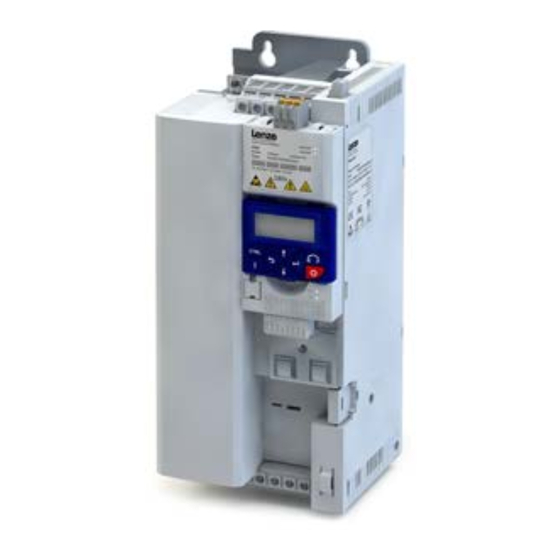
Page 15: Features
Product information Features Features The following figures give an overview of the elements and connections on the devices. Position, size and appearance of elements and connections may vary depending on the capacity and size of the equipment. Some equipment may be optional. Example of 0.25 kW ... - Page 16 Product information Features Example of 0.55 kW ... 4 kW PE connection X100 Mains connection/DC bus Relay output IT screw from 0.55 kW X2xx Network Option Network shield connection Option Network status LEDs Basic network settings DIP switch or rotary encoder switch Interface Diagnostic module Memory module...
- Page 17 Product information Features Example of 5.5 kW ... 11 kW PE connection X100 Mains connection/DC bus Relay output Network shield connection Option Network status LEDs X2xx Network Option Basic network settings Interface DIP switch or rotary encoder switch Diagnostic module Memory module Inverter status LEDs Control terminals...
- Page 18 Product information Features Example of 15 kW ... 22 kW X2xx Network X100 Mains connection/DC bus Option PE connection IT screw Relay output Network shield connection Network status LEDs Option Basic network settings DIP switch or rotary encoder switch Interface Diagnostic module Memory module Control terminals...
- Page 19 Product information Features Example of 30 kW ... 45 kW X100 PE connection Mains connection DC bus connection IT screw X2xx Network Relay output Option Network shield connection Network status LEDs Option Basic network settings DIP switch or rotary encoder switch Interface Diagnostic module Memory module...
- Page 20 Product information Features Example of 55 kW ... 75 kW Parking position - shield connection plate Motor cable PE connection X100 Mains connection DC bus connection IT screw Network X2xx Relay output Option Network shield connection Network status LEDs Option Basic network settings Interface DIP switch or rotary encoder switch...
- Page 21 Product information Features Example of 90 kW ... 110 kW Parking position shield connection motor cable PE connection X100 Network DC bus connection IT screw Network X2xx Relay output option Shield connection network LED status display network option Basic assignment Interface DIP switch or rotary encoder switch diagnostic module...
-
Page 22: The Modular System
Product information The modular system The concept The modular system The concept Thanks to its flexible concept and modular structure consisting of power unit, control unit and safety module, the inverter can be optimally adapted to the application. This provides the user with a flexible logistics concept - ordered as a complete inverter or single components. -
Page 23: Topologies / Network
CANopen® is a registered community trademark of the CAN user organisation CiA® (CAN in Automation e. V.). Device descriptions for the download: EDS files for Lenze devices The Modbus protocol is an open communication protocol based on a client/server architecture and developed for the communication with programmable logic controllers. -
Page 24: Ways Of Commissioning
Ideal for the parameterisation of simple applications such as a conveyor belt. • Ideal for the diagnostics of the inverter. • The Lenze SMART Keypad App can be found in the Google Play Store or in the Apple App Store. Android... -
Page 25: Functions
Product information Functions Overview Functions Overview With regard to their functionality, the inverters i550 are adapted to extensive applications. This is also reflected in the overall scope of the products. Functions Motor control Monitoring V/f characteristic control linear/square-law (VFC plus) Short circuit V/f characteristic control (VFC closed loop) Earth fault... -
Page 26: Motor Control Types
● ● m500 ● ● ● Lenze synchronous servo motors are not suitable for the use with inverters, e. g. the MCS, MCM or m850 types. Features Motor setting range Rated point 120 Hz Only possible with Lenze MF motors. - Page 27 Product information Features Motor setting range Rated point 87 Hz The rated motor torque is available up to 87 Hz. Compared to the 50-Hz operation, the setting range increases by 1.74 times. For this purpose, a motor with 230/400 V in star connection is driven by a 400-V inverter. The inverter must be dimensioned for a rated motor current of 230 V.
-
Page 28: Information On Project Planning
Detailed: In order to optimise the selection of the inverter and all drive components, it is worth to execute the detailed system dimensioning based on the physical requirements of the application. For this purpose, Lenze provides the «Drive Solution Designer» (DSD) design program. - Page 29 Information on project planning Project planning process Dimensioning Calculate range of adjustment and determine rated point Calculation Setting range L,max L,min Setting range Rated point 50 Hz ≤ 2.50 (20 - 50 Hz) 87 Hz Motor with integral fan ≤ 4.35 (20 - 87Hz) 120 Hz ≤...
- Page 30 Information on project planning Project planning process Dimensioning Determine the inverter based on the rated data for the "Light Duty" load characteristic Check Output current Continuous operation ≥ I / (k N,Mot H,INV TU,INV Overcurrent operation cycle 15 s ≥ I x 1.65 / (k N,Mot H,INV...
-
Page 31: Operation In Motor And Generator Mode
Information on project planning Project planning process Operation in motor and generator mode Final configuration Product extensions and accessories can be found here: Product extensions • ^ 157 Accessories • ^ 184 Operation in motor and generator mode The energy analysis differs between operation in motor mode and generator mode. During operation in motor mode, the energy flows from the supplying mains via the inverter to the motor which converts electrical energy into mechanical energy (e. -
Page 32: Overcurrent Operation
Information on project planning Project planning process Overcurrent operation Overcurrent operation The inverters can be driven at higher amperages beyond the rated current if the duration of this overcurrent operation is time limited. Two utilisation cycles of 15 s and 180 s are defined. Within these utilisation cycles, an overcurrent is possible for a certain time if afterwards an accordingly long recovery phase takes place. - Page 33 Information on project planning Project planning process Overcurrent operation Inverter load characteristics The inverter has two different load characteristics: "Light Duty" and "Heavy Duty". The "Light Duty" load characteristic allows for a higher output current with restrictions regarding overload capacity, ambient temperature and switching frequency. This allows the motor required for the application to be driven by a less powerful inverter.
-
Page 34: Safety Instructions
The procedural notes and circuit details described are only proposals. It is up to the user to check whether they can be adapted to the particular applications. Lenze does not take any responsibility for the suitability of the procedures and circuit proposals described. -
Page 35: Application As Directed
Due to the many areas of liability that may arise when handling these applications, the following declaration of principle applies: The inverters from Lenze are sold without warranty of suitability for a particular purpose or warranty of suitability for use in explosion-proof motors. Lenze... -
Page 36: Handling
Information on project planning Safety instructions Handling Handling Transport, storage Observe the notes regarding transport, storage and correct handling. Ensure proper handling and avoid mechanical stress. Do not bend any components and do not change any insulation distances during transport or handling. Do not touch any electronic components and contacts. Inverters contain electrostatically sensitive components which can easily be damaged by inappropriate handling. - Page 37 Information on project planning Safety instructions Handling Disposal In accordance with the current provisions, Lenze products and accessories have to be disposed of by means of professional recycling. Lenze products contain contain recyclable raw material such as metal, plastics and electronic components.
-
Page 38: Residual Hazards
Information on project planning Safety instructions Residual hazards Residual hazards Even if notes given are taken into consideration and protective measures are implemented, the occurrence of residual risks cannot be fully prevented. The user must take the residual hazards mentioned into consideration in the risk assessment for his/her machine/system. - Page 39 Information on project planning Safety instructions Residual hazards Risks when exchanging devices WARNING! Incorrect handling of devices. Device damage. ▶ Check the compatibility of the devices before exchanging. ▶ Check the memory cards of the devices before exchanging. ▶ Set the safety address. ▶...
-
Page 40: Control Cabinet Structure
Information on project planning Control cabinet structure Arrangement of components Control cabinet structure Control cabinet requirements Protection against electromagnetic interferences • Compliance with the ambient conditions of the installed components • Mounting plate requirements The mounting plate must be electrically conductive. •... -
Page 41: Cables
Information on project planning Control cabinet structure Earthing concept Cables Requirements The cables used must correspond to the requirements at the location (e. g. EN 60204−1, • UL). The cable cross-section must be dimensioned for the assigned fusing. Observe national •... -
Page 42: Emc-Compliant Installation
Information on project planning Control cabinet structure EMC-compliant installation EMC-compliant installation The drive system (inverter and drive) meet the EMC Directive 2014/30/EU if it is installed according to the guidelines of CE-typical drive systems. The structure in the control cabinet must support the EMC-compliant installation with shielded motor cables. - Page 43 • separately from the motor cable. In Lenze system cables, the cable for brake control is integrated into the motor cable. If this cable is not required for brake control, it can also be used to connect the motor temperature monitoring up to a length of 50 m.
- Page 44 Information on project planning Control cabinet structure EMC-compliant installation Detecting and eliminating EMC interferences Trouble Cause Remedy Interferences of analog setpoints of your own Unshielded motor cable has been used Use shielded motor cable or other devices and measuring systems Shield contact is not extensive enough Carry out optimal shielding as specified Shield of the motor cable is interrupted, e.
-
Page 45: Information On Mechanical Installation
Information on mechanical installation Important notes Information on mechanical installation Important notes After being mounted ,the safety module cannot be removed anymore! Measures for cooling during operation Ensure unimpeded ventilation of cooling air and outlet of exhaust air. • If the cooling air is polluted (fluff, (conductive) dust, soot, grease, aggressive gases), take •... -
Page 46: Preparation
Information on mechanical installation Preparation Preparation Further data and information for mechanical mounting: 4Control cabinet structure ^ 40 4Dimensions ^ 146 The scope of supply of the inverter comprises mounting instructions. They describe technical data and information on mechanical and electrical installation. -
Page 47: Information On Electrical Installation
Information on electrical installation Information on electrical installation Important notes DANGER! Electrical voltage Possible consequences: Death or severe injuries ▶ Any work on the inverter must only be carried out in the deenergised state. ▶ Inverter up to 45 kW: After switching off the mains voltage, wait for at least 3 min before you start working. - Page 48 Possible consequences: The filters may be destroyed when an earth fault occurs. Possible consequences: Monitoring of the IT system may be triggered. ▶ Do not use mains filters and RFI filters from Lenze in IT systems. ▶ Before using the inverter in the IT system, remove the IT screws.
-
Page 49: Preparation
Information on electrical installation Preparation You have to install the devices into housings (e. g. control cabinets) to comply with valid regulations. Stickers with warning notes must be displayed prominently and close to the device. Preparation Further data and information for electrical installation: 4EMC-compliant installation ^ 42 4Standards and operating conditions... -
Page 50: Connection According To Ul
Information on electrical installation Connection according to UL Connection according to UL WARNING! ▶ UL marking ▶ Suitable for motor group installation or use on a circuit capable of delivering not more than the rms symmetrical amperes (SCCR) of the drive at its rated voltage. ▶... - Page 51 Information on electrical installation Connection according to UL Branch Circuit Protection (BCP) with Short Circuit Current Ratings (SCCR) with Standard Fuses. (Tested per UL61800-5-1, reference UL file E132659) These devices are suitable for motor group installation when used with Standard Fuses. For single motor installation, if the fuse value indicated is higher than 400% of the motor current (FLA), the fuse value has to be calculated.
- Page 52 Information on electrical installation Connection according to UL Branch Circuit Protection (BCP) with Short Circuit Current Rating (SCCR) for Semiconductor Fuses and Circuit Breaker. (Tested per UL61800-5-1, reference UL file E132659) These devices are suitable for motor group installation when used with Circuit Breakers. For single motor installation, if the fuse value indicated is higher than 400% of the motor current (FLA), the fuse value has to be calculated.
-
Page 53: Mains Connection
Information on electrical installation Mains connection Mains connection The following should be considered for the mains connection of inverters: Single inverters are either directly connected to the AC system or via upstream filters. RFI filters are already integrated in many inverters. Depending on the requirements, mains chokes or mains filters can be used. -
Page 54: 1-Phase Mains Connection 120 V
Information on electrical installation Mains connection 1-phase mains connection 120 V 1-phase mains connection 120 V The connection plan is valid for the inverters i550-Cxxx/120-1. The inverters i550-Cxxx/120-1 do not have an integrated RFI filter in the AC mains supply. In order to meet the EMC requirements according to EN 61800−3, an external EMC filter according to IEC EN 60939 must be used. -
Page 55: 1-Phase Mains Connection 230/240 V
Information on electrical installation Mains connection 1-phase mains connection 230/240 V 1-phase mains connection 230/240 V The connection plan is valid for the inverters i550-Cxxx/230-1. 3/N/ PE 3/N/ PE 2/N/ PE 400 V 208 V ... 240 V 208 V ... 240 V …... - Page 56 Information on electrical installation Mains connection 1-phase mains connection 230/240 V The connection plan is valid for the inverters i550-Cxxx/230-2. The inverters i550-Cxxx/230-2 do not have an integrated RFI filter in the AC mains supply. In order to meet the EMC requirements according to EN 61800−3, an external EMC filter according to IEC EN 60939 must be used.
-
Page 57: 3-Phase Mains Connection 230/240 V
Information on electrical installation Mains connection 3-phase mains connection 230/240 V 3-phase mains connection 230/240 V The connection plan is valid for the inverters i550-Cxxx/230-3. The inverters i550-Cxxx/230-3 do not have an integrated RFI filter in the AC mains supply. In order to meet the EMC requirements according to EN 61800−3, an external EMC filter according to IEC EN 60939 must be used. -
Page 58: 3-Phase Mains Connection 230/240 V "Light Duty
Information on electrical installation Mains connection 3-phase mains connection 230/240 V "Light Duty" The connection plan is valid for the inverters i550-Cxxx/230-2. The inverters i550-Cxxx/230-2 do not have an integrated RFI filter in the AC mains supply. In order to meet the EMC requirements according to EN 61800−3, an external EMC filter according to IEC EN 60939 must be used. -
Page 59: 3-Phase Mains Connection 400 V
Information on electrical installation Mains connection 3-phase mains connection 400 V "Light Duty" 3-phase mains connection 400 V The connection plan is valid for the inverters i550-Cxxx/400-3. 3/N/ PE AC 400 V … 3/ PE 340 V ... 528 V 45 Hz ... -
Page 60: 3-Phase Mains Connection 480 V
Information on electrical installation Mains connection 3-phase mains connection 480 V "Light Duty" 3-phase mains connection 480 V The connection plan is valid for the inverters i550-Cxxx/400-3. 3/N/ PE AC 480 V … 3/ PE 340 V ... 528 V 45 Hz ... -
Page 61: Motor Connection
Information on electrical installation Motor connection Motor connection Switching in the motor cable Switching on the motor side of the inverter is permissible: For safety shutdown (emergency stop). In case several motors are driven by one inverter (only in V/f operating mode). Please note the following: The switching elements on the motor side must be dimensioned for with the maximum occurring load. -
Page 62: Connection To The It System
Information on electrical installation Connection to the IT system Connection to the IT system For a trouble-free operation on the IT system, observe the following measures: Connect an isolating transformer upstream. • Remove the IT screws. Otherwise the monitoring devices of the IT system will be triggered •... - Page 63 Information on electrical installation Connection to the IT system I55AE315F, I55AE318F, I55AE322F I55AE330F, I55AE337F, I55AE345F...
-
Page 64: Connection Of Motor Temperature Monitoring
Information on electrical installation Connection of motor temperature monitoring I55AE355F, I55AE375F, I55AE390F, I55AE411F Connection of motor temperature monitoring If the terminal X109 is used, e. g. to connect an external PTC thermistor (PTC) or a thermal contact, ensure at least one basic insulation to the potentials of the motor, mains and control terminals to not restrict the protective separation of the control terminals. -
Page 65: Brake Resistor Connection
Information on electrical installation Brake resistor connection Brake resistor connection If the wiring of the brake resistor can be kept short, twisting the wires is sufficient. Up to a cable length of 0.5 m, this applies to the cable for the brake resistor and that of the temperature monitoring. -
Page 66: Dc-Bus Connection
Information on electrical installation Control connections DC-bus connection Rated mains voltage DC voltage range DC 450 V - 0 % ... 750 V + 0 % Control connections Terminal description Control terminals Connection Connection type Pluggable spring terminal Max. cable cross-section mm²... -
Page 67: Networks
Information on electrical installation Networks EtherCAT Networks CANopen Typical topologies Line X216 X216 X216 X216 Terminal description CANopen Connection X216 Connection type pluggable double spring terminal Max. cable cross-section mm² Max. cable cross-section Stripping length Stripping length inch 0.39 Tightening torque Tightening torque lb-in Required tool... -
Page 68: Ethernet/Ip
Information on electrical installation Networks Modbus RTU EtherNet/IP Typical topologies Line Tree Ring Scanner Switch Adapter Bus-related information Name EtherNet/IP Communication medium Ethernet 10 Mbps, 100 Mbps, half duplex, full duplex Connection of the inverter to an EtherNet/IP network Connection system RJ45 Status display 2 LEDs... -
Page 69: Modbus Tcp
Information on electrical installation Networks POWERLINK Modbus TCP Typical topologies Line Tree Master Switch Slave Bus-related information Name Modbus TCP Communication medium Ethernet 10 Mbps, 100 Mbps, half duplex, full duplex Connection of the inverter to a Modbus TCP network Connection system RJ45 Status display... -
Page 70: Profibus
Information on electrical installation Networks PROFINET PROFIBUS Typical topologies Line with repeater Master Repeater Slave Activated bus terminating resistor Sub D socket 9-pin - X226 View Assignment Description Shield Additional shield connection n.c. RxD/TxD-P Data line-B (received data/transmitted data +) Request To Send (received data/transmitted data, no differential signal) M5V2 Reference potential (bus terminating resistor -) -
Page 71: Io-Link
Information on electrical installation Networks IO-Link IO-Link Typical topologies Tree Master Device Terminal description IO link Connection X316 Connection type pluggable double spring terminal Max. cable cross-section mm² Max. cable cross-section Stripping length Stripping length inch 0.39 Tightening torque Tightening torque lb-in Required tool 0.4 x 2.5... -
Page 72: Functional Safety
Information on electrical installation Functional safety Functional safety DANGER! Improper installation of the safety engineering system can cause an uncontrolled starting action of the drives. Possible consequence: Death or severe injuries ▶ Safety engineering systems may only be installed and commissioned by qualified personnel. ▶... -
Page 73: Important Notes
Information on electrical installation Functional safety Important notes Important notes Standards Safety regulations are confirmed by laws and other governmental guidelines and measures and the prevailing opinion among experts, e.g. by technical regulations. The regulations and rules to be applied must be observed in accordance with the application. Risk assessment This documentation can only accentuate the need for a risk assessment. -
Page 74: Basic Safety - Sto
Information on electrical installation Functional safety Basic Safety - STO Basic Safety - STO DANGER! With the "Safe torque off" (STO) function, no “emergency‑stop" can be executed according to EN 60204−1 without additional measures. There is no electrical isolation between the motor and inverter and no service switch or maintenance switch! Possible consequences: Death or severe injuries ▶... -
Page 75: Connection Diagram
Information on electrical installation Functional safety Basic Safety - STO Connection diagram Active sensors Active sensor - example of lightgrid Passive sensors +24 V DC 24 V SELV/PELV Passive sensor Passive sensor Safety switching device Passive sensors - further examples Emergency stop (STO) SS1c/SS1-t Emergency stop (SS1c/SS1-t) -
Page 76: Terminal Data
Information on electrical installation Functional safety Basic Safety - STO Terminal data Specification Unit min. typ. max. SIA, SIB LOW signal HIGH signal Running time Clear time Input current SIA Input current SIB Input peak current Test pulse duration Test pulse interval Reference potential for SIA and SIB Terminal description Basic Safety STO... -
Page 77: Technical Data
Technical data EMC data Technical data Standards and operating conditions Conformities/approvals Conformity 2014/35/EU Low-Voltage Directive 2014/30/EU EMC Directive (reference: CE-typical drive system) TR CU 004/2011 Eurasian conformity: safety of low voltage equipment Eurasian conformity: electromagnetic compatibility of technical TR CU 020/2011 means Restrictions for the use of specific hazardous materials in electric RoHS... -
Page 78: Motor Connection
Technical data Standards and operating conditions Electrical supply conditions Motor connection Requirements to the shielded motor cable Capacitance per unit length C-core-core/C-core-shield < 75/150 pF/m ≤ 2.5 mm² / AWG 14 C-core-core/C-core-shield < 150/300 pF/m ≥ 4 mm² / AWG 12 Electric strength Uo = r.m.s. -
Page 79: Certification Of The Integrated Safety
EN 61800−5−2: Adjustable speed electrical power drive systems − Part 5−2: Safety • requirements − functional safety EN 62061: Safety of machinery − functional safety of safety-related electrical/electronic/ • programmable electronic systems Declarations of Conformity and certificates can be found on the internet at http://www.Lenze.com... - Page 80 Technical data 1-phase mains connection 120 V 1-phase mains connection 120 V EMC filters are not integrated in inverters for this mains connection.
-
Page 81: 1-Phase Mains Connection 120 V
The output currents apply to these operating conditions: At a switching frequency of 2 kHz or 4 kHz: Max. ambient temperature 45°C. • At a switching frequency of 8 kHz or 16 kHz: Max. ambient temperature 40 °C. • Inverters i550-C0.25/120-1 i550-C0.37/120-1 i550-C0.75/120-1 i550-C1.1/120-1 Rated power 0.25 0.37... -
Page 82: Fusing Data
Earth-leakage circuit breaker Characteristics Max. rated Characteristics Max. rated current current i550-C0.25/120-1 gG/gL or gRL ≥ 30 mA, type A or B i550-C0.37/120-1 gG/gL or gRL ≥ 30 mA, type A or B i550-C0.75/120-1 gG/gL or gRL ≥ 30 mA, type A or B i550-C1.1/120-1... -
Page 83: 1-Phase Mains Connection 230/240 V
Technical data 1-phase mains connection 230/240 V 1-phase mains connection 230/240 V When selecting the inverters, please note: EMC filters are integrated in the i550-Cxxx/230-1 inverters. EMC filters are not integrated in the inverters i550- Cxxx/230-2. -
Page 84: Rated Data
Technical data 1-phase mains connection 230/240 V Rated data Rated data The output currents apply to these operating conditions: At a switching frequency of 2 kHz or 4 kHz: Max. ambient temperature 45°C. • At a switching frequency of 8 kHz or 16 kHz: Max. ambient temperature 40 °C. •... - Page 85 Technical data 1-phase mains connection 230/240 V Rated data Inverters i550-C0.55/230-1 i550-C0.55/230-2 i550-C0.75/230-1 i550-C0.75/230-2 Rated power 0.55 0.55 0.75 0.75 Rated power 0.75 0.75 Mains voltage range 1/PE AC 170 V ... 264 V, 45 Hz ... 65 Hz Output voltage 3 AC 0-230/240 V Rated mains current without mains choke...
- Page 86 Technical data 1-phase mains connection 230/240 V Rated data Inverters i550-C1.1/230-1 i550-C1.1/230-2 i550-C1.5/230-1 i550-C1.5/230-2 Rated power Rated power Mains voltage range 1/PE AC 170 V ... 264 V, 45 Hz ... 65 Hz Output voltage 3 AC 0-230/240 V Rated mains current without mains choke 14.3 14.3...
- Page 87 Technical data 1-phase mains connection 230/240 V Rated data Inverters i550-C2.2/230-1 i550-C2.2/230-2 Rated power Rated power Mains voltage range 1/PE AC 170 V ... 264 V, 45 Hz ... 65 Hz Output voltage 3 AC 0-230/240 V Rated mains current without mains choke 22.5 22.5...
-
Page 88: Fusing Data
Technical data 1-phase mains connection 230/240 V Terminal data Fusing data EN 60204-1 Inverters Fuse Circuit breaker Earth-leakage circuit breaker Characteristics Max. rated Characteristics Max. rated current current i550-C0.25/230-1 gG/gL or gRL ≥ 30 mA, type A or B i550-C0.25/230-2 gG/gL or gRL ≥... -
Page 89: Brake Resistors
Technical data 1-phase mains connection 230/240 V Mains chokes Brake resistors Inverters Brake resistor Order code Rated resistance Rated power Thermal capacity Dimensions (h x b x Weight Ω i550-C0.25/230-1 i550-C0.25/230-2 ERBM180R050W 175 x 21 x 40 0.28 i550-C0.37/230-1 i550-C0.37/230-2 i550-C0.55/230-1 i550-C0.55/230-2 ERBM100R100W... -
Page 90: Rfi Filters / Mains Filters
Technical data 1-phase mains connection 230/240 V RFI filters / Mains filters RFI filters / Mains filters Basic information on RFI filters, mains filters and EMC: from ^ 192 EMC filters can be used both in the side structure and in the substructure. Maximum motor cable lengths and FI operation Mains connection 1-phase, 230 V... - Page 91 Technical data 1-phase mains connection 230/240 V RFI filters / Mains filters Short Distance Inverters RFI filter Order code Output current Dimensions (h x b x d) Weight i550-C0.25/230-1 i550-C0.37/230-1 I0FAE175B100S0000S 276 x 60 x 50 0.85 i550-C0.55/230-1 i550-C0.75/230-1 i550-C1.1/230-1 i550-C1.5/230-1 I0FAE222B100S0000S 22.5...
-
Page 92: 3-Phase Mains Connection 230/240 V
Technical data 3-phase mains connection 230/240 V 3-phase mains connection 230/240 V EMC filters are not integrated in inverters for this mains connection. -
Page 93: Rated Data
Technical data 3-phase mains connection 230/240 V Rated data Rated data The output currents apply to these operating conditions: At a switching frequency of 2 kHz or 4 kHz: Max. ambient temperature 45°C. • At a switching frequency of 8 kHz or 16 kHz: Max. ambient temperature 40 °C. •... - Page 94 Technical data 3-phase mains connection 230/240 V Rated data Inverters i550-C1.1/230-2 i550-C1.5/230-2 i550-C2.2/230-2 i550-C5.5/230-3 Rated power Rated power Mains voltage range 3/PE AC 170 V ... 264 V, 45 Hz ... 65 Hz Output voltage 3 AC 0-230/240 V Rated mains current without mains choke 13.6 28.8...
-
Page 95: Fusing Data
Technical data 3-phase mains connection 230/240 V Terminal data Fusing data EN 60204-1 Inverters Fuse Circuit breaker Earth-leakage circuit breaker Characteristics Max. rated Characteristics Max. rated current current i550-C0.25/230-2 gG/gL or gRL ≥ 30 mA, type B i550-C0.37/230-2 gG/gL or gRL ≥... -
Page 96: Brake Resistors
Technical data 3-phase mains connection 230/240 V Mains chokes Brake resistors Inverters Brake resistor Order code Rated resistance Rated power Thermal capacity Dimensions (h x b x Weight Ω i550-C0.25/230-2 ERBM180R050W 175 x 21 x 40 0.28 i550-C0.37/230-2 i550-C0.55/230-2 ERBM100R100W 240 x 80 x 95 0.37 i550-C0.75/230-2... -
Page 97: 3-Phase Mains Connection 230/240 V "Light Duty
Technical data 3-phase mains connection 230/240 V "Light Duty" Rated data 3-phase mains connection 230/240 V "Light Duty" Rated data EMC filters are not integrated in inverters for this mains connection. - Page 98 Technical data 3-phase mains connection 230/240 V "Light Duty" Rated data The output currents apply to these operating conditions: At a switching frequency of 2 kHz or 4 kHz: Ambient temperature above 40 °C with a rated • output current reduced by 2.5 %/°C. If the load characteristic "Light Duty"...
-
Page 99: Fusing Data
Technical data 3-phase mains connection 230/240 V "Light Duty" Mains chokes Fusing data EN 60204-1 Inverters Fuse Circuit breaker Earth-leakage circuit breaker Characteristics Max. rated Characteristics Max. rated current current i550-C4.0/230-3 gG/gL or gRL ≥ 300 mA, type B i550-C5.5/230-3 gG/gL or gRL ≥... -
Page 100: 3-Phase Mains Connection 400 V
Technical data 3-phase mains connection 400 V Rated data 3-phase mains connection 400 V Rated data The output currents apply to these operating conditions: At a switching frequency of 2 kHz or 4 kHz: Max. ambient temperature 45°C. • At a switching frequency of 8 kHz or 16 kHz: Max. ambient temperature 40 °C. •... - Page 101 Technical data 3-phase mains connection 400 V Rated data Inverters i550-C1.5/400-3 i550-C2.2/400-3 i550-C3.0/400-3 i550-C4.0/400-3 Rated power Rated power Mains voltage range 3/PE AC 340 V ... 528 V, 45 Hz ... 65 Hz Output voltage 3 AC 0-400/480 V Rated mains current without mains choke 12.5 with mains choke...
- Page 102 Technical data 3-phase mains connection 400 V Rated data Inverters i550-C5.5/400-3 i550-C7.5/400-3 i550-C11/400-3 i550-C15/400-3 Rated power Rated power Mains voltage range 3/PE AC 340 V ... 528 V, 45 Hz ... 65 Hz Output voltage 3 AC 0-400/480 V Rated mains current without mains choke 17.2 28.4...
- Page 103 Technical data 3-phase mains connection 400 V Rated data Inverters i550-C18/400-3 i550-C22/400-3 i550-C30/400-3 i550-C37/400-3 Rated power 18.5 Rated power Mains voltage range 3/PE AC 340 V ... 528 V, 45 Hz ... 65 Hz Output voltage 3 AC 0-400/480 V Rated mains current without mains choke 48.4...
- Page 104 Technical data 3-phase mains connection 400 V Rated data Inverters i550-C45/400-3 i550-C55/400-3 i550-C75/400-3 i550-C90/400-3 Rated power Rated power Mains voltage range 3/PE AC 340 V ... 528 V, 45 Hz ... 65 Hz Output voltage 3 AC 0-400/480 V Rated mains current without mains choke with mains choke Apparent output power...
- Page 105 Technical data 3-phase mains connection 400 V Rated data Inverters i550-C110/400-3 Rated power Rated power Mains voltage range 3/PE AC 340 V ... 528 V, 45 Hz ... 65 Hz Output voltage 3 AC 0-400/480 V Rated mains current without mains choke with mains choke Apparent output power Rated output current...
-
Page 106: Fusing Data
Technical data 3-phase mains connection 400 V Fusing data Fusing data EN 60204-1 Inverters Fuse Circuit breaker Earth-leakage circuit breaker Characteristics Max. rated Characteristics Max. rated current current i550-C0.37/400-3 gG/gL or gRL ≥ 30 mA, type B i550-C0.55/400-3 gG/gL or gRL ≥... -
Page 107: Terminal Data
Technical data 3-phase mains connection 400 V Terminal data Terminal data i550-Cxxxx/400-3 Inverters 0.37 ... 2.2 3.0 ... 4.0 7.5 ... 11 15 ... 22 Connection X100 mains connection Connection type Pluggable screw terminal Screw terminal Max. cable cross-section mm² Stripping length Tightening torque Required tool... -
Page 108: Brake Resistors
Technical data 3-phase mains connection 400 V Brake resistors Brake resistors Inverters Brake resistor Order code Rated resistance Rated power Thermal capacity Dimensions (h x b x Weight Ω i550-C0.37/400-3 i550-C0.55/400-3 ERBM390R100W 235 x 21 x 40 0.37 i550-C0.75/400-3 ERBP180R200W 240 x 41 x 122 i550-C1.1/400-3 ERBP180R300W... -
Page 109: Mains Chokes
Technical data 3-phase mains connection 400 V Mains chokes Mains chokes Inverters Mains choke Order code Number of phases Output current Inductance Dimensions (h x b x Weight i550-C0.37/400-3 EZAELN3002B203 19.6 0.52 56 x 77 x 100 i550-C0.55/400-3 EZAELN3002B153 14.7 0.53 i550-C0.75/400-3 i550-C1.1/400-3... -
Page 110: Rfi Filters / Mains Filters
Technical data 3-phase mains connection 400 V RFI filters / Mains filters RFI filters / Mains filters Basic information on RFI filters, mains filters and EMC: from ^ 192 EMC filters can be used both in the side structure and in the substructure. Maximum motor cable lengths and FI operation Mains connection 3-phase, 400 V/480 V... - Page 111 Technical data 3-phase mains connection 400 V RFI filters / Mains filters Mains connection 3-phase, 400 V/480 V Inverter i550-C7.5/400-3 i550-C15/400-3 i550-C30/400-3 i550-C55/400-3 i550-C11/400-3 i550-C18/400-3 i550-C37/400-3 i550-C75/400-3 i550-C22/400-3 i550-C45/400-3 Without RFI filter Without EMC Max. Shielded motor category cable length Thermal limitation Max.
-
Page 112: Sine Filter
Technical data 3-phase mains connection 400 V Sine filter Long Distance Inverters RFI filter Order code Output current Dimensions (h x b x d) Weight i550-C0.37/400-3 i550-C0.55/400-3 I0FAE175F100D0000S 276 x 60 x 50 i550-C0.75/400-3 i550-C1.1/400-3 i550-C1.5/400-3 I0FAE222F100D0000S i550-C2.2/400-3 346 x 60 x 50 i550-C3.0/400-3 I0FAE240F100D0000S 12.5... -
Page 113: 3-Phase Mains Connection 400 V "Light Duty
Technical data 3-phase mains connection 400 V "Light Duty" Rated data 3-phase mains connection 400 V "Light Duty" Rated data The output currents apply to these operating conditions: At a switching frequency of 2 kHz or 4 kHz: Ambient temperature above 40 °C with a rated •... - Page 114 Technical data 3-phase mains connection 400 V "Light Duty" Rated data Inverters i550-C11/400-3 i550-C15/400-3 i550-C18/400-3 i550-C22/400-3 Rated power 18.5 Rated power Mains voltage range 3/PE AC 340 V ... 528 V, 45 Hz ... 65 Hz Output voltage 3 AC 0-400/480 V Rated mains current without mains choke with mains choke...
- Page 115 Technical data 3-phase mains connection 400 V "Light Duty" Rated data Inverters i550-C30/400-3 i550-C37/400-3 i550-C45/400-3 i550-C55/400-3 Rated power Rated power Mains voltage range 3/PE AC 340 V ... 528 V, 45 Hz ... 65 Hz Output voltage 3 AC 0-400/480 V Rated mains current without mains choke with mains choke...
- Page 116 Technical data 3-phase mains connection 400 V "Light Duty" Rated data Inverters i550-C75/400-3 i550-C90/400-3 i550-C110/400-3 Rated power Rated power Mains voltage range 3/PE AC 340 V ... 528 V, 45 Hz ... 65 Hz Output voltage 3 AC 0-400/480 V Rated mains current without mains choke with mains choke...
-
Page 117: Fusing Data
Technical data 3-phase mains connection 400 V "Light Duty" Fusing data Fusing data EN 60204-1 Inverters Fuse Circuit breaker Earth-leakage circuit breaker Characteristics Max. rated Characteristics Max. rated current current i550-C3.0/400-3 gG/gL or gRL ≥ 30 mA, type B i550-C4.0/400-3 gG/gL or gRL ≥... -
Page 118: Terminal Data
Technical data 3-phase mains connection 400 V "Light Duty" Terminal data Terminal data i550-Cxxxx/400-3 Inverters 4.0 ... 5.5 11 ... 15 18.5 ... 30 37 ... 55 Connection X100 mains connection Connection type Pluggable screw Screw terminal terminal Max. cable cross-section mm²... -
Page 119: Brake Resistors
Technical data 3-phase mains connection 400 V "Light Duty" Brake resistors Brake resistors Inverters Brake resistor Order code Rated resistance Rated power Thermal capacity Dimensions (h x b x Weight Ω ERBP082R200W 320 x 41 x 122 i550-C3.0/400-3 ERBS082R780W 666 x 124 x 122 ERBP047R200W 320 x 41 x 122 i550-C4.0/400-3... -
Page 120: Mains Chokes
Technical data 3-phase mains connection 400 V "Light Duty" Mains chokes Mains chokes Inverters Mains choke Order code Number of phases Output current Inductance Dimensions (h x b x Weight i550-C3.0/400-3 EZAELN3010B292 2.94 85 x 120 x 140 i550-C4.0/400-3 EZAELN3016B182 1.84 95 x 120 x 140 i550-C5.5/400-3... -
Page 121: Rfi Filters / Mains Filters
Technical data 3-phase mains connection 400 V "Light Duty" RFI filters / Mains filters RFI filters / Mains filters Basic information on RFI filters, mains filters and EMC: from ^ 192 EMC filters can be used both in the side structure and in the substructure. Maximum motor cable lengths and FI operation Mains connection 3-phase, 400 V/480 V, Light Duty... -
Page 122: Sine Filter
Technical data 3-phase mains connection 400 V "Light Duty" Sine filter Long Distance Inverters RFI filter Order code Output current Dimensions (h x b x d) Weight i550-C3.0/400-3 I0FAE240F100D0000S 12.5 346 x 60 x 50 1.35 i550-C4.0/400-3 I0FAE255F100D0001S 18.3 346 x 90 x 60 i550-C5.5/400-3 i550-C7.5/400-3 I0FAE311F100D0000S... -
Page 123: 3-Phase Mains Connection 480 V
Technical data 3-phase mains connection 480 V Rated data 3-phase mains connection 480 V Rated data The output currents apply to these operating conditions: At a switching frequency of 2 kHz or 4 kHz: Max. ambient temperature 45°C. • At a switching frequency of 8 kHz or 16 kHz: Max. ambient temperature 40 °C. •... - Page 124 Technical data 3-phase mains connection 480 V Rated data Inverters i550-C1.5/400-3 i550-C2.2/400-3 i550-C3.0/400-3 i550-C4.0/400-3 Rated power Rated power Mains voltage range 3/PE AC 340 V ... 528 V, 45 Hz ... 65 Hz Output voltage 3 AC 0-400/480 V Rated mains current without mains choke 10.5 with mains choke...
- Page 125 Technical data 3-phase mains connection 480 V Rated data Inverters i550-C5.5/400-3 i550-C7.5/400-3 i550-C11/400-3 i550-C15/400-3 Rated power Rated power Mains voltage range 3/PE AC 340 V ... 528 V, 45 Hz ... 65 Hz Output voltage 3 AC 0-400/480 V Rated mains current without mains choke 14.3 16.6...
- Page 126 Technical data 3-phase mains connection 480 V Rated data Inverters i550-C18/400-3 i550-C22/400-3 i550-C30/400-3 i550-C37/400-3 Rated power 18.5 Rated power Mains voltage range 3/PE AC 340 V ... 528 V, 45 Hz ... 65 Hz Output voltage 3 AC 0-400/480 V Rated mains current without mains choke 40.3...
- Page 127 Technical data 3-phase mains connection 480 V Rated data Inverters i550-C45/400-3 i550-C55/400-3 i550-C75/400-3 i550-C90/400-3 Rated power Rated power Mains voltage range 3/PE AC 340 V ... 528 V, 45 Hz ... 65 Hz Output voltage 3 AC 0-400/480 V Rated mains current without mains choke with mains choke 66.7...
- Page 128 Technical data 3-phase mains connection 480 V Rated data Inverters i550-C110/400-3 Rated power Rated power Mains voltage range 3/PE AC 340 V ... 528 V, 45 Hz ... 65 Hz Output voltage 3 AC 0-400/480 V Rated mains current without mains choke with mains choke Apparent output power Rated output current...
-
Page 129: Fusing Data
Technical data 3-phase mains connection 480 V Fusing data Fusing data EN 60204-1 Inverters Fuse Circuit breaker Earth-leakage circuit breaker Characteristics Max. rated Characteristics Max. rated current current i550-C0.37/400-3 gG/gL or gRL ≥ 30 mA, type B i550-C0.55/400-3 gG/gL or gRL ≥... -
Page 130: Terminal Data
Technical data 3-phase mains connection 480 V Terminal data Terminal data i550-Cxxxx/400-3 Inverters 0.37 ... 2.2 3.0 ... 4.0 7.5 ... 11 15 ... 22 Connection X100 mains connection Connection type Pluggable screw terminal Screw terminal Max. cable cross-section mm² Stripping length Tightening torque Required tool... -
Page 131: Brake Resistors
Technical data 3-phase mains connection 480 V Brake resistors Brake resistors Inverters Brake resistor Order code Rated resistance Rated power Thermal capacity Dimensions (h x b x Weight Ω i550-C0.37/400-3 i550-C0.55/400-3 ERBM390R100W 235 x 21 x 40 0.37 i550-C0.75/400-3 ERBP180R200W 240 x 41 x 122 i550-C1.1/400-3 ERBP180R300W... -
Page 132: Mains Chokes
Technical data 3-phase mains connection 480 V Mains chokes Mains chokes Inverters Mains choke Order code Number of phases Output current Inductance Dimensions (h x b x Weight i550-C0.37/400-3 EZAELN3002B203 19.6 0.52 56 x 77 x 100 i550-C0.55/400-3 EZAELN3002B153 14.7 0.53 i550-C0.75/400-3 i550-C1.1/400-3... -
Page 133: Rfi Filters / Mains Filters
Technical data 3-phase mains connection 480 V RFI filters / Mains filters RFI filters / Mains filters Basic information on RFI filters, mains filters and EMC: from ^ 192 EMC filters can be used both in the side structure and in the substructure. Maximum motor cable lengths and FI operation Mains connection 3-phase, 400 V/480 V... - Page 134 Technical data 3-phase mains connection 480 V RFI filters / Mains filters Mains connection 3-phase, 400 V/480 V Inverter i550-C7.5/400-3 i550-C15/400-3 i550-C30/400-3 i550-C55/400-3 i550-C11/400-3 i550-C18/400-3 i550-C37/400-3 i550-C75/400-3 i550-C22/400-3 i550-C45/400-3 Without RFI filter Without EMC Max. Shielded motor category cable length Thermal limitation Max.
- Page 135 Technical data 3-phase mains connection 480 V RFI filters / Mains filters Long Distance Inverters RFI filter Order code Output current Dimensions (h x b x d) Weight i550-C0.37/400-3 i550-C0.55/400-3 I0FAE175F100D0000S 276 x 60 x 50 i550-C0.75/400-3 i550-C1.1/400-3 i550-C1.5/400-3 I0FAE222F100D0000S i550-C2.2/400-3 346 x 60 x 50 i550-C3.0/400-3...
-
Page 136: 3-Phase Mains Connection 480 V "Light Duty
Technical data 3-phase mains connection 480 V "Light Duty" Rated data 3-phase mains connection 480 V "Light Duty" Rated data The output currents apply to these operating conditions: At a switching frequency of 2 kHz or 4 kHz: Ambient temperature above 40 °C with a rated •... - Page 137 Technical data 3-phase mains connection 480 V "Light Duty" Rated data Inverters i550-C11/400-3 i550-C15/400-3 i550-C18/400-3 i550-C22/400-3 Rated power 18.5 Rated power Mains voltage range 3/PE AC 340 V ... 528 V, 45 Hz ... 65 Hz Output voltage 3 AC 0-400/480 V Rated mains current without mains choke with mains choke...
- Page 138 Technical data 3-phase mains connection 480 V "Light Duty" Rated data Inverters i550-C30/400-3 i550-C37/400-3 i550-C45/400-3 i550-C55/400-3 Rated power Rated power Mains voltage range 3/PE AC 340 V ... 528 V, 45 Hz ... 65 Hz Output voltage 3 AC 0-400/480 V Rated mains current without mains choke with mains choke...
- Page 139 Technical data 3-phase mains connection 480 V "Light Duty" Rated data Inverters i550-C75/400-3 i550-C90/400-3 i550-C110/400-3 Rated power Rated power Mains voltage range 3/PE AC 340 V ... 528 V, 45 Hz ... 65 Hz Output voltage 3 AC 0-400/480 V Rated mains current without mains choke with mains choke...
-
Page 140: Fusing Data
Technical data 3-phase mains connection 480 V "Light Duty" Fusing data Fusing data EN 60204-1 Inverters Fuse Circuit breaker Earth-leakage circuit breaker Characteristics Max. rated Characteristics Max. rated current current i550-C3.0/400-3 gG/gL or gRL ≥ 30 mA, type B i550-C4.0/400-3 gG/gL or gRL ≥... -
Page 141: Terminal Data
Technical data 3-phase mains connection 480 V "Light Duty" Terminal data Terminal data i550-Cxxxx/400-3 Inverters 4.0 ... 5.5 11 ... 15 18.5 ... 30 37 ... 55 Connection X100 mains connection Connection type Pluggable screw Screw terminal terminal Max. cable cross-section mm²... -
Page 142: Brake Resistors
Technical data 3-phase mains connection 480 V "Light Duty" Brake resistors Brake resistors Inverters Brake resistor Order code Rated resistance Rated power Thermal capacity Dimensions (h x b x Weight Ω ERBP082R200W 320 x 41 x 122 i550-C3.0/400-3 ERBS082R780W 666 x 124 x 122 ERBP047R200W 320 x 41 x 122 i550-C4.0/400-3... -
Page 143: Mains Chokes
Technical data 3-phase mains connection 480 V "Light Duty" Mains chokes Mains chokes Inverters Mains choke Order code Number of phases Output current Inductance Dimensions (h x b x Weight i550-C3.0/400-3 EZAELN3008B372 3.68 85 x 120 x 140 i550-C4.0/400-3 EZAELN3010B292 2.94 i550-C5.5/400-3 EZAELN3016B182... -
Page 144: Rfi Filters / Mains Filters
Technical data 3-phase mains connection 480 V "Light Duty" RFI filters / Mains filters RFI filters / Mains filters Basic information on RFI filters, mains filters and EMC: from ^ 192 EMC filters can be used both in the side structure and in the substructure. Maximum motor cable lengths and FI operation Mains connection 3-phase, 400 V/480 V, Light Duty... - Page 145 Technical data 3-phase mains connection 480 V "Light Duty" RFI filters / Mains filters Long Distance Inverters RFI filter Order code Output current Dimensions (h x b x d) Weight i550-C3.0/400-3 I0FAE240F100D0000S 12.5 346 x 60 x 50 1.35 i550-C4.0/400-3 I0FAE255F100D0001S 18.3 346 x 90 x 60...
-
Page 146: Dimensions
Technical data Dimensions Dimensions 0.25 kW ... 0.37 kW The dimensions in mm apply to: 0.25 kW i550-C0.25/230-1 i550-C0.25/230-2 0.37 kW i550-C0.37/230-1 i550-C0.37/230-2 i550-C0.37/400-3... - Page 147 Technical data Dimensions 0.25 kW ... 0.37 kW (120 V) The dimensions in mm apply to: 0.25 kW i550-C0.25/120-1 0.37 kW i550-C0.37/120-1...
- Page 148 Technical data Dimensions 0.55 kW ... 0.75 kW The dimensions in mm apply to: 0.55 kW i550-C0.55/230-1 i550-C0.55/230-2 i550-C0.55/400-3 0.75 kW i550-C0.75/230-1 i550-C0.75/230-2 i550-C0.75/400-3...
- Page 149 Technical data Dimensions 0.75 kW ... 1.1 kW (120 V) The dimensions in mm apply to: 0.75 kW i550-C0.75/120-1 1.1 kW i550-C1.1/120-1...
- Page 150 Technical data Dimensions 1.1 kW ... 4 kW The dimensions in mm apply to: 1.1 kW i550-C1.1/230-1 i550-C1.1/230-2 i550-C1.1/400-3 1.5 kW i550-C1.5/230-1 i550-C1.5/230-2 i550-C1.5/400-3 2.2 kW i550-C2.2/230-1 i550-C2.2/230-2 i550-C2.2/400-3 3 kW i550-C3.0/400-3 4 kW i550-C4.0/400-3...
- Page 151 Technical data Dimensions 5.5 kW The dimensions in mm apply to: 5.5 kW i550-C5.5/230-3 i550-C5.5/400-3...
- Page 152 Technical data Dimensions 7.5 kW ... 11 kW The dimensions in mm apply to: 7.5 kW i550-C7.5/400-3 11 kW i550-C11/400-3...
- Page 153 Technical data Dimensions 15 kW ... 22 kW The dimensions in mm apply to: 15 kW i550-C15/400-3 18.5 kW i550-C18/400-3 22 kW i550-C22/400-3...
- Page 154 Technical data Dimensions 30 kW ... 45 kW The dimensions in mm apply to: 30 kW i550-C30/400-3 37 kW i550-C37/400-3 45 kW i550-C45/400-3...
- Page 155 Technical data Dimensions 55 kW ... 75 kW The dimensions in mm apply to: 55 kW i550-C55/400-3 75 kW i550-C75/400-3...
- Page 156 Technical data Dimensions 90 kW ... 110 kW The dimensions in mm apply to: 90 kW i550-C90/400-3 110 kW i550-C110/400-3...
-
Page 157: Product Extensions
Product extensions Overview Product extensions Overview The inverters can easily be integrated into the machine. The scalable product extensions serve to flexibly match the required functions to your application. The control unit with standard I/O can be extended with different networks. The control unit with application I/O provides additional inputs and outputs (I/Os). -
Page 158: I/O Extensions
Product extensions I/O extensions Standard I/O I/O extensions Standard I/O The standard I/O provides the inverter with analog and digital inputs and outputs and is designed for standard applications. The standard I/O is available with different networks. Standard-I/O +24 V +10 V 100 mA Digital inputs... -
Page 159: Application I/O
Product extensions I/O extensions Application I/O Application I/O In addition to the standard I/O, the application I/O provides the inverter with more digital and analog inputs and is intended for individual applications. The combination with network components is not available. Application-I/O +24 V +10 V... -
Page 160: Data Of Control Connections
Product extensions I/O extensions Data of control connections Data of control connections Digital inputs Switching type PNP, NPN Parameterisable PNP switching level < +5 IEC 61131−2, type 1 HIGH > +15 NPN switching level > +15 HIGH < +5 Input resistance kΩ... - Page 161 Product extensions I/O extensions Data of control connections Analog inputs Cycle time Resolution of A/D converter Operation as voltage input Connection designation X3/AI1, X3/AI2 Input voltage DC -10 … 10 Input resistance kΩ Accuracy ± 50 Typical Input voltage in case of open - 0.2 …...
- Page 162 Product extensions I/O extensions Data of control connections 24-V input Input for mains-independent DC supply of the control electronics (incl. communication) Input voltage DC Typical IEC 61131-2 Area 19.2 … 28.8 Input power Typical Max. Depending on the use and state of inputs and outputs.
-
Page 163: Further Control Connections
DC 240 V 0.16 PTC input In the Lenze setting, motor temperature monitoring is activated! In the delivery status, there is a wire jumper between the terminals T1 and T2. Before connecting a thermal sensor, remove the wire jumper. Connection of PTC or thermal contact... -
Page 164: Networks
Product extensions Networks CANopen Networks CANopen CANopen is an internationally approved communication protocol which is designed for commercial and industrial automation applications. High data transfer rates in connection with efficient data formatting provide for the coordination of motion control devices in multi- axis applications. - Page 165 Product extensions Networks CANopen Processing time of process data Update cycle In the inverter Processing time 0 ... 1 Application task runtime of the technology 1 ... x application used (tolerance) Other data Note There are no interdependencies between parameter data and process data.
-
Page 166: Ethercat
Product extensions Networks EtherCAT EtherCAT EtherCAT is a common fieldbus for the connection of inverters to different control systems in plants. General information Design Optional Integrated in standard I/O DC supply of the control electronics Internally via the inverter Mains-dependent and optional fieldbus Optionally: Mains-independent... -
Page 167: Ethernet/Ip
Product extensions Networks EtherNet/IP EtherNet/IP EtherNET/IP is a common fieldbus for the connection of inverters to different control systems in plants. General information Design Optional Integrated in standard I/O DC supply of the control electronics Internally via the inverter Mains-dependent and optional fieldbus Optionally: Mains-independent... - Page 168 Product extensions Networks EtherNet/IP Other data Note There are no interdependencies between parameter data and process data.
-
Page 169: Modbus Rtu
Product extensions Networks Modbus RTU Modbus RTU Modbus is an internationally approved, asynchronous, serial communication protocol, designed for commercial and industrial automation applications. General information Design Optional Integrated in standard I/O DC supply of the control electronics Internally via the inverter Mains-dependent and optional fieldbus Optionally:... - Page 170 Product extensions Networks Modbus RTU Other data Note There are no interdependencies between parameter data and process data.
-
Page 171: Modbus Tcp
Product extensions Networks Modbus TCP Modbus TCP Modbus is an internationally approved Ethernet-based communication protocol, designed for commercial and industrial automation applications. General information Design Optional Integrated in standard I/O DC supply of the control electronics Internally via the inverter Mains-dependent and optional fieldbus Optionally:... - Page 172 Product extensions Networks Modbus TCP Other data Note There are no interdependencies between parameter data and process data.
-
Page 173: Powerlink
Product extensions Networks POWERLINK POWERLINK Ethernet POWERLINK is a common fieldbus for the connection of inverters to different control systems in plants. General information Design Optional Integrated in standard I/O DC supply of the control electronics Internally via the inverter Mains-dependent and optional fieldbus Optionally:... -
Page 174: Profibus
Product extensions Networks PROFIBUS PROFIBUS PROFIBUS is a common fieldbus for the connection of inverters to different control systems in plants. General information Design Optional Integrated in standard I/O DC supply of the control electronics Internally via the inverter Mains-dependent and optional fieldbus Optionally: Mains-independent... -
Page 175: Profinet
Product extensions Networks PROFINET Processing time of process data Update cycle In the inverter Processing time 0 ... 1 Application task runtime of the technology 1 ... x application used (tolerance) Other data Note There are no interdependencies between parameter data and process data. PROFINET PROFINET is a common fieldbus for the connection of inverters to different control systems in plants. -
Page 176: Io-Link V 1.1
Product extensions Networks IO-Link IO-Link IO-Link is the standardized IO technology (IEC 61131-9) for communication with sensors and actuators. Point-to-point communication is based on the 3-wire sensor and actuator connection without additional requirements concerning the cable material. General information Design Optional Integrated in standard I/O DC supply of the control electronics... -
Page 177: Functional Safety
Product extensions Functional safety General information and basics Functional safety General information and basics The functional safety describes the necessary measures that need to be taken by means of electrical or electronic equipment to prevent or eliminate dangers due to malfunctions. Protective devices prevent any human access to danger areas during normal operation. -
Page 178: Safety Sensors
Product extensions Functional safety Safety sensors Safety sensors The components used must comply with the risk reduction required for the application. Active sensors Active sensors are units with 2-channel semiconductor outputs (OSSD outputs). Test pulses for monitoring the outputs and lines are permissible. P/M-switching sensors switch the positive and negative cable or the signal and ground cable of a sensor signal. -
Page 179: Safety Functions
Product extensions Functional safety Safety functions Safety functions Supported safety functions for "Basic Safety-STO" 4Safe Torque Off (STO) ^ 180... -
Page 180: Safe Torque Off (Sto)
Product extensions Functional safety Safety functions Safe Torque Off (STO) The motor cannot generate torque and movements of the drive. DANGER! With the "Safe torque off" (STO) function, no “emergency‑stop" can be executed according to EN 60204−1 without additional measures. There is no electrical isolation between the motor and inverter and no service switch or maintenance switch! Possible consequences: Death or severe injuries ▶... - Page 181 Product extensions Functional safety Safety functions µC Fig. 11: Functional principle of safety technology for Extended Safety and Basic Safety (STO) Control terminals of the safety unit µC Microcontroller Basic Safety (STO) or Extended PWM Pulse width modulation Safety Motor Functional description Fig.
-
Page 182: Acceptance
Product extensions Functional safety Periodic inspections Acceptance The machine manufacturer must check and prove the operability of the safety functions used. The machine manufacturer must authorise a person with expertise and knowledge of the • safety functions to carry out the test. The test result of every safety function must be documented and signed by the inspector. -
Page 183: Technical Data
Product extensions Functional safety Technical data Technical data Rated data The data applies to products delivered before 1st September 2016. Safety-related characteristics according to IEC 61508, Part 1−7 and IEC 62061 Specification Value Comment Safety Integrity Level SIL 2 PFH [1/h] 7.5 E−08 7.5 % of SIL 2 6.4 E−03... -
Page 184: Accessories
Accessories Overview Accessories Overview A package of accessories optimally matched to the inverter is available for your applications. Moreover, the pluggable modules make commissioning and diagnostics easier. Mains choke Blanking cover External Keypad keypad kit Mains filters USB module WLAN module Motor cable shield plate Memory module Brake resistor... -
Page 185: Operation And Diagnostics
Accessories Operation and diagnostics External keypad Operation and diagnostics Keypad Parameter setting and diagnostics Thanks to the intuitive operating structure, the navigation keys allow a quick and easy access to the most important parameters, either to configure functions or to query current values. Parameters and actual values are indicated on the easy-to-read display. -
Page 186: Usb Module
USB module Interface to the PC Connect the inverter via a USB 2.0 connection cable to a PC on which the Lenze "EASY Starter" engineering tool is installed. Configure the inverter with the "EASY Starter" using graphical user interfaces. You can create diagnostics with trend functions or observe parameter values. -
Page 187: Wlan Module
Operation and diagnostics WLAN module WLAN module Communicate with the inverter wirelessly, via a PC with the "EASY Starter" Lenze Engineering Tool or • via the Lenze Smart Keypad app for Android and iOS smartphones. • The app is recommended for adapting easy applications. The clearly arranged user interface of the app guides you intuitively and safely through all the menus. - Page 188 Ideal for the parameterisation of simple applications such as a conveyor belt. • Ideal for the diagnostics of the inverter. • The Lenze SMART Keypad App can be found in the Google Play Store or in the Apple App Store. Android Additional conformities and approvals EN 301489-1 V2.1.1:2016...
-
Page 189: Blanking Cover
Diameter 62 mm Memory modules For serial commissioning, Lenze offers its customers multipacked, unwritten memory modules (EPM). Together with the EPM copier, the EPMs can be duplicated at any place. A memory module is included in the scope of supply of the inverter. -
Page 190: Memory Module Copier
For duplicating data on memory modules for a faster standard set-up. The memory module copier is a copying system for all memory modules from Lenze. With the help of simple optical user guidance, the data of a module is copied quickly and reliably to another memory module. -
Page 191: Mains Chokes
Accessories Mains chokes Mains chokes Mains chokes reduce the effects of the inverter on the supplying mains. The switching operations in the inverter cause high-frequency interferences that will be transmitted unfiltered to the supplying mains. Mains chokes smooth the steep and pulse-like curves coming from the Inverter and make them more sinusoidal. -
Page 192: Rfi Filters / Mains Filters
Accessories RFI filters / Mains filters RFI filters / Mains filters RFI and mains filters are used to ensure compliance with the EMC requirements of European Standard EN 61800-3. This standard defines the EMC requirements for electrical drive systems in various categories. RFI filters are capacitive accessory components. -
Page 193: Sine Filter
Accessories Power supply units Comparison of integrated and external RFI filters RFI filters Filter types Integrated in the inverter External Low Leakage Short Distance Long Distance In standard applications In mobile systems With short cable length At switching frequencies 4 kHz and 8 kHz. Optimisation Easy use For low leakage current... -
Page 194: Brake Switches
Accessories Brake switches Brake switches For switching an electromechanical brake. The brake switch consists of a rectifier and an electronic circuit breaker. It is mounted on the control cabinet plate. Control is performed using a digital output on the inverter. Brake switches Half-wave rectifiers Bridge rectifiers... -
Page 195: Mounting
Accessories Mounting Shield mounting kit Mounting Shield mounting kit Motor cable If the shielding of the motor cable is centrally connected to an earthing busbar in the control cabinet, no shielding is required. For a direct connection of the shielding of the motor cable to the inverter, the optionally available accessories can be used consisting of shield sheet and fixing clips or wire clamps. - Page 196 Accessories Mounting Shield mounting kit Inverter Shield mounting kit Order code Piece i550-C0.25/230-1 i550-C0.25/230-2 i550-C0.37/230-1 i550-C0.37/230-2 i550-C0.55/230-1 i550-C0.55/230-2 1x motor shield sheet i550-C0.75/230-1 EZAMBHXM014/S 2x fixing clip i550-C0.75/230-2 i550-C1.1/230-1 550-C1.1/230-2 i550-C1.5/230-1 i550-C1.5/230-2 i550-C2.2/230-1 5x motor shield sheet i550-C2.2/230-2 EZAMBHXM014/M 10x fixing clip i550-C0.37/400-3 i550-C0.55/400-3 i550-C0.75/400-3...
-
Page 197: Terminal Strips
Accessories Mounting Terminal strips Terminal strips For connecting the inverter, the connections are equipped with pluggable terminal strips. Pluggable terminal strips are available separately for service purposes or if cable harnesses need to be physically separated. Inverter Terminal strips Terminal strips Mains connection X100 Motor connection X105 Order code... -
Page 198: Din Rail
Accessories Mounting DIN rail DIN rail In accordance with EN 60175, the inverter can be mounted onto a DIN rail 35 mm x 7.5 mm. For this purpose, a mounting set is available. Mounting set Can be used for inverters Order code Order code I5ZAB0DR1S... -
Page 199: Purchase Order
Purchase order Notes on ordering Purchase order Notes on ordering There are two ways to order an inverter. As a complete inverter or as single components consisting of power unit, control unit and safety module. Complete inverter Inverter consisting of components Power unit Control unit Safety module... -
Page 200: Order Code
Purchase order Order code Order code Delivery as complete inverter If always the same inverter is used in the machine the inverter can be ordered "out of the box". Order data: Order code of the complete device. Order example Description of the component Order code Complete inverter 3-phase mains connection 400 V... - Page 201 Purchase order Order code i550 inverters Complete inverter Power Inverter Order code 1-phase mains connection 120 V, EMC filter not integrated 0.25 0.33 i550-C0.25/120-1 i55AE125A1 0.37 i550-C0.37/120-1 i55AE137A1 0.75 i550-C0.75/120-1 i55AE175A1 i550-C1.1/120-1 i55AE211A1 1-phase mains connection 230 V, EMC filter integrated 0.25...
- Page 202 Purchase order Order code Complete inverter Power Inverter Order code Continuation ... Safety engineering Without safety engineering Safety function STO Not relevant EMC filter not integrated i550-Cxxx/ 120-1 i550-Cxxx/ 230-2 i550-Cxxx/ 230-3 Integrated i550-Cxxx/ 230-1 i550-Cxxx/ 400-3 Delivery status Default parameter setting: Region EU (50-Hz networks) Default parameter setting: Region US (60-Hz networks) Control unit Standard I/O without network...
- Page 203 Purchase order Order code Power unit Power Inverter Order code 1-phase mains connection 120 V, EMC filter not integrated 0.25 0.33 i550-C0.25/120-1 I5DAE125A10V00000S 0.37 i550-C0.37/120-1 I5DAE137A10V00000S 0.75 i550-C0.75/120-1 I5DAE175A10V00000S i550-C1.1/120-1 I5DAE211A10V00000S 1-phase mains connection 230 V, EMC filter integrated 0.25 0.33...
- Page 204 Purchase order Order code Control unit Order code Delivery status Delivery status Default parameter setting: Region EU (50-Hz Default parameter setting: Region US (60-Hz networks) networks) Standard I/O without network I5CA5002000VA0000S I5CA5002000VA1000S Application I/O without network I5CA5003000VA0000S I5CA5003000VA1000S Standard I/O with CANopen I5CA5C02000VA0000S I5CA5C02000VA1000S Standard I/O with Modbus RTU...
-
Page 205: Appendix
Appendix Approvals/directives Appendix Good to know Approvals/directives China Compulsory Certification documents the compliance with the legal product safety requirements of the PR of China - in accordance with Guobiao standards. CSA certificate, tested according to US and Canada standards Union Européenne documents the declaration of the manufacturer that EU Directives are complied with. -
Page 206: Operating Modes Of The Motor
Appendix Good to know Operating modes of the motor Operating modes of the motor Operating modes S1 ... S10 as specified by EN 60034-1 describe the basic stress of an electrical machine. In continuous operation a motor reaches its permissible temperature limit if it outputs the rated power dimensioned for continuous operation. -
Page 207: Motor Control Types
Appendix Good to know Motor control types Motor control types The inverter provides various motor control types. Linear V/f characteristic control The output voltage is increased proportionately to the output frequency. In case of low output frequencies, the motor voltage can be increased to ensure a minimum current for the breakaway torque. - Page 208 Appendix Good to know Motor control types M, U Voltage Mains voltage Frequency Rated frequency rated Torque VFCeco The VFCeco mode has a special effect in the partial load operational range. Usually, three- phase AC motors are supplied there with a higher magnetising current than required by the operating conditions.
-
Page 209: Switching Frequencies
Appendix Good to know Switching frequencies Vector Torque Rated torque rated Speed Rated speed rated Application areas are for instance: Single drives with changing loads • Single drives with high starting duty • Sensorless speed control of three-phase AC motors •... -
Page 210: Enclosures
Appendix Glossary Enclosures The degree of protection indicates the suitability of a motor for specific ambient conditions with regard to humidity as well as the protection against contact and the ingress of foreign particles. The degrees of protection are classified by EN 60529. The first code number after the code letters IP indicates the protection against the ingress of foreign particles and dust. - Page 212 © 04/2019 | | 8.0 Ö Lenze Drives GmbH Postfach 10 13 52, D-31763 Hameln Breslauer Straße 3, D-32699 Extertal Germany HR Lemgo B 6478 +49 5154 82-0 Ü Ø +49 5154 82-2800 sales.de@lenze.com Ù www.lenze.com Ú...
Need help?
Do you have a question about the i550-C0.25/120-1 and is the answer not in the manual?
Questions and answers