Lenze i550 Series Operating Instructions Manual
Motec frequency inverter
Hide thumbs
Also See for i550 Series:
- Commissioning manual (704 pages) ,
- Project planning manual (264 pages) ,
- Mounting and switch-on instructions (212 pages)

Related Manuals for Lenze i550 Series


Summary of Contents for Lenze i550 Series
- Page 1 Operating instructions i550 motec frequency inverter | 1 Operating instructions i550 motec frequency inverter 0.37 ... 5.5 kW Contents © 03/2022 · EN · www.Lenze.com...
-
Page 2: General Information
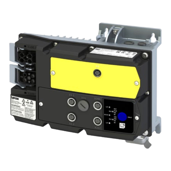
Han Q4/2 female (Daisy Chain) Fan, option Warnings Status LEDs X3.1 Control connections X105 Motor connection X3.2 Control connections Diagnostic interface Han Q8 M23 power Network (OUT) X397 X396 Network (IN) © 03/2022 · EN · www.Lenze.com... - Page 3 The complete documentation, further • The cables must be installed in accordance with EN IEC 60204-1 or US National Electrical information and tools regarding Lenze products can be found on the Internet: Code NFPA 70/Canadian Electrical Code C22.1.
-
Page 4: Identification Of The Products
With repair switch with protective func- Motor adapter for BG160 - BG180 tion, monitored, control element, and potentiometer Application area Default parameter setting: Region EU (50- Hz networks) Default parameter setting: Region US (60- Hz networks) © 03/2022 · EN · www.Lenze.com... - Page 5 Indicates an extremely hazardous situation. If this instruction is ignored, serious, irreversible injury or deadly injuries may result. NOTE Indicates a material hazard. If this instruction is ignored, damage to property may result. © 03/2022 · EN · www.Lenze.com...
-
Page 6: Safety Instructions
- They are familiar with installing, mounting, commissioning, and operating the product. - They have the corresponding qualifications for their work. - They know and can apply all regulations for the prevention of accidents, directives, and laws applicable at the place of use. © 03/2022 · EN · www.Lenze.com... - Page 7 In the event of a short circuit of two power transistors, a residual movement of up to 180°/ number of pole pairs on the motor may occur (e.g. 4-pole motor): Residual movement max. 180 °/2 = 90°). © 03/2022 · EN · www.Lenze.com...
-
Page 8: Technical Data
Device-specific; see technical data in project planning document Max. output frequency 0 Hz ... 599 Hz Overload capacity 200 % for 3s, 150 % for 60s Further standards and operating conditions can be found in the project planning documents. © 03/2022 · EN · www.Lenze.com... -
Page 9: Mechanical Installation
I55AMxxxC 1.5 ... 3 kW 4x M5 >50 3-phase mains connection 400/480 V devices I55AMxxxF 0.37 ... 2.2 kW 4x M5 >50 I55AMxxxF 3 ... 5.5 kW 4x M5 >50 © 03/2022 · EN · www.Lenze.com... -
Page 10: Electrical Installation
• Device screws must be tightened to the specified tightening torque. NOTE For voltage supply with DC 24 ... 48 V (-20 % ... +4 %), use only a safely separated power supply unit in accordance with prevailing SELV/PELV requirements. © 03/2022 · EN · www.Lenze.com... -
Page 11: Connection Diagram
Several inverters in close proximity can be connected to the mains using the integrated n.c. Han-Q4/2 connectors. The mains cables are looped through from one inverter to the next via X3.2 the Han-Q4/2 connector. 24V| L+(2) GND| L-(2) DI3| DO2|C/Q(2) n.c. " " © 03/2022 · EN · www.Lenze.com... - Page 12 Max. rated current Max. short-circuit current (SCCR) Circuit breaker Characteristic Max. rated current Max. short-circuit current (SCCR) Residual current device (RCD) ≥ 30 mA, type B * Overload time = 3 s, recovery time = 12 s © 03/2022 · EN · www.Lenze.com...
- Page 13 Max. rated current Max. short-circuit current (SCCR) Circuit breaker Characteristic Max. rated current Max. short-circuit current (SCCR) Residual current device (RCD) ≥ 30 mA, type B * Overload time = 3 s, recovery time = 12 s © 03/2022 · EN · www.Lenze.com...
- Page 14 Max. rated current Max. short-circuit current (SCCR) Circuit breaker Characteristic Max. rated current Max. short-circuit current (SCCR) Residual current device (RCD) ≥ 30 mA, type B * Overload time = 3 s, recovery time = 12 s © 03/2022 · EN · www.Lenze.com...
-
Page 15: Control Connections
M12 (A coded) X3.1 X3.2 24 V 24 V Not assigned Housing is connected to functional earth Further configuration options for the connectors can be found in the commissioning document. © 03/2022 · EN · www.Lenze.com... -
Page 16: Ptc Input
M12 connectors as well as to the auxiliary supply to not restrict the safe isolation of the M12 connectors. © 03/2022 · EN · www.Lenze.com... - Page 17 • Modbus TCP • PROFINET The Ethernet interface is designed as an M12 connector: X396 (IN) / X397 (OUT) M12 (D coded) Assignment Housing is connected to functional earth © 03/2022 · EN · www.Lenze.com...
-
Page 18: Functional Safety
• For safety-related braking functions, use safety-rated brakes only. • The user must ensure that the inverter is only operated within the specified environmental conditions in its intended application. Only by doing so can the specified safety-related characteristics be adhered to. © 03/2022 · EN · www.Lenze.com... - Page 19 S2: Safety switching device Switch-off time Safety-related characteristic values and further example circuits can be found in the project Input current SIA planning document. Input current SIB Input peak current Test pulse duration Test pulse interval © 03/2022 · EN · www.Lenze.com...
-
Page 20: Initial Switch-On
• The control connections of the safety technology must be wired. 1. Switch on mains voltage. 2. Check readiness for operation. 3. Observe the "DRIVE" LED status display on the front of the inverter. © 03/2022 · EN · www.Lenze.com... -
Page 21: Important Notes
• Parameterizing without motor operation does not require a mains voltage. If you connect the inverter directly to the PC without a hub, the USB interface of the PC is sufficient for the voltage supply. © 03/2022 · EN · www.Lenze.com... - Page 22 »EASY Starter« searches for connected devices via the communication path selected. When the connection has been established successfully, the inverter is displayed in the device list of »EASY Starter«. The inverter parameters can now be accessed via the tabs of »EASY Starter«. © 03/2022 · EN · www.Lenze.com...
-
Page 23: Quick Commissioning
Start drive: • Drive enabled: X1/SIA = HIGH and X1/SIB = HIGH • Start drive: X3.1/DI1 = HIGH - The drive rotates with setpoint frequency preset 1 (0x2911:001) Stop drive again: X3.1/DI1 = LOW © 03/2022 · EN · www.Lenze.com... -
Page 24: Parameter List
Group 0 - favorites Group 0 contains the configurable favorites that are also contained in the groups 1 to 4. In the default setting these are the most common parameters for the solution of typical applications. © 03/2022 · EN · www.Lenze.com... - Page 25 • The V/f base voltage is usually set to the rated motor voltage. • The V/f base frequency is usually set to the rated motor frequency. 0x2B01:002 Base frequency 0 ... 50 ... 1500 Hz * Default setting dependent on the model © 03/2022 · EN · www.Lenze.com...
- Page 26 Start reverse Not connected Trigger = TRUE > FALSE (edge): No action. To stop the motor, set function "Start" to FALSE (0x2631:002, default digital input 1). * Default setting dependent on the model © 03/2022 · EN · www.Lenze.com...
- Page 27 Parameterizable frequency setpoints Setpoint frequency 0x2911:003 0.0 ... 50.0 ... 599.0 Hz presets: Preset value 3 Setpoint frequency 0x2911:004 0.0 ... 0.0 ... 599.0 Hz presets: Preset value 4 * Default setting dependent on the model © 03/2022 · EN · www.Lenze.com...
- Page 28 (0x2916) to standstill. In the case of a lower actual frequency, the actual deceleration time is reduced accordingly. • Setting is not effective in the operating mode 0x6060 = “CiA: Velocity mode [2]”. © 03/2022 · EN · www.Lenze.com...
-
Page 29: Group 3 - Motor Control
Motor parameter: Rated voltage 0 ... 230 ... 65535 V Only enter the data applying to the connection type selected. 0x2C01:008 Motor parameter: Cosine phi 0.00 ... 0.80 ... 1.00 © 03/2022 · EN · www.Lenze.com... - Page 30 On / start successfully, the value 0 is shown. 0x2022:002 Device commands: Save user data • Do not switch off the supply voltage during the saving process! Off/ready Only status feedback © 03/2022 · EN · www.Lenze.com...
-
Page 31: Troubleshooting
2. Via error reset signal (0x2631:004, default digital input 2). • Prerequisite: Cause of error has been eliminated and no blocking time is active. • The error is reset if a signal is applied to digital input 2. © 03/2022 · EN · www.Lenze.com... -
Page 32: Error Codes
• Check optional external auxiliary supply on X100.1/24E.1, if connected. 5112 24 V supply critical Warning • Check mains voltage. 5180 24 V supply overload Warning • Check 24 V output and digital outputs for earth fault or overload. © 03/2022 · EN · www.Lenze.com... - Page 33 Motor overspeed Error • Adapt the maximum motor speed (0x6080) and the error threshold (0x2D44:001). FF37 Automatic start disabled Error • Deactivate start command and reset error. © 03/2022 · EN · www.Lenze.com...
- Page 34 Inverter enabled, warning active. The motor rotates according to the specified setpoint or blinking fast quick stop active. Inverter enabled, quick stop active as response to a fault. blinking © 03/2022 · EN · www.Lenze.com...
- Page 35 LED status Support Support Further information can be found on the online page www.lenze.com/product-information The material number of the product can be found on the nameplate. © 03/2022 · EN · www.Lenze.com...
- Page 36 More detailed information on disposal can be obtained from the corresponding specialist firms and the competent authorities. The packaging of the component must be disposed of separately. Paper, cardboard and plastics must be recycled. © 03/2022 · EN · www.Lenze.com...
Need help?
Do you have a question about the i550 Series and is the answer not in the manual?
Questions and answers