Lenze i550 Mounting And Switch-On Instructions
Protec frequency inverter ip31, ip66 / nema 1, nema 4x outdoor
Hide thumbs
Also See for i550:
- Commissioning manual (704 pages) ,
- Project planning manual (264 pages) ,
- Mounting and switch-on instructions (212 pages)
Table of Contents
Advertisement
Available languages
Available languages
Montage- und Einschaltanleitung | Mounting and switch-on instructions
Umrichter
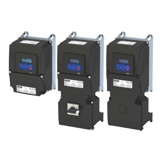
Frequenzumrichter i550 protec IP31, IP66 / NEMA 1, NEMA 4X outdoor
0.37 kW ... 11 kW,
0.5 hp ... 15 hp
1-phasiger Netzanschluss 120 V
1-phasiger Netzanschluss 230/240 V
3-phasiger Netzanschluss 230/240 V
3-phasiger Netzanschluss 400 V
3-phasiger Netzanschluss 480 V
3-phasiger Netzanschluss 600 V
Inverter
i550 protec frequency inverter IP31, IP66 / NEMA 1, NEMA 4X outdoor
0.37 kW ... 11 kW,
0.5 hp ... 15 hp
Single-phase mains connection 120 V
Single-phase mains connection 230/240 V
Three-phase mains connection 230/240 V
Three-phase mains connection 400 V
Three-phase mains connection 480 V
Three-phase mains connection 600 V
Advertisement
Chapters
Table of Contents

Related Manuals for Lenze i550


Summary of Contents for Lenze i550
- Page 1 3-phasiger Netzanschluss 400 V 3-phasiger Netzanschluss 480 V 3-phasiger Netzanschluss 600 V Inverter i550 protec frequency inverter IP31, IP66 / NEMA 1, NEMA 4X outdoor 0.37 kW ... 11 kW, 0.5 hp ... 15 hp Single-phase mains connection 120 V...
- Page 3 Montage- und Einschaltanleitung | Mounting and switch-on instructions DE - Frequenzumrichter i550 protec IP31, IP66 / NEMA 1, NEMA 4X outdoor EN - i550 protec frequency inverter IP31, IP66 / NEMA 1, NEMA 4X outdoor...
-
Page 5: Table Of Contents
Inhalt Inhalt Über dieses Dokument Weiterführende Dokumente Schreibweisen und Konventionen Sicherheitshinweise Grundlegende Sicherheitshinweise Bestimmungsgemäße Verwendung Vorhersehbarer Fehlgebrauch Restgefahren Produktinformation Identifizierung der Produkte Ausstattung Lizenzinformation Mechanische Installation Abmessungen... - Page 6 Inhalt Elektrische Installation Wichtige Hinweise EMV-gerechte Installation Anschluss nach UL Wichtige Hinweise Absicherungsdaten Branch Circuit Protection (BCP)
- Page 7 Inhalt Netzanschluss 1-phasiger Netzanschluss 120 V Anschlusspläne Klemmendaten Absicherungsdaten 1-phasiger Netzanschluss 230/240 V Anschlusspläne Klemmendaten Absicherungsdaten 1-phasiger Netzanschluss 230/240 V "Light Duty" Anschlusspläne Klemmendaten Absicherungsdaten 3-phasiger Netzanschluss 230/240 V Anschlusspläne Klemmendaten Absicherungsdaten 3-phasiger Netzanschluss 230/240 V "Light Duty" Anschlusspläne Klemmendaten Absicherungsdaten 3-phasiger Netzanschluss 400 V Anschlusspläne...
- Page 8 Inhalt Anschluss Bremswiderstand Steueranschlüsse Netzwerke CANopen EtherCAT EtherNet/IP Modbus RTU Modbus TCP PROFINET IO-Link Funktionale Sicherheit Basic Safety - STO Anschlussplan Klemmendaten Inbetriebnahme Wichtige Hinweise Erstes Einschalten und Funktionstest Zubehör verwenden Keypad Keypad-Bedienmodus Funktion der Keypad-Tasten im Bedienmodus Keypad-Parametriermodus Funktion der Keypad-Tasten im Parametriermodus Diagnose und Störungsbeseitigung LED-Statusanzeigen...
- Page 9 Inhalt Technische Daten Normen und Einsatzbedingungen Konformitäten und Approbationen Personenschutz und Geräteschutz Angaben zur EMV Motoranschluss Umweltbedingungen Netzbedingungen 1-phasiger Netzanschluss 120 V Bemessungsdaten 1-phasiger Netzanschluss 230/240 V Bemessungsdaten 1-phasiger Netzanschluss 230/240 V "Light Duty" Bemessungsdaten 3-phasiger Netzanschluss 230/240 V Bemessungsdaten 3-phasiger Netzanschluss 230/240 V "Light Duty"...
-
Page 10: Über Dieses Dokument
CAD-Daten Download in verschiedenen Formaten aus dem EASY Product Finder EPLAN-Makros Projektierung, Dokumentation und Verwaltung von Projekten für EPLAN P8. Diese Medien finden Sie hier: Lenze.com Informationen und Hilfsmittel rund um die Lenze-Produkte finden Sie im Internet: www.Lenze.com à Downloads... -
Page 11: Schreibweisen Und Konventionen
Über dieses Dokument Schreibweisen und Konventionen Schreibweisen und Konventionen Zur Unterscheidung verschiedener Arten von Informationen werden in diesem Dokument Konventionen ver- wendet. Zahlenschreibweise Dezimaltrennzeichen Punkt Werden generell als Dezimalpunkt dargestellt. Beispiel: 1 234.56 Warnhinweise UL-Warnhinweise Werden in englischer und französischer Sprache verwendet. UR-Warnhinweise Textauszeichnung Engineering Tools... -
Page 12: Sicherheitshinweise
Sicherheitshinweise Grundlegende Sicherheitshinweise Sicherheitshinweise Wenn Sie die folgenden grundlegenden Sicherheitsmaßnahmen und Sicherheitshinweise missachten, kann dies zu schweren Personenschäden und Sachschäden führen! Beachten Sie die Vorgaben der beiliegenden und zugehörigen Dokumentation. Dies ist Voraussetzung für einen sicheren und störungsfreien Betrieb, sowie für das Erreichen der angegebenen Produkteigenschaften. Beachten Sie die spezifischen Sicherheitshinweise in den anderen Abschnitten! Grundlegende Sicherheitshinweise GEFAHR! -
Page 13: Bestimmungsgemäße Verwendung
Sicherheitshinweise Vorhersehbarer Fehlgebrauch Bestimmungsgemäße Verwendung • Das Produkt dient als Komponente der Ansteuerung von Drehstrommotoren und Servomotoren. • Das Produkt darf nur mit Motoren betrieben werden, die für den Betrieb mit Umrichtern geeignet sind. • Das Produkt ist kein Haushaltsgerät, sondern ein elektrisches Betriebsmittel ausschließlich bestimmt für die Weiterverwendung zur gewerblichen Nutzung bzw. -
Page 14: Restgefahren
Sicherheitshinweise Restgefahren Restgefahren Auch wenn gegebene Hinweise beachtet und Schutzmaßnahmen angewendet werden, können Restrisiken verbleiben. Die genannten Restgefahren muss der Anwender in der Risikobeurteilung für seine Maschine/Anlage berück- sichtigen. Nichtbeachtung kann zu schweren Personenschäden und Sachschäden führen! Produkt Beachten Sie die Warnschilder auf dem Produkt und deren Bedeutung! GEFAHR! Lebensgefahr durch elektrische Spannung! Die Leistungsanschlüsse des Produktes können nach Netzabschaltung noch spannungsführend sein. - Page 15 Sicherheitshinweise Restgefahren Motor Bei Kurzschluss zweier Leistungstransistoren kann am Motor eine Restbewegung von bis zu 180°/Polpaarzahl auftreten! (Z. B. 4-poliger Motor: Restbewegung max. 180°/2 = 90°).
-
Page 16: Produktinformation
In Tabellen werden die ersten 9 Stellen des jeweiligen Produktcodes verwendet, um die Produkte zu identifi- zieren: Produktcode I 5 5 A P □□□ □ □ □ □ □ □ □ □□□ Produktart Umrichter Produktfamilie i500 Produkt i550 Produktgeneration Generation 1 Montageart Wandmontage Bemessungsleistung [kW] 0.25 kW (Beispiele) 0.55 kW 2.2 kW... -
Page 17: Ausstattung
Produktinformation Ausstattung Ausstattung 0.37 kW ... 11 kW Status LEDs Netzwerk Speichermodul X2xx Netzwerk, Option EtherCAT, PROFINET, EtherNet/IP, Modbus TCP X109 PTC-Eingang Drehcodierschalter Bedienmodul Keypad oder WLAN-Modul IP-S chalter Steuerklemmen Standard I/O X2xx Netzwerk, Option CANopen, Modbus RTU, IO-Link Status LEDs Umrichter Relaisausgang Diagnoseschnittstelle... -
Page 18: Lizenzinformation
Produktinformation Lizenzinformation Lizenzinformation PROFINET Die PROFINET-Firmware ist optional. Die PROFINET-Firmware nutzt folgende Open-Source-Softwarepakete unter modifizierter GPL- Lizenz: eCos Operating System. Diese Komponenten werden auf der Betriebssystemebene der Firm- ware verwendet. Der Protokollstack verwendet keinen Sourcecode unter GPL-Lizenz. Lizenz einsehen... -
Page 19: Mechanische Installation
Mechanische Installation Mechanische Installation Abmessungen Die angegebenen Einbaufreiräume sind Mindestmaße, um die ausreichende Luftzirkulation für die Kühlung zu gewährleisten. Sie berücksichtigen nicht die Biegeradien der Anschlussleitungen. 0.37 kW ... 0.75 kW Die Abmessungen in mm gelten für: 0.37 kW I55AP137A I55AP137B I55AP137D I55AP137F... - Page 20 Mechanische Installation Abmessungen 0.5 hp ... 1 hp Die Abmessungen in inch gelten für: 0.5 hp I55AP137A I55AP137B I55AP137D I55AP137F 0.75 hp I55AP155B I55AP155D I55AP155F 1 hp I55AP175B I55AP175D I55AP175F I55AP175G...
- Page 21 Mechanische Installation Abmessungen 0.75 kW ... 2.2 kW Die Abmessungen in mm gelten für: 0.75 kW I55AP175A 1.1 kW I55AP211A I55AP211B I55AP211D I55AP211F 1.5 kW I55AP215B I55AP215D I55AP215F I55AP215G 2.2 kW I55AP222B I55AP222D I55AP222F I55AP222G...
- Page 22 Mechanische Installation Abmessungen 1.5 hp ... 3 hp Die Abmessungen in inch gelten für: 1 hp I55AP175A 1.5 hp I55AP211A I55AP211B I55AP211D I55AP211F 2 hp I55AP215B I55AP215D I55AP215F I55AP215G 3 hp I55AP222B I55AP222D I55AP222F I55AP222G...
- Page 23 Mechanische Installation Abmessungen 3 kW ... 5.5 kW Die Abmessungen in mm gelten für: 3 kW I55AP230C I55AP230F 4 kW I55AP240C I55AP240F 5.5 kW I55AP255C I55AP255F...
- Page 24 Mechanische Installation Abmessungen 4 hp ... 7.5 hp Die Abmessungen in inch gelten für: 4 hp I55AP230C I55AP230F 5 hp I55AP240C I55AP240F 7.5 hp I55AP255C I55AP255F...
- Page 25 Mechanische Installation Abmessungen 7.5 kW ... 11 kW Die Abmessungen in mm gelten für: 7.5 kW I55AP275C I55AP275F 11 kW I55AP311C I55AP311F...
- Page 26 Mechanische Installation Abmessungen 10 hp ... 15 hp Die Abmessungen in inch gelten für: 10 hp I55AP275C I55AP275F 15 hp I55AP311C I55AP311F...
- Page 27 Mechanische Installation Abmessungen Abmessungen für Geräte mit Extension Box I55APxxxx1xxxxxxxx - Extension Box leer I55APxxxx2xxxxxxxx - Extension Box mit Reparaturschalter 0.37 kW ... 0.75 kW Die Abmessungen in mm gelten für: 0.37 kW I55AP137A I55AP137B I55AP137D I55AP137F 0.55 kW I55AP155B I55AP155D I55AP155F 0.75 kW...
- Page 28 Mechanische Installation Abmessungen 0.5 hp ... 1 hp Die Abmessungen in inch gelten für: 0.5 hp I55AP137A I55AP137B I55AP137D I55AP137F 0.75 hp I55AP155B I55AP155D I55AP155F 1 hp I55AP175B I55AP175D I55AP175F I55AP175G...
- Page 29 Mechanische Installation Abmessungen 0.75 kW ... 2.2 kW Die Abmessungen in mm gelten für: 0.75 kW I55AP175A 1.1 kW I55AP211A I55AP211B I55AP211D I55AP211F 1.5 kW I55AP215B I55AP215D I55AP215F I55AP215G 2.2 kW I55AP222B I55AP222D I55AP222F I55AP222G...
- Page 30 Mechanische Installation Abmessungen 1.5 hp ... 3 hp Die Abmessungen in inch gelten für: 1 hp I55AP175A 1.5 hp I55AP211A I55AP211B I55AP211D I55AP211F 2 hp I55AP215B I55AP215D I55AP215F I55AP215G 3 hp I55AP222B I55AP222D I55AP222F I55AP222G...
- Page 31 Mechanische Installation Abmessungen 3 kW ... 5.5 kW Die Abmessungen in mm gelten für: 3 kW I55AP230C I55AP230F 4 kW I55AP240C I55AP240F 5.5 kW I55AP255C I55AP255F...
- Page 32 Mechanische Installation Abmessungen 4 hp ... 7.5 hp Die Abmessungen in inch gelten für: 4 hp I55AP230C I55AP230F 5 hp I55AP240C I55AP240F 7.5 hp I55AP255C I55AP255F...
- Page 33 Mechanische Installation Abmessungen 7.5 kW ... 11 kW Die Abmessungen in mm gelten für: 7.5 kW I55AP275C I55AP275F 11 kW I55AP311C I55AP311F...
- Page 34 Mechanische Installation Abmessungen 10 hp ... 15 hp Die Abmessungen in inch gelten für: 10 hp I55AP275C I55AP275F 15 hp I55AP311C I55AP311F...
-
Page 35: Elektrische Installation
Elektrische Installation Elektrische Installation Wichtige Hinweise GEFAHR! Elektrische Spannung Mögliche Folge: Tod oder schwere Verletzungen ▶ Alle Arbeiten am Umrichter nur im spannungslosen Zustand durchführen. ▶ Umrichter bis 45 kW: Nach dem Abschalten der Netzspannung mindestens 3 min warten, bevor Sie mit den Arbeiten beginnen. - Page 36 Elektrische Installation Wichtige Hinweise Deckelverschraubung öffnen und schließen Für die Verdrahtung die 4 Schrauben im Deckel mit einem Kreuzschlitzschraubendreher lösen. Nach Fertigstellung den Deckel mit den 4 Schrauben wieder verschließen, damit die Schutzart gewährleis- tet bleibt. 1.2 Nm (10.6 lb-in) Kabelverschraubungen Immer Kabelverschraubungen mit langem Gewinde verwenden.
-
Page 37: Emv-Gerechte Installation
Elektrische Installation EMV-gerechte Installation EMV-gerechte Installation Das Antriebssystem aus Umrichter und Antrieb entspricht der EMV-Richtlinie 2014/30/EU nur, wenn es nach den Vorgaben des CE-typischen Antriebssystems installiert wird. Diese Richtlinien sollten auch bei Installationen nach FCC Part 15 oder ICES 001 beachtet werden. HINWEIS Elektromagnetische Störungen Produkt und Peripheriegeräte können im Betrieb beeinträchtigt werden. -
Page 38: Anschluss Nach Ul
Elektrische Installation Anschluss nach UL Wichtige Hinweise Anschluss nach UL Wichtige Hinweise WARNUNG! ▶ UL marking ▶ The integral solid state short circuit protection included in the inverter does not provide branch circuit protection. Branch circuit protection must be provided in accordance with the National Electrical Code / Canadian Electrical Code and any additional local codes. -
Page 39: Absicherungsdaten
Elektrische Installation Anschluss nach UL Absicherungsdaten HINWEIS ▶ UL marking ▶ Internal overload protection rated for 125 % of the rated FLA. ▶ Marquage UL ▶ Protection contre les surcharges conçue pour se déclencher à 125 % de l'intensité assignée à pleine charge. -
Page 40: Netzanschluss
Elektrische Installation Netzanschluss Netzanschluss Der Anschlussplan gilt beispielhaft für alle Spannungsklassen und Leistungsklassen. Abweichende Netzan- schlusspläne befinden sich in den dazugehörigen Kapiteln. 3/N/ PE AC 400 V … 3/ PE 340 V ... 528 V 45 Hz ... 65 Hz CANopen Modbus RTU EtherCAT... -
Page 41: 1-Phasiger Netzanschluss 120 V
Elektrische Installation Netzanschluss 1-phasiger Netzanschluss 120 V 1-phasiger Netzanschluss 120 V Anschlusspläne Der Anschlussplan ist gültig für die Umrichter I55APxxxA. Umrichter I55APxxxA haben kein integriertes Funkentstörfilter in der AC-Netzeinspeisung. Um die EMV-Anforderungen nach EN 61800−3 zu erfüllen, muss ein externes EMV-Filter nach IEC EN 60939 eingesetzt werden. -
Page 42: Klemmendaten
Elektrische Installation Netzanschluss 1-phasiger Netzanschluss 120 V Klemmendaten Bemessungsleistung 0.37 ... 0.37 0.75 ... 1.1 Beschreibung des Anschlus- Netzanschluss Anschluss X100 Anschlusstyp Nicht steckbar Max. Leitungsquerschnitt mm² Max. Leitungsquerschnitt Abisolierlänge Abisolierlänge Anzugsdrehmoment Anzugsdrehmoment lb-in Benötigtes Werkzeug 1.2 x 8.0 0.6 x 3.5 Bemessungsleistung 0.37 ... -
Page 43: 1-Phasiger Netzanschluss 230/240 V
Elektrische Installation Netzanschluss 1-phasiger Netzanschluss 230/240 V 1-phasiger Netzanschluss 230/240 V Anschlusspläne Der Anschlussplan ist gültig für die Umrichter I55APxxxB und I55APxxxD. Umrichter I55APxxxD haben kein integriertes Funkentstörfilter in der AC-Netzeinspeisung. Um die EMV-Anforderungen nach EN 61800−3 zu erfüllen, muss ein externes EMV-Filter nach IEC EN 60939 eingesetzt werden. -
Page 44: Klemmendaten
Elektrische Installation Netzanschluss 1-phasiger Netzanschluss 230/240 V Klemmendaten Bemessungsleistung 0.37 ... 2.2 Beschreibung des Anschlus- Netzanschluss Anschluss X100 Anschlusstyp Nicht steckbar Max. Leitungsquerschnitt mm² Max. Leitungsquerschnitt Abisolierlänge Abisolierlänge Anzugsdrehmoment Anzugsdrehmoment lb-in Benötigtes Werkzeug 1.2 x 8.0 Bemessungsleistung 0.37 ... 2.2 Beschreibung des Anschlus- PE-Anschluss Anschluss... -
Page 45: Absicherungsdaten
Elektrische Installation Netzanschluss 1-phasiger Netzanschluss 230/240 V "Light Duty" Absicherungsdaten Eine Fehlerstrom-Schutzeinrichtung (RCD) ist optional. Absicherungsdaten für UL/NEC-konforme Installationen: 4Absicherungsdaten ^ 39 Umrichter Schmelzsicherung Sicherungsautomat Max. Bemes- Max. Bemes- Charakteristik Charakteristik sungsstrom sungsstrom I55AP137B..7 gG/gL, gRL ≥30 Typ B I55AP137D..3 gG/gL, gRL ≥30 Typ B... -
Page 46: 3-Phasiger Netzanschluss 230/240 V
Elektrische Installation Netzanschluss 3-phasiger Netzanschluss 230/240 V 3-phasiger Netzanschluss 230/240 V Anschlusspläne Der Anschlussplan ist gültig für die Umrichter I55APxxxC und I55APxxxD. Umrichter I55APxxxC und I55APxxxD haben kein integriertes Funkentstörfilter in der AC-Netzein- speisung. Um die EMV-Anforderungen nach EN 61800−3 zu erfüllen, muss ein externes EMV-Filter nach IEC EN 60939 eingesetzt werden. -
Page 47: Klemmendaten
Elektrische Installation Netzanschluss 3-phasiger Netzanschluss 230/240 V Klemmendaten Bemessungsleistung 0.37 ... 0.75 1.1 ... 5.5 7.5 ... 11 Beschreibung des Anschlus- Netzanschluss Anschluss X100 Anschlusstyp Nicht steckbar Max. Leitungsquerschnitt mm² Max. Leitungsquerschnitt Abisolierlänge Abisolierlänge 0.35 0.43 Anzugsdrehmoment Anzugsdrehmoment lb-in Benötigtes Werkzeug 1.2 x 8.0 0.6 x 3.5 0.8 x 4.0... -
Page 48: Absicherungsdaten
Elektrische Installation Netzanschluss 3-phasiger Netzanschluss 230/240 V "Light Duty" Absicherungsdaten Eine Fehlerstrom-Schutzeinrichtung (RCD) ist optional. Absicherungsdaten für UL/NEC-konforme Installationen: 4Absicherungsdaten ^ 39 Umrichter Schmelzsicherung Sicherungsautomat Max. Bemes- Max. Bemes- Charakteristik Charakteristik sungsstrom sungsstrom I55AP137D..3 gG/gL, gRL ≥30 Typ B I55AP137D..7 gG/gL, gRL ≥30 Typ B... -
Page 49: Anschlusspläne
Elektrische Installation Netzanschluss 3-phasiger Netzanschluss 400 V 3-phasiger Netzanschluss 400 V Anschlusspläne Der Anschlussplan ist gültig für die Umrichter I55APxxxF. 3/N/PE AC 400 V … 3/PE AC 340 V ... 528 V 45 Hz ... 65 Hz... -
Page 50: Klemmendaten
Elektrische Installation Netzanschluss 3-phasiger Netzanschluss 400 V Klemmendaten Bemessungsleistung 0.37 ... 5.5 7.5 ... 11 Beschreibung des Anschlus- Netzanschluss Anschluss X100 Anschlusstyp Nicht steckbar Max. Leitungsquerschnitt mm² Max. Leitungsquerschnitt Abisolierlänge Abisolierlänge 0.43 Anzugsdrehmoment Anzugsdrehmoment lb-in Benötigtes Werkzeug 1.2 x 8.0 0.8 x 4.0 Bemessungsleistung 0.37 ... -
Page 51: Absicherungsdaten
Elektrische Installation Netzanschluss 3-phasiger Netzanschluss 400 V Absicherungsdaten Eine Fehlerstrom-Schutzeinrichtung (RCD) ist optional. Absicherungsdaten für UL/NEC-konforme Installationen: 4Absicherungsdaten ^ 39 Umrichter Schmelzsicherung Sicherungsautomat Max. Bemes- Max. Bemes- Charakteristik Charakteristik sungsstrom sungsstrom I55AP137F..3 gG/gL, gRL ≥30 Typ B I55AP137F..7 gG/gL, gRL ≥30 Typ B I55AP155F..3... -
Page 52: 3-Phasiger Netzanschluss 400 V
Elektrische Installation Netzanschluss 3-phasiger Netzanschluss 400 V "Light Duty" 3-phasiger Netzanschluss 400 V "Light Duty" Anschlusspläne 4Anschlusspläne ^ 49 Klemmendaten 4Klemmendaten ^ 50 Absicherungsdaten Eine Fehlerstrom-Schutzeinrichtung (RCD) ist optional. Absicherungsdaten für UL/NEC-konforme Installationen: 4Absicherungsdaten ^ 39 Umrichter Schmelzsicherung Sicherungsautomat Max. Bemes- Max. -
Page 53: Anschlusspläne
Elektrische Installation Netzanschluss 3-phasiger Netzanschluss 480 V 3-phasiger Netzanschluss 480 V Anschlusspläne Der Anschlussplan ist gültig für die Umrichter I55APxxxF und I55APxxxG . Umrichter I55APxxxG haben kein integriertes Funkentstörfilter in der AC-Netzeinspeisung. Um die EMV-Anforderungen nach EN 61800−3 zu erfüllen, muss ein externes EMV-Filter nach IEC EN 60939 eingesetzt werden. -
Page 54: Klemmendaten
Elektrische Installation Netzanschluss 3-phasiger Netzanschluss 480 V Klemmendaten Bemessungsleistung 0.37 ... 5.5 7.5 ... 11 Beschreibung des Anschlus- Netzanschluss Anschluss X100 Anschlusstyp Nicht steckbar Max. Leitungsquerschnitt mm² Max. Leitungsquerschnitt Abisolierlänge Abisolierlänge 0.43 Anzugsdrehmoment Anzugsdrehmoment lb-in Benötigtes Werkzeug 1.2 x 8.0 0.8 x 4.0 Bemessungsleistung 0.37 ... -
Page 55: Absicherungsdaten
Elektrische Installation Netzanschluss 3-phasiger Netzanschluss 480 V Absicherungsdaten Eine Fehlerstrom-Schutzeinrichtung (RCD) ist optional. Absicherungsdaten für UL/NEC-konforme Installationen: 4Absicherungsdaten ^ 39 Umrichter Schmelzsicherung Sicherungsautomat Max. Bemes- Max. Bemes- Charakteristik Charakteristik sungsstrom sungsstrom I55AP137F..3 gG/gL, gRL ≥30 Typ B I55AP137F..7 gG/gL, gRL ≥30 Typ B I55AP155F..3... -
Page 56: 3-Phasiger Netzanschluss 480 V
Elektrische Installation Netzanschluss 3-phasiger Netzanschluss 480 V "Light Duty" 3-phasiger Netzanschluss 480 V "Light Duty" Anschlusspläne 4Anschlusspläne ^ 53 Klemmendaten 4Klemmendaten ^ 54 Absicherungsdaten Eine Fehlerstrom-Schutzeinrichtung (RCD) ist optional. Absicherungsdaten für UL/NEC-konforme Installationen: 4Absicherungsdaten ^ 39 Umrichter Schmelzsicherung Sicherungsautomat Max. Bemes- Max. -
Page 57: 3-Phasiger Netzanschluss 600 V
Elektrische Installation Netzanschluss 3-phasiger Netzanschluss 600 V 3-phasiger Netzanschluss 600 V Anschlusspläne Der Anschlussplan ist gültig für die Umrichter I55APxxxG. Umrichter I55APxxxG haben kein integriertes Funkentstörfilter in der AC-Netzeinspeisung. Um die EMV-Anforderungen nach EN 61800−3 zu erfüllen, muss ein externes EMV-Filter nach IEC EN 60939 eingesetzt werden. -
Page 58: Klemmendaten
Elektrische Installation Netzanschluss 3-phasiger Netzanschluss 600 V Klemmendaten Bemessungsleistung 0.75 ... 2.2 Beschreibung des Anschlus- Netzanschluss Anschluss X100 Anschlusstyp Nicht steckbar Max. Leitungsquerschnitt mm² Max. Leitungsquerschnitt Abisolierlänge Abisolierlänge Anzugsdrehmoment Anzugsdrehmoment lb-in Benötigtes Werkzeug 1.2 x 8.0 Bemessungsleistung 0.75 ... 2.2 Beschreibung des Anschlus- PE-Anschluss Anschluss... -
Page 59: 3-Phasiger Netzanschluss 600 V "Light Duty
Elektrische Installation Motoranschluss 3-phasiger Netzanschluss 600 V "Light Duty" Anschlusspläne 4Anschlusspläne ^ 57 Klemmendaten 4Klemmendaten ^ 58 Absicherungsdaten Umrichter Schmelzsicherung Sicherungsautomat Max. Bemes- Max. Bemes- Charakteristik Charakteristik sungsstrom sungsstrom I55AP175G..3 gG/gL, gRL ≥30 Typ B I55AP215G..3 gG/gL, gRL ≥30 Typ B I55AP222G..3 gG/gL, gRL ≥30... -
Page 60: Anschluss Bremswiderstand
Elektrische Installation Anschluss Bremswiderstand Anschluss Bremswiderstand Verwenden Sie eigensichere Bremswiderstände, um auf eine getrennte Abschaltvorrichtung (z. B. ein Schütz) verzichten zu können. Kurze Anschlussleitungen bis 0.5 m Bis 0.5 m Leitungslänge können die Leitung des Bremswiderstands und die Leitung der Temperaturüberwa- chung verdrillt ausgeführt werden. - Page 61 Elektrische Installation Anschluss Bremswiderstand Lange Anschlussleitungen bis max. 5 m Die Leitung des Bremswiderstands muss geschirmt sein. Die maximale Länge beträgt 5 m. Für die Leitung der Temperaturüberwachung ist das Verdrillen ausreichend. RB1 RB2 T1 T2 " " ② ① Abb.
-
Page 62: Steueranschlüsse
Elektrische Installation Steueranschlüsse Steueranschlüsse Die Bezeichnungen der Klemmen X109, X3 und X9 befinden sich auf der Innenseite der Abdeckung. Beschreibung des Anschlus- Steuerklemmen Relaisausgang PTC-Eingang Anschluss X109 Anschlusstyp Nicht steckbar Nicht steckbar Nicht steckbar Max. Leitungsquerschnitt mm² Max. Leitungsquerschnitt Abisolierlänge Abisolierlänge 0.35 0.35... -
Page 63: Netzwerke
Elektrische Installation Netzwerke CANopen Netzwerke CANopen Das Netzwerk muss am physikalisch ersten und letzten Teilnehmer mit einem 120 Ω-Widerstand abgeschlossen sein. An diesen Netzwerkteilnehmern den DIP-Schalter "R" auf ON stellen. Typische Topologien Linie " " " " X216 X216 X216 X216 Beschreibung des Anschlus- CANopen... -
Page 64: Ethercat
Elektrische Installation Netzwerke EtherCAT EtherCAT LED "RUN" (grün) Blinkmuster Zustand Bedeutung Versorgungsspannung nicht vorhanden Initialisation (Init) Netzwerk nicht aktiv Kein Datentransfer Pre-Operational (Pre-Op) Zugriff auf Parameter und Objekte möglich Kein Prozessdatentransfer blinkt 1:1 Safe-Operational (Safe-Op) Prozesseingangsdaten (Inputs) sind gültig blitzt Operational (Op) Prozessdatentransfer mit gültigen Inputs und Outputs in Aktion LED "ERR"... - Page 65 Elektrische Installation Netzwerke EtherCAT Netzwerk-Grundeinstellungen Mit dem Drehcodierschalter können Sie den EtherCAT-Identifier einstellen. Einstellung Identifier 0x00 Wert aus Parameter 0x01 ... 0xFF Schalterstellung...
-
Page 66: Ethernet/Ip
Elektrische Installation Netzwerke EtherNet/IP EtherNet/IP Netzwerkstatus Die LEDs "NS" und "MS" zeigen den Netzwerkstatus an. LED "NS" (grün/rot) CIP-Netzwerkstatus Zustand/Bedeutung No IP adress Die Netzwerkoption wird nicht mit Spannung versorgt oder hat noch keine IP-Adresse erhalten. Connected Die Netzwerkoption arbeitet einwandfrei und hat eine Verbindung zum Scanner aufgebaut. - Page 67 Elektrische Installation Netzwerke EtherNet/IP Beschreibung des Anschlus- EtherNet/IP Anschluss X266 X267 Anschlusstyp RJ45 Netzwerk-Grundeinstellungen Mit dem Drehcodierschalter können Sie das letzte Byte der IP-Adresse einstellen. Einstellung Wert des letzten Byte Resultierende IP-Adresse 0x00 Wert aus Parameter Wert aus Parameter 0x01 ... 0xFE Schalterstellung 192.168.124.<Schalterstellung>...
-
Page 68: Modbus Rtu
Elektrische Installation Netzwerke Modbus RTU Modbus RTU Das Netzwerk muss am physikalisch ersten und letzten Teilnehmer mit einem 120 Ω-Widerstand abgeschlossen sein. An diesen Netzwerkteilnehmern den DIP-Schalter "R" auf ON stellen. Typische Topologien Linie X216 X216 X216 X216 " " "... -
Page 69: Modbus Tcp
Elektrische Installation Netzwerke Modbus TCP Modbus TCP Typische Topologien Linie Baum Master Switch Slave Busbezogene Information Bezeichnung Modbus TCP Kommunikationsmedium Ethernet 10 MBit/s, 100 MBit/s, Halb- duplex, Vollduplex Verwendung Anbindung als Modbus TCP-Slave Anschlusstechnik RJ45 Statusanzeige 2 LEDs Anschlussbezeichnung Port 1: X276 Port 2: X277 Beschreibung des Anschlus- Modbus TCP... -
Page 70: Profinet
Elektrische Installation Netzwerke PROFINET PROFINET Netzwerkstatus Die LEDs "BUS RDY" und "BUS ERR" zeigen den Netzwerkstatus an. LED "BUS RDY" (grün) Zustand Bedeutung Not connected Keine Verbindung zum IO-Controller Connected IO-Controller in STOP Blinkt Data Exchange IO-Controller in RUN (DATA_EXCHANGE) LED "BUS ERR"... -
Page 71: Io-Link
Elektrische Installation Netzwerke IO-Link IO-Link Statusanzeige Die LEDs zeigen den Verbindungsstatus zum Netzwerk an: LED "RUN" (grün) Zustand/Bedeutung Kein Datentransfer. Aktiver Datentransfer. Blinkt Typische Topologien Baum Master Device Information Bezeichnung IO-Link Spezifikation Baudrate 230.4 kbaud (COM 3) Zykluszeit 2 ms Port Class A (Typ A) I max. -
Page 72: Funktionale Sicherheit
Elektrische Installation Funktionale Sicherheit Funktionale Sicherheit GEFAHR! Bei unsachgemäßer Installation der Sicherheitstechnik können Antriebe unkontrolliert anlaufen. Mögliche Folge: Tod oder schwere Verletzungen ▶ Nur qualifiziertes Personal darf Sicherheitstechnik installieren und in Betrieb nehmen. ▶ Die komplette Verdrahtung muss EMV-gerecht ausgeführt sein. ▶... -
Page 73: Basic Safety - Sto
Elektrische Installation Funktionale Sicherheit Basic Safety - STO Basic Safety - STO GEFAHR! Mit der Funktion "Sicher abgeschaltetes Moment" (STO) ist ohne zusätzliche Maßnahmen kein "Not‑Aus" nach EN 60204−1 möglich. Zwischen Motor und Umrichter gibt es keine galvanische Trennung und keinen Serviceschalter oder Reparaturschalter! Mögliche Folge: Tod oder schwere Verletzungen ▶... -
Page 74: Klemmendaten
Elektrische Installation Funktionale Sicherheit Basic Safety - STO Klemmendaten Spezifikation Einheit min. typ. max. SIA, SIB LOW-Signal HIGH-Signal Einschaltzeit Abschaltzeit Eingangsstrom SIA Eingangsstrom SIB Eingangsspitzenstrom Testimpulsdauer Testimpulsintervall Bezugspotenzial für SIA und SIB Beschreibung des Anschlus- Basic Safety - STO Anschluss Anschlusstyp Steckbar Max. -
Page 75: Inbetriebnahme
Inbetriebnahme Wichtige Hinweise Inbetriebnahme Wichtige Hinweise GEFAHR! Fehlerhafte Verdrahtung kann zu unerwarteten Zuständen während der Inbetriebnahme führen. Mögliche Folgen: Tod, schwere Verletzungen oder Sachschäden Prüfen Sie vor dem Einschalten der Netzspannung: ▶ Die Verdrahtung auf vollständige und richtige Ausführung. ▶ Die Verdrahtung auf Kurzschlüsse und Erdschlüsse. ▶... -
Page 76: Erstes Einschalten Und Funktionstest
Erstes Einschalten und Funktionstest Zielsetzung: Den am Umrichter angeschlossenen Motor innerhalb kürzester Zeit zum Drehen bringen. Voraussetzungen: • Der angeschlossene Motor passt leistungsmäßig zum Umrichter. • Die Parametereinstellungen entsprechen dem Auslieferungszustand (Lenze-Einstellung). 1. Vorbereitung 1. Die Leistungsanschlüsse verdrahten. 4Elektrische Installation ^ 35 2. -
Page 77: Zubehör Verwenden
Zubehör verwenden Keypad-Bedienmodus Zubehör verwenden Keypad Keypad-Bedienmodus Funktion der Keypad-Tasten im Bedienmodus Im Bedienmodus kann das Keypad zur lokalen Steuerung und manuellen Sollwertvorgabe verwendet wer- den. Funktion der Keypad-Tasten im Bedienmodus Taste Betätigung Voraussetzung Aktion Kurz Lokale Keypad-Steuerung aktiv. Motor starten. Anzeige "LOC"... -
Page 78: Keypad-Parametriermodus
Zubehör verwenden Keypad Keypad-Parametriermodus Keypad-Parametriermodus Funktion der Keypad-Tasten im Parametriermodus Im Parametriermodus des Keypad können Sie sich Istwerte des Umrichters zu Diagnosezwecken anzeigen lassen und Einstellungen des Umrichters ändern. Funktion der Keypad-Tasten im Parametriermodus Taste Betätigung Voraussetzung Aktion Kurz Lokale Keypad-Steuerung aktiv. Motor starten. -
Page 79: Diagnose Und Störungsbeseitigung
Diagnose und Störungsbeseitigung LED-Statusanzeigen Diagnose und Störungsbeseitigung Diagnoseschnittstellen Der Umrichter hat eine eingebaute Micro-USB-Schnittstelle. Je nach Bestellung ist im Auslieferungszustand eines der nachfolgenden Module auf dem Umrichter aufge- steckt: • Kein Modul • Keypad • WLAN-Modul Weitere Informationen zu den Diagnosemodulen erhalten Sie hier: Download Micro-USB-Schnittstelle Die USB-Schnittstelle darf nur temporär für die Diagnose und Parametrierung des Umrichters ver- wendet werden. -
Page 80: Technische Daten
Technische Daten Angaben zur EMV Technische Daten Normen und Einsatzbedingungen Konformitäten und Approbationen Konformitäten 2014/30/EU EMV-Richtlinie (Bezug: CE-typisches Antriebssystem) 2014/35/EU Niederspannungsrichtlinie Eurasische Konformität: Elektromagnetische Verträg- TP TC 020/2011 lichkeit von technischen Erzeugnissen Eurasische Konformität: Sicherheit von Niederspan- TP TR 004/2011 nungsausrüstung Beschränkung der Verwendung bestimmter gefährli- RoHS... -
Page 81: Motoranschluss
Technische Daten Normen und Einsatzbedingungen Netzbedingungen Motoranschluss Anforderungen an die geschirmte Motorleitung < 150/300 pF/m C-Ader-Ader/C-Ader-Schirm ≥ 4 mm² / AWG 12 Kapazitätsbelag < 75/150 pF/m C-Ader-Ader/C-Ader-Schirm ≤ 2.5 mm² / AWG 14 U = Effektivwert Außenleiter zu Außenleiter Uo/U = 0.6/1.0 kV Spannungsfestigkeit Uo = Effektivwert Außenleiter zu PE U ≥... -
Page 82: 1-Phasiger Netzanschluss 120 V
Technische Daten 1-phasiger Netzanschluss 120 V Bemessungsdaten 1-phasiger Netzanschluss 120 V Bemessungsdaten Die Ausgangsströme gelten für diese Einsatzbedingungen: • Bei Schaltfrequenz 2 kHz oder 4 kHz: Umgebungstemperatur max. 45 °C (113 °F). • Bei Schaltfrequenz 8 kHz, 12 kHz oder 16 kHz: Umgebungstemperatur max. 40 °C (104 °F). Umrichter I55AP 137A... -
Page 83: 1-Phasiger Netzanschluss 230/240 V
Technische Daten 1-phasiger Netzanschluss 230/240 V Bemessungsdaten 1-phasiger Netzanschluss 230/240 V Bemessungsdaten Die Ausgangsströme gelten für diese Einsatzbedingungen: • Bei Schaltfrequenz 2 kHz oder 4 kHz: Umgebungstemperatur max. 45 °C (113 °F). • Bei Schaltfrequenz 8 kHz, 12 kHz oder 16 kHz: Umgebungstemperatur max. 40 °C (104 °F). Umrichter I55AP 137B... - Page 84 Technische Daten 1-phasiger Netzanschluss 230/240 V Bemessungsdaten Umrichter I55AP 215B 215D 222B 222D Bemessungsleistung Bemessungsleistung Netzspannungsbereich 1/PE AC 170 V ... 264 V, 45 Hz ... 65 Hz Ausgangsspannung 3 AC 0 - 230/240 V Netzbemessungsstrom ohne Netzdrossel 16.7 22.5 mit Netzdrossel Ausgangsscheinleistung Ausgangsbemessungsstrom...
-
Page 85: 1-Phasiger Netzanschluss 230/240 V "Light Duty
Technische Daten 1-phasiger Netzanschluss 230/240 V "Light Duty" Bemessungsdaten 1-phasiger Netzanschluss 230/240 V "Light Duty" Bemessungsdaten Die Ausgangsströme gelten für diese Einsatzbedingungen: • Bei Schaltfrequenz 2 kHz oder 4 kHz: Umgebungstemperatur max. 40 °C (104 °F). Umrichter I55AP 137D 155D 175D 211D 215D... -
Page 86: 3-Phasiger Netzanschluss 230/240 V
Technische Daten 3-phasiger Netzanschluss 230/240 V Bemessungsdaten 3-phasiger Netzanschluss 230/240 V Bemessungsdaten Die Ausgangsströme gelten für diese Einsatzbedingungen: • Bei Schaltfrequenz 2 kHz oder 4 kHz: Umgebungstemperatur max. 45 °C (113 °F). • Bei Schaltfrequenz 8 kHz, 12 kHz oder 16 kHz: Umgebungstemperatur max. 40 °C (104 °F). Umrichter I55AP 137D... - Page 87 Technische Daten 3-phasiger Netzanschluss 230/240 V Bemessungsdaten Umrichter I55AP 230C 240C 255C 275C 311C Bemessungsleistung Bemessungsleistung Netzspannungsbereich 3/PE AC 195 V ... 264 V, 45 Hz ... 65 Hz Ausgangsspannung 3 AC 0 - 230/240 V Netzbemessungsstrom ohne Netzdrossel 20.6 28.8 36.3 52.2...
-
Page 88: 3-Phasiger Netzanschluss 230/240 V "Light Duty
Technische Daten 3-phasiger Netzanschluss 230/240 V "Light Duty" Bemessungsdaten 3-phasiger Netzanschluss 230/240 V "Light Duty" Bemessungsdaten Die Ausgangsströme gelten für diese Einsatzbedingungen: • Bei Schaltfrequenz 2 kHz oder 4 kHz: Umgebungstemperatur max. 40 °C (104 °F). Umrichter I55AP 137D 155D 175D 211D 215D... -
Page 89: 3-Phasiger Netzanschluss 400 V
Technische Daten 3-phasiger Netzanschluss 400 V Bemessungsdaten 3-phasiger Netzanschluss 400 V Bemessungsdaten Die Ausgangsströme gelten für diese Einsatzbedingungen: • Bei Schaltfrequenz 2 kHz oder 4 kHz: Umgebungstemperatur max. 45 °C (113 °F). • Bei Schaltfrequenz 8 kHz, 12 kHz oder 16 kHz: Umgebungstemperatur max. 40 °C (104 °F). Umrichter I55AP 137F... - Page 90 Technische Daten 3-phasiger Netzanschluss 400 V Bemessungsdaten Umrichter I55AP 230F 240F 255F 275F 311F Bemessungsleistung Bemessungsleistung Netzspannungsbereich 3/PE AC 340 V ... 528 V, 45 Hz ... 65 Hz Ausgangsspannung 3 AC 0 - 400/480 V Netzbemessungsstrom ohne Netzdrossel 12.5 17.2 28.4 mit Netzdrossel...
-
Page 91: 3-Phasiger Netzanschluss 400 V "Light Duty
Technische Daten 3-phasiger Netzanschluss 400 V "Light Duty" Bemessungsdaten 3-phasiger Netzanschluss 400 V "Light Duty" Bemessungsdaten Die Ausgangsströme gelten für diese Einsatzbedingungen: • Bei Schaltfrequenz 2 kHz oder 4 kHz: Umgebungstemperatur max. 40 °C (104 °F). Umrichter I55AP 137F 155F 175F 211F 215F... -
Page 92: 3-Phasiger Netzanschluss 480 V
Technische Daten 3-phasiger Netzanschluss 480 V Bemessungsdaten 3-phasiger Netzanschluss 480 V Bemessungsdaten Die Ausgangsströme gelten für diese Einsatzbedingungen: • Bei Schaltfrequenz 2 kHz oder 4 kHz: Umgebungstemperatur max. 45 °C (113 °F). • Bei Schaltfrequenz 8 kHz, 12 kHz oder 16 kHz: Umgebungstemperatur max. 40 °C (104 °F). Umrichter I55AP 137F... - Page 93 Technische Daten 3-phasiger Netzanschluss 480 V Bemessungsdaten Umrichter I55AP 230F 240F 255F 275F 311F Bemessungsleistung Bemessungsleistung Netzspannungsbereich 3/PE AC 340 V ... 528 V, 45 Hz ... 65 Hz Ausgangsspannung 3 AC 0 - 400/480 V Netzbemessungsstrom ohne Netzdrossel 10.5 14.3 16.6 23.7...
- Page 94 Technische Daten 3-phasiger Netzanschluss 480 V Bemessungsdaten Umrichter I55AP 175G 215G 222G Bemessungsleistung 0.75 Bemessungsleistung Netzspannungsbereich 3/PE AC 340 V ... 528 V, 45 Hz ... 65 Hz Ausgangsspannung 3 AC 0 - 480/600 V Netzbemessungsstrom ohne Netzdrossel mit Netzdrossel Ausgangsscheinleistung Ausgangsbemessungsstrom 2 kHz...
-
Page 95: 3-Phasiger Netzanschluss 480 V "Light Duty
Technische Daten 3-phasiger Netzanschluss 480 V "Light Duty" Bemessungsdaten 3-phasiger Netzanschluss 480 V "Light Duty" Bemessungsdaten Die Ausgangsströme gelten für diese Einsatzbedingungen: • Bei Schaltfrequenz 2 kHz oder 4 kHz: Umgebungstemperatur max. 40 °C (104 °F). Umrichter I55AP 137F 155F 175F 211F 215F... - Page 96 Technische Daten 3-phasiger Netzanschluss 480 V "Light Duty" Bemessungsdaten Umrichter I55AP 175G 215G 222G Bemessungsleistung Bemessungsleistung Netzspannungsbereich 3/PE AC 340 V ... 528 V, 45 Hz ... 65 Hz Ausgangsspannung 3 AC 0 - 480/600 V Netzbemessungsstrom ohne Netzdrossel mit Netzdrossel Ausgangsscheinleistung Ausgangsbemessungsstrom 2 kHz...
-
Page 97: 3-Phasiger Netzanschluss 600 V
Technische Daten 3-phasiger Netzanschluss 600 V Bemessungsdaten 3-phasiger Netzanschluss 600 V Bemessungsdaten Die Ausgangsströme gelten für diese Einsatzbedingungen: • Bei Schaltfrequenz 2 kHz oder 4 kHz: Umgebungstemperatur max. 45 °C (113 °F). • Bei Schaltfrequenz 8 kHz, 12 kHz oder 16 kHz: Umgebungstemperatur max. 40 °C (104 °F). Umrichter I55AP175G I55AP215G... -
Page 98: 3-Phasiger Netzanschluss 600 V "Light Duty
Technische Daten 3-phasiger Netzanschluss 600 V "Light Duty" Bemessungsdaten 3-phasiger Netzanschluss 600 V "Light Duty" Bemessungsdaten Die Ausgangsströme gelten für diese Einsatzbedingungen: • Bei Schaltfrequenz 2 kHz oder 4 kHz: Umgebungstemperatur max. 40 °C (104 °F). Umrichter I55AP175G I55AP215G I55AP222G Bemessungsleistung Bemessungsleistung Netzspannungsbereich... -
Page 99: Umwelthinweise Und Recycling
Gegebenenfalls enthaltene Batterien/Akkus sind auf die Lebensdauer des Produkts ausgelegt und müssen vom Endnutzer weder getauscht noch anderweitig entfernt werden. Die Lenze-Produkte werden in der Regel mit Verpackungen aus Pappe oder Kunststoff verkauft. Diese Verpa- ckungen entsprechen der EU-Richtlinie 94/62/EG über Verpackungen und Verpackungsabfälle (Verpackungs- richtlinie). - Page 101 Contents Contents About this document Further documents Notations and conventions Safety instructions Basic safety instructions Application as directed Foreseeable misuse Residual hazards Product information Identification of the products Features License information Mechanical installation Dimensions...
- Page 102 Contents Electrical installation Important notes EMC-compliant installation Connection according to UL Important notes Fusing data Branch Circuit Protection (BCP)
- Page 103 Contents Mains connection 1-phase mains connection 120 V Connection diagrams Terminal data Fusing data 1-phase mains connection 230/240 V Connection diagrams Terminal data Fusing data 1-phase mains connection 230/240 V "Light Duty" Connection diagrams Terminal data Fusing data 3-phase mains connection 230/240 V Connection diagrams Terminal data Fusing data...
- Page 104 Contents Brake resistor connection Control connections Networks CANopen EtherCAT EtherNet/IP Modbus RTU Modbus TCP PROFINET IO-Link Functional safety Basic Safety - STO Connection diagram Terminal data Commissioning Important notes Initial switch-on and functional test Using accessories Keypad Keypad operating mode Function of keypad keys in operating mode Keypad parameterisation mode Function of the keypad keys in the parameterisation mode...
- Page 105 Contents Technical data Standards and operating conditions Conformities and approvals Protection of persons and device protection EMC data Motor connection Environmental conditions Electrical supply conditions 1-phase mains connection 120 V Rated data 1-phase mains connection 230/240 V Rated data 1-phase mains connection 230/240 V "Light Duty" Rated data 3-phase mains connection 230/240 V Rated data...
-
Page 106: About This Document
Download in different formats from the EASY Product Finder EPLAN macros Project planning, documentation and management of projects for EPLAN P8. These media can be found here: Lenze.com Information and tools with regard to the Lenze products can be found on the Internet: www.Lenze.com à Downloads... -
Page 107: Notations And Conventions
About this document Notations and conventions Notations and conventions Conventions are used in this document to distinguish between different types of information. Numeric notation Decimal separator Point Generally shown as a decimal point. Example: 1 234.56 Warnings UL Warnings Are used in English and French. UR warnings Text Engineering Tools... -
Page 108: Safety Instructions
The procedural notes and circuit details described are only proposals. It is up to the user to check whether they can be adapted to the particular applications. Lenze does not take any responsibility for the suitability of the procedures and circuit proposals described. -
Page 109: Application As Directed
Safety instructions Foreseeable misuse Application as directed • The product serves to control three-phase AC motors and three-phase permanent magnet AC motors (PMAC motors). • The product must only be actuated with motors that are suitable for the operation with inverters. •... -
Page 110: Residual Hazards
Safety instructions Residual hazards Residual hazards Even if notes given are taken into consideration and protective measures are implemented, the occurrence of residual risks cannot be fully prevented. The user must take the residual hazards mentioned into consideration in the risk assessment for his/her machine/system. - Page 111 Safety instructions Residual hazards Motor If there is a short circuit of two power transistors, a residual movement of up to 180°/number of pole pairs can occur at the motor! (e. g. 4-pole motor: residual movement max. 180°/2 = 90°).
-
Page 112: Product Information
In tables, the first 9 digits of the corresponding product code are used to identify the products: Product code I 5 5 A P □□□ □ □ □ □ □ □ □ □□□ Product type Inverter Product family i500 Product i550 Product generation Generation 1 Mounting type Wall mounting Rated power [kW] 0.25 kW (Examples) 0.55 kW... -
Page 113: Features
Product information Features Features 0.37 kW ... 11 kW Network status LEDs Memory module X2xx Netw rk, Option EtherCAT, PROFINET, EtherNet/IP, Modbus TCP X109 PTC input Rotary encoder switch Operating m odul Keypad or WLAN module DIP switch Control terminals Standard I/O X2xx Netw rk, Option... -
Page 114: License Information
Product information License information License information PROFINET The PROFINET firmware is optional. The PROFINET firmware uses the following open source software packages under a modified GPL license: eCos Operating System. These components are used at the operating system level of the firmware. -
Page 115: Mechanical Installation
Mechanical installation Mechanical installation Dimensions The specified installation clearances are minimum dimensions to ensure a sufficient air circulation for cooling purposes. They do not consider the bend radiuses of the connecting cables. 0.37 kW ... 0.75 kW The dimensions in mm apply to: 0.37 kW I55AP137A I55AP137B... - Page 116 Mechanical installation Dimensions 0.5 hp ... 1 hp The dimensions in inch apply to: 0.5 hp I55AP137A I55AP137B I55AP137D I55AP137F 0.75 hp I55AP155B I55AP155D I55AP155F 1 hp I55AP175B I55AP175D I55AP175F I55AP175G...
- Page 117 Mechanical installation Dimensions 0.75 kW ... 2.2 kW The dimensions in mm apply to: 0.75 kW I55AP175A 1.1 kW I55AP211A I55AP211B I55AP211D I55AP211F 1.5 kW I55AP215B I55AP215D I55AP215F I55AP215G 2.2 kW I55AP222B I55AP222D I55AP222F I55AP222G...
- Page 118 Mechanical installation Dimensions 1.5 hp ... 3 hp The dimensions in inch apply to: 1 hp I55AP175A 1.5 hp I55AP211A I55AP211B I55AP211D I55AP211F 2 hp I55AP215B I55AP215D I55AP215F I55AP215G 3 hp I55AP222B I55AP222D I55AP222F I55AP222G...
- Page 119 Mechanical installation Dimensions 3 kW ... 5.5 kW The dimensions in mm apply to: 3 kW I55AP230C I55AP230F 4 kW I55AP240C I55AP240F 5.5 kW I55AP255C I55AP255F...
- Page 120 Mechanical installation Dimensions 4 hp ... 7.5 hp The dimensions in inch apply to: 4 hp I55AP230C I55AP230F 5 hp I55AP240C I55AP240F 7.5 hp I55AP255C I55AP255F...
- Page 121 Mechanical installation Dimensions 7.5 kW ... 11 kW The dimensions in mm apply to: 7.5 kW I55AP275C I55AP275F 11 kW I55AP311C I55AP311F...
- Page 122 Mechanical installation Dimensions 10 hp ... 15 hp The dimensions in inch apply to: 10 hp I55AP275C I55AP275F 15 hp I55AP311C I55AP311F...
- Page 123 Mechanical installation Dimensions Dimensions for devices with extension box I55APxxxx1xxxxxxxx - Empty extension box I55APxxxx2xxxxxxxx - Extension box with maintenance switch 0.37 kW ... 0.75 kW The dimensions in mm apply to: 0.37 kW I55AP137A I55AP137B I55AP137D I55AP137F 0.55 kW I55AP155B I55AP155D I55AP155F...
- Page 124 Mechanical installation Dimensions 0.5 hp ... 1 hp The dimensions in inch apply to: 0.5 hp I55AP137A I55AP137B I55AP137D I55AP137F 0.75 hp I55AP155B I55AP155D I55AP155F 1 hp I55AP175B I55AP175D I55AP175F I55AP175G...
- Page 125 Mechanical installation Dimensions 0.75 kW ... 2.2 kW The dimensions in mm apply to: 0.75 kW I55AP175A 1.1 kW I55AP211A I55AP211B I55AP211D I55AP211F 1.5 kW I55AP215B I55AP215D I55AP215F I55AP215G 2.2 kW I55AP222B I55AP222D I55AP222F I55AP222G...
- Page 126 Mechanical installation Dimensions 1.5 hp ... 3 hp The dimensions in inch apply to: 1 hp I55AP175A 1.5 hp I55AP211A I55AP211B I55AP211D I55AP211F 2 hp I55AP215B I55AP215D I55AP215F I55AP215G 3 hp I55AP222B I55AP222D I55AP222F I55AP222G...
- Page 127 Mechanical installation Dimensions 3 kW ... 5.5 kW The dimensions in mm apply to: 3 kW I55AP230C I55AP230F 4 kW I55AP240C I55AP240F 5.5 kW I55AP255C I55AP255F...
- Page 128 Mechanical installation Dimensions 4 hp ... 7.5 hp The dimensions in inch apply to: 4 hp I55AP230C I55AP230F 5 hp I55AP240C I55AP240F 7.5 hp I55AP255C I55AP255F...
- Page 129 Mechanical installation Dimensions 7.5 kW ... 11 kW The dimensions in mm apply to: 7.5 kW I55AP275C I55AP275F 11 kW I55AP311C I55AP311F...
- Page 130 Mechanical installation Dimensions 10 hp ... 15 hp The dimensions in inch apply to: 10 hp I55AP275C I55AP275F 15 hp I55AP311C I55AP311F...
-
Page 131: Electrical Installation
Electrical installation Electrical installation Important notes DANGER! Electrical voltage Possible consequences: Death or severe injuries ▶ Any work on the inverter must only be carried out in the de-energized state. ▶ Inverter up to 45 kW: After switching off the mains voltage, wait for at least 3 min before you start working. - Page 132 Electrical installation Important notes Open and close screw connection of the cover For wiring purposes, loosen the 4 screws in the cover using a Phillips head screwdriver. After completing the wiring, close the cover again using the 4 screws to ensure that the degree of protection is maintained.
-
Page 133: Emc-Compliant Installation
Electrical installation EMC-compliant installation EMC-compliant installation The drive system (inverter and drive) only complies with the EMC Directive 2014/30/EU if it is installed according to the guidelines for CE-typical drive systems. These guidelines should also be followed in installations requiring FCC Part 15 or ICES 001 compliance. NOTICE Electromagnetic interferences Product and peripheral devices may be affected during operation. -
Page 134: Connection According To Ul
Electrical installation Connection according to UL Important notes Connection according to UL Important notes WARNING! ▶ UL marking ▶ The integral solid state short circuit protection included in the inverter does not provide branch circuit protection. Branch circuit protection must be provided in accordance with the National Electrical Code / Canadian Electrical Code and any additional local codes. -
Page 135: Fusing Data
Electrical installation Connection according to UL Fusing data NOTICE ▶ UL marking ▶ Internal overload protection rated for 125 % of the rated FLA. ▶ Marquage UL ▶ Protection contre les surcharges conçue pour se déclencher à 125 % de l'intensité assignée à pleine charge. -
Page 136: Mains Connection
Electrical installation Mains connection Mains connection The connection diagram is considered exemplary for all voltage and power classes. Deviating mains connection diagrams can be found in the corresponding chapters. 3/N/ PE AC 400 V … 3/ PE 340 V ... 528 V 45 Hz ... -
Page 137: 1-Phase Mains Connection 120 V
Electrical installation Mains connection 1-phase mains connection 120 V 1-phase mains connection 120 V Connection diagrams The connection plan is valid for the inverters I55APxxxA. The inverters I55APxxxA do not have an integrated RFI filter in the AC mains supply. In order to meet the EMC requirements according to EN 61800−3, an external EMC filter according to IEC EN 60939 must be used. -
Page 138: Terminal Data
Electrical installation Mains connection 1-phase mains connection 120 V Terminal data Rated power 0.37 ... 0.37 0.75 ... 1.1 rated Connection description Mains connection Connection X100 Connection type Non-pluggable Max. cable cross-section mm² Max. cable cross-section Stripping length Stripping length Tightening torque Tightening torque lb-in... -
Page 139: 1-Phase Mains Connection 230/240 V
Electrical installation Mains connection 1-phase mains connection 230/240 V 1-phase mains connection 230/240 V Connection diagrams The connection plan is valid for the inverters I55APxxxB and I55APxxxD. The inverters I55APxxxD do not have an integrated RFI filter in the AC mains supply. In order to meet the EMC requirements according to EN 61800−3, an external EMC filter according to IEC EN 60939 must be used. -
Page 140: Terminal Data
Electrical installation Mains connection 1-phase mains connection 230/240 V Terminal data Rated power 0.37 ... 2.2 rated Connection description Mains connection Connection X100 Connection type Non-pluggable Max. cable cross-section mm² Max. cable cross-section Stripping length Stripping length Tightening torque Tightening torque lb-in Required tool 1.2 x 8.0... -
Page 141: Fusing Data
Electrical installation Mains connection 1-phase mains connection 230/240 V "Light Duty" Fusing data A residual current device (RCD) is optional. Fusing data for UL/NEC compliant installations: 4Fusing data ^ 135 Inverter Fuse Circuit breaker Max. rated Max. rated Characteristic Characteristic Type current current... -
Page 142: 3-Phase Mains Connection 230/240 V
Electrical installation Mains connection 3-phase mains connection 230/240 V 3-phase mains connection 230/240 V Connection diagrams The connection plan is valid for the inverters I55APxxxC and I55APxxxD. The inverters I55APxxxC and I55APxxxD do not have an integrated RFI filter in the AC mains supply. In order to meet the EMC requirements according to EN 61800−3, an external EMC filter according to IEC EN 60939 must be used. -
Page 143: Terminal Data
Electrical installation Mains connection 3-phase mains connection 230/240 V Terminal data Rated power 0.37 ... 0.75 1.1 ... 5.5 7.5 ... 11 rated Connection description Mains connection Connection X100 Connection type Non-pluggable Max. cable cross-section mm² Max. cable cross-section Stripping length Stripping length 0.35 0.43... -
Page 144: Fusing Data
Electrical installation Mains connection 3-phase mains connection 230/240 V "Light Duty" Fusing data A residual current device (RCD) is optional. Fusing data for UL/NEC compliant installations: 4Fusing data ^ 135 Inverter Fuse Circuit breaker Max. rated Max. rated Characteristic Characteristic Type current current... -
Page 145: 3-Phase Mains Connection 400 V
Electrical installation Mains connection 3-phase mains connection 400 V 3-phase mains connection 400 V Connection diagrams The connection plan is valid for the inverters I55APxxxF. 3/N/PE AC 400 V … 3/PE AC 340 V ... 528 V 45 Hz ... 65 Hz... -
Page 146: Terminal Data
Electrical installation Mains connection 3-phase mains connection 400 V Terminal data Rated power 0.37 ... 5.5 7.5 ... 11 rated Connection description Mains connection Connection X100 Connection type Non-pluggable Max. cable cross-section mm² Max. cable cross-section Stripping length Stripping length 0.43 Tightening torque Tightening torque... -
Page 147: Fusing Data
Electrical installation Mains connection 3-phase mains connection 400 V Fusing data A residual current device (RCD) is optional. Fusing data for UL/NEC compliant installations: 4Fusing data ^ 135 Inverter Fuse Circuit breaker Max. rated Max. rated Characteristic Characteristic Type current current I55AP137F..3 gG/gL, gRL... -
Page 148: 3-Phase Mains Connection 400 V "Light Duty
Electrical installation Mains connection 3-phase mains connection 400 V "Light Duty" 3-phase mains connection 400 V "Light Duty" Connection diagrams 4Connection diagrams ^ 145 Terminal data 4Terminal data ^ 146 Fusing data A residual current device (RCD) is optional. Fusing data for UL/NEC compliant installations: 4Fusing data ^ 135 Inverter... -
Page 149: 3-Phase Mains Connection 480 V
Electrical installation Mains connection 3-phase mains connection 480 V 3-phase mains connection 480 V Connection diagrams The connection plan is valid for the inverters I55APxxxF and I55APxxxG. The inverters I55APxxxG do not have an integrated RFI filter in the AC mains supply. In order to meet the EMC requirements according to EN 61800−3, an external EMC filter according to IEC EN 60939 must be used. -
Page 150: Terminal Data
Electrical installation Mains connection 3-phase mains connection 480 V Terminal data Rated power 0.37 ... 5.5 7.5 ... 11 rated Connection description Mains connection Connection X100 Connection type Non-pluggable Max. cable cross-section mm² Max. cable cross-section Stripping length Stripping length 0.43 Tightening torque Tightening torque... -
Page 151: Fusing Data
Electrical installation Mains connection 3-phase mains connection 480 V Fusing data A residual current device (RCD) is optional. Fusing data for UL/NEC compliant installations: 4Fusing data ^ 135 Inverter Fuse Circuit breaker Max. rated Max. rated Characteristic Characteristic Type current current I55AP137F..3 gG/gL, gRL... -
Page 152: 3-Phase Mains Connection 480 V "Light Duty
Electrical installation Mains connection 3-phase mains connection 480 V "Light Duty" 3-phase mains connection 480 V "Light Duty" Connection diagrams 4Connection diagrams ^ 149 Terminal data 4Terminal data ^ 150 Fusing data A residual current device (RCD) is optional. Fusing data for UL/NEC compliant installations: 4Fusing data ^ 135 Inverter... -
Page 153: 3-Phase Mains Connection 600 V
Electrical installation Mains connection 3-phase mains connection 600 V 3-phase mains connection 600 V Connection diagrams The connection plan is valid for the inverters I55APxxxG. The inverters I55APxxxG do not have an integrated RFI filter in the AC mains supply. In order to meet the EMC requirements according to EN 61800−3, an external EMC filter according to IEC EN 60939 must be used. -
Page 154: Terminal Data
Electrical installation Mains connection 3-phase mains connection 600 V Terminal data Rated power 0.75 ... 2.2 rated Connection description Mains connection Connection X100 Connection type Non-pluggable Max. cable cross-section mm² Max. cable cross-section Stripping length Stripping length Tightening torque Tightening torque lb-in Required tool 1.2 x 8.0... -
Page 155: 3-Phase Mains Connection 600 V "Light Duty
Electrical installation Motor connection 3-phase mains connection 600 V "Light Duty" Connection diagrams 4Connection diagrams ^ 153 Terminal data 4Terminal data ^ 154 Fusing data Inverter Fuse Circuit breaker Max. rated Max. rated Characteristic Characteristic Type current current I55AP175G..3 gG/gL, gRL ≥30 Typ B I55AP215G..3... -
Page 156: Brake Resistor Connection
Electrical installation Brake resistor connection Brake resistor connection Use intrinsically safe brake resistors to be able to dispense with a separate switch-off device (e.g. a contactor). Short connecting cables up to 0.5 m Up to a cable length of 0.5 m, the cable for the brake resistor and that of the temperature monitoring can be twisted. - Page 157 Electrical installation Brake resistor connection Long connecting cables up to max. 5 m The brake resistor cable must be shielded. The maximum length is 5 m. For the temperature monitoring cable, twisting is sufficient. RB1 RB2 T1 T2 " " ②...
-
Page 158: Control Connections
Electrical installation Control connections Control connections The designations for the X109, X3 and X9 terminals can be found on the inside of the cover. Connection description Control terminals Relay output PTC input Connection X109 Connection type Non-pluggable Non-pluggable Non-pluggable Max. cable cross-section mm²... -
Page 159: Networks
Electrical installation Networks CANopen Networks CANopen The network must be terminated with a 120 Ω resistor at the first and last physical node. Set the "R" DIP switch to ON at these network nodes. Typical topologies Line " " " "... -
Page 160: Ethercat
Electrical installation Networks EtherCAT EtherCAT LED "RUN” (green) Blinking pattern Status Meaning Supply voltage not available Initialization (Init) Network not active No data transfer Pre-Operational (Pre-Op) Access to parameters and objects is possible No process data transfer Blinking 1:1 Safe-Operational (Safe-Op) Process input data (inputs) are valid Flashing Operational (Op) Process data transfer with valid inputs and outputs in action... - Page 161 Electrical installation Networks EtherCAT Basic network settings The rotary encoder switch allows you to set an EtherCAT identifier. Setting Identifier 0x00 Value from parameter 0x01 ... 0xFF Switch position...
-
Page 162: Ethernet/Ip
Electrical installation Networks EtherNet/IP EtherNet/IP Network status The "NS" and "MS" LEDs display the network status. LED "NS" (green/red) CIP network status Status/meaning No IP address The network option is not supplied with voltage or has not received an IP address yet. Connected The network option is working correctly and has established a connection to the scanner. - Page 163 Electrical installation Networks EtherNet/IP Connection description EtherNet/IP Connection X266 X267 Connection type RJ45 Basic network settings The rotary encoder switch allows you to set the last byte of the IP address. Setting Value of last byte Resulting IP address 0x00 Value from parameter Value from parameter 0x01 ...
-
Page 164: Modbus Rtu
Electrical installation Networks Modbus RTU Modbus RTU The network must be terminated with a 120 Ω resistor at the first and last physical node. Set the "R" DIP switch to ON at these network nodes. Typical topologies Line X216 X216 X216 X216 "... -
Page 165: Modbus Tcp
Electrical installation Networks Modbus TCP Modbus TCP Typical topologies Line Tree Master Switch Slave Bus-related information Name Modbus TCP Communication medium Ethernet 10 Mbps, 100 Mbps, half duplex, full duplex Connection as Modbus TCP slave Connection system RJ45 Status display 2 LEDs Connection designation Port 1: X276... -
Page 166: Profinet
Electrical installation Networks PROFINET PROFINET Network status The "BUS RDY" and "BUS ERR" LEDs display the network status. LED "BUS RDY" (green) State Meaning Not connected No connection to the IO-Controller Connected IO-Controller in STOP Blinking Data exchange IO-Controller in RUN (DATA_EXCHANGE) LED "BUS ERR"... -
Page 167: Io-Link
Electrical installation Networks IO-Link IO-Link Status display The LEDs indicate the connection status to the network: LED "RUN" (green) Status/meaning No data transfer. Active data transfer. Blinking Typical topologies Tree Master Device Information Name IO-Link Specification Baud rate 230.4 kbaud (COM 3) Cycle time 2 ms Port Class A (type A) -
Page 168: Functional Safety
Electrical installation Functional safety Functional safety DANGER! Improper installation of the safety engineering system can cause an uncontrolled starting action of the drives. Possible consequence: Death or severe injuries ▶ Safety engineering systems may only be installed and commissioned by qualified personnel. ▶... -
Page 169: Basic Safety - Sto
Electrical installation Functional safety Basic Safety - STO Basic Safety - STO DANGER! With the "Safe torque off" (STO) function, no “emergency stop" can be executed according to EN 60204−1 without additional measures. There is no electrical isolation between the motor and inverter and no service switch or maintenance switch! Possible consequences: Death or severe injuries ▶... -
Page 170: Terminal Data
Electrical installation Functional safety Basic Safety - STO Terminal data Specification Unit min. typ. max. SIA, SIB LOW signal HIGH signal Switch-on time Clear time Input current SIA Input current SIB Input peak current Test pulse duration Test pulse interval Reference potential for SIA and SIB Connection description Basic Safety - STO... -
Page 171: Commissioning
Commissioning Important notes Commissioning Important notes DANGER! Incorrect wiring can cause unexpected states during the commissioning phase. Possible consequences: death, severe injuries or damage to property Ensure the following before switching on the mains voltage: ▶ Wiring must be complete and correct. ▶... -
Page 172: Initial Switch-On And Functional Test
Target: Get the motor connected to the inverter to rotate in best time. Necessary conditions: • The power rating of the motor connected is appropriate for the inverter. • The parameter settings correspond to the delivery status (Lenze setting). 1. Preparation 1. Wire the power connections. -
Page 173: Using Accessories
Using accessories Keypad operating mode Using accessories Keypad Keypad operating mode Function of keypad keys in operating mode In the operating mode, the keypad can be used for local control and for manual setpoint selection. Function of keypad keys in operating mode Actuation Condition Action... -
Page 174: Keypad Parameterisation Mode
Using accessories Keypad Keypad parameterisation mode Keypad parameterisation mode Function of the keypad keys in the parameterisation mode In the parameterisation mode of the keypad you can have actual values of the inverter displayed for purposes of diagnostics and change settings of the inverter. Function of the keypad keys in the parameterisation mode Actuation Condition... -
Page 175: Diagnostics And Fault Elimination
Diagnostics and fault elimination LED status display Diagnostics and fault elimination Diagnostic interfaces The inverter is equipped with an on board micro USB interface. Depending on the purchase order, the inverter will include one of the following modules: • No module •... -
Page 176: Technical Data
Technical data EMC data Technical data Standards and operating conditions Conformities and approvals Conformities 2014/30/EU EMC Directive (reference: CE-typical drive system) 2014/35/EU Low-Voltage Directive Eurasian conformity: Electromagnetic compatibility of TP TC 020/2011 technical means TP TR 004/2011 Eurasian conformity: Safety of low voltage equipment Restrictions on the use of certain hazardous substances RoHS 2011/65/EU... -
Page 177: Motor Connection
Technical data Standards and operating conditions Electrical supply conditions Motor connection Requirements for the shielded motor cable Capacitance per unit < 150/300 pF/m C core-core/C core-shield ≤ 4 mm² / AWG 12 length < 75/150 pF/m C core-core/C core-shield ≤ 2.5 mm² / AWG 14 U = r.m.s. -
Page 178: 1-Phase Mains Connection 120 V
Technical data 1-phase mains connection 120 V Rated data 1-phase mains connection 120 V Rated data The output currents apply to these operating conditions: • At switching frequency 2 kHz or 4 kHz: Ambient temperature max. 45 °C (113 °F). •... -
Page 179: 1-Phase Mains Connection 230/240 V
Technical data 1-phase mains connection 230/240 V Rated data 1-phase mains connection 230/240 V Rated data The output currents apply to these operating conditions: • At switching frequency 2 kHz or 4 kHz: Ambient temperature max. 45 °C (113 °F). •... - Page 180 Technical data 1-phase mains connection 230/240 V Rated data Inverter I55AP 215B 215D 222B 222D Rated power rated Rated power rated Mains voltage range 1/PE AC 170 V ... 264 V, 45 Hz ... 65 Hz Output voltage 3 AC 0 - 230/240 V Rated mains current without mains choke 16.7...
-
Page 181: 1-Phase Mains Connection 230/240 V "Light Duty
Technical data 1-phase mains connection 230/240 V "Light Duty" Rated data 1-phase mains connection 230/240 V "Light Duty" Rated data The output currents apply to these operating conditions: • At switching frequency 2 kHz or 4 kHz: Ambient temperature max. 40 °C (104 °F). Inverter I55AP 137D... -
Page 182: 3-Phase Mains Connection 230/240 V
Technical data 3-phase mains connection 230/240 V Rated data 3-phase mains connection 230/240 V Rated data The output currents apply to these operating conditions: • At switching frequency 2 kHz or 4 kHz: Ambient temperature max. 45 °C (113 °F). •... - Page 183 Technical data 3-phase mains connection 230/240 V Rated data Inverter I55AP 230C 240C 255C 275C 311C Rated power rated Rated power rated Mains voltage range 3/PE AC 195 V ... 264 V, 45 Hz ... 65 Hz Output voltage 3 AC 0 - 230/240 V Rated mains current without mains choke 20.6...
-
Page 184: 3-Phase Mains Connection 230/240 V "Light Duty
Technical data 3-phase mains connection 230/240 V "Light Duty" Rated data 3-phase mains connection 230/240 V "Light Duty" Rated data The output currents apply to these operating conditions: • At switching frequency 2 kHz or 4 kHz: Ambient temperature max. 40 °C (104 °F). Inverter I55AP 137D... -
Page 185: 3-Phase Mains Connection 400 V Rated Data
Technical data 3-phase mains connection 400 V Rated data 3-phase mains connection 400 V Rated data The output currents apply to these operating conditions: • At switching frequency 2 kHz or 4 kHz: Ambient temperature max. 45 °C (113 °F). •... - Page 186 Technical data 3-phase mains connection 400 V Rated data Inverter I55AP 230F 240F 255F 275F 311F Rated power rated Rated power rated Mains voltage range 3/PE AC 340 V ... 528 V, 45 Hz ... 65 Hz Output voltage 3 AC 0 - 400/480 V Rated mains current without mains choke 12.5...
-
Page 187: 3-Phase Mains Connection 400 V "Light Duty" Rated Data
Technical data 3-phase mains connection 400 V "Light Duty" Rated data 3-phase mains connection 400 V "Light Duty" Rated data The output currents apply to these operating conditions: • At switching frequency 2 kHz or 4 kHz: Ambient temperature max. 40 °C (104 °F). Inverter I55AP 137F... -
Page 188: 3-Phase Mains Connection 480 V Rated Data
Technical data 3-phase mains connection 480 V Rated data 3-phase mains connection 480 V Rated data The output currents apply to these operating conditions: • At switching frequency 2 kHz or 4 kHz: Ambient temperature max. 45 °C (113 °F). •... - Page 189 Technical data 3-phase mains connection 480 V Rated data Inverter I55AP 230F 240F 255F 275F 311F Rated power rated Rated power rated Mains voltage range 3/PE AC 340 V ... 528 V, 45 Hz ... 65 Hz Output voltage 3 AC 0 - 400/480 V Rated mains current without mains choke 10.5...
- Page 190 Technical data 3-phase mains connection 480 V Rated data Inverter I55AP 175G 215G 222G Rated power 0.75 rated Rated power rated Mains voltage range 3/PE AC 340 V ... 528 V, 45 Hz ... 65 Hz Output voltage 3 AC 0 - 480/600 V Rated mains current without mains choke with mains choke...
-
Page 191: 3-Phase Mains Connection 480 V "Light Duty" Rated Data
Technical data 3-phase mains connection 480 V "Light Duty" Rated data 3-phase mains connection 480 V "Light Duty" Rated data The output currents apply to these operating conditions: • At switching frequency 2 kHz or 4 kHz: Ambient temperature max. 40 °C (104 °F). Inverter I55AP 137F... - Page 192 Technical data 3-phase mains connection 480 V "Light Duty" Rated data Inverter I55AP 175G 215G 222G Rated power rated Rated power rated Mains voltage range 3/PE AC 340 V ... 528 V, 45 Hz ... 65 Hz Output voltage 3 AC 0 - 480/600 V Rated mains current without mains choke with mains choke...
-
Page 193: 3-Phase Mains Connection 600 V Rated Data
Technical data 3-phase mains connection 600 V Rated data 3-phase mains connection 600 V Rated data The output currents apply to these operating conditions: • At switching frequency 2 kHz or 4 kHz: Ambient temperature max. 45 °C (113 °F). •... -
Page 194: 3-Phase Mains Connection 600 V "Light Duty" Rated Data
Technical data 3-phase mains connection 600 V "Light Duty" Rated data 3-phase mains connection 600 V "Light Duty" Rated data The output currents apply to these operating conditions: • At switching frequency 2 kHz or 4 kHz: Ambient temperature max. 40 °C (104 °F). Inverter I55AP175G I55AP215G... -
Page 195: Environmental Notes And Recycling
Lenze products and their packaging: Lenze products are subject in part to EU Directive 2011/65/EU on the restriction of the use of certain hazardous substances in electrical and electronic devices (RoHS). This is documented accordingly in the EU Declaration of Conformity and with the CE mark. - Page 196 © 07/2020 | 13599070 | 5.0 Lenze Drives GmbH Postfach 101352, 31763 Hameln Breslauer Straße 3, 32699 Extertal GERMANY HR Lemgo B 6478 Phone +49 5154 82-0 Fax +49 5154 82-2800 sales.de@lenze.com www.Lenze.com Lenze Service GmbH Breslauer Straße 3, 32699 Extertal...
Need help?
Do you have a question about the i550 and is the answer not in the manual?
Questions and answers