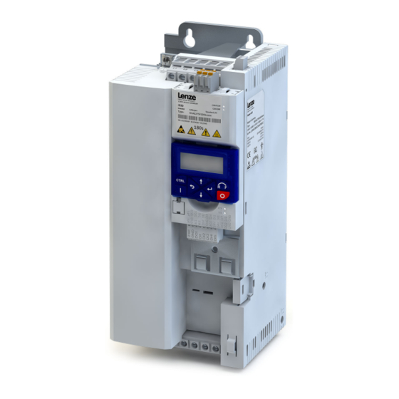
Lenze i550 Operating Instructions Manual
Cabinet frequency inverter 0.25-132 kw
Hide thumbs
Also See for i550:
- Commissioning manual (704 pages) ,
- Project planning manual (264 pages) ,
- Mounting and switch-on instructions (212 pages)
Advertisement
Table of Contents
- 1 General Information
- 2 Identification of the Products
- 3 Safety Instructions
- 4 Technical Data
- 5 Standards and Operating Conditions
- 6 Mechanical Installation
- 7 Important Notes
- 8 Electrical Installation
- 9 Brake Resistor Connection
- 10 Functional Safety
- 11 Initial Switch-On
- 12 Troubleshooting
- 13 Error Codes
- 14 Led Status
- Download this manual
Advertisement
Table of Contents


Need help?
Do you have a question about the i550 and is the answer not in the manual?
Questions and answers