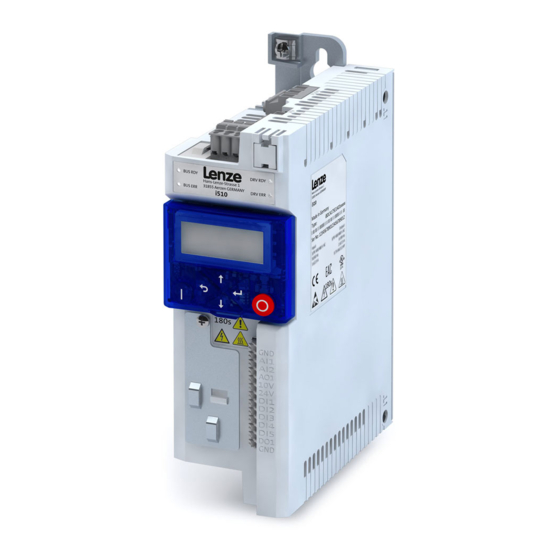
Lenze i510 Operation Manual
I500 inverter series cabinet
Hide thumbs
Also See for i510:
- Commissioning (487 pages) ,
- Service manual (250 pages) ,
- Mounting and switch-on instructions (67 pages)

Related Manuals for Lenze i510


Summary of Contents for Lenze i510
- Page 1 Inverter i500 Inverter i510 / i550 - Cabinet Operation Manual PRELIMINARY SW-Version 02.01...
-
Page 2: Table Of Contents
Easy Starter & USB adapter......................27 Commissioning procedure ..........................28 General parameter setup (Favorites) ......................29 5.4.1 Diagnostic ............................29 5.4.2 Basic setup ............................29 Lenze · Inverter i510 / i550 - Cabinet · Operation Manual · 0.4 EN · 02/2016... - Page 3 V/f: Override point of field weakening ..................... 60 6.5.7 Rotation restriction .......................... 61 6.5.8 Switching frequency ......................... 61 6.5.9 Motor thermal overload (i2xt) ......................62 6.5.10 Motor temperature sensor ......................63 Lenze · Inverter i510 / i550 - Cabinet · Operation Manual · 0.4 EN · 02/2016...
- Page 4 8.1.2 Status word ............................ 105 8.1.3 Speed setpoint / Actual Speed ....................... 105 Legacy Lenze Format ..........................106 8.2.1 Control word C135 ......................... 106 Lenze · Inverter i510 / i550 - Cabinet · Operation Manual · 0.4 EN · 02/2016...
- Page 5 Maintenance ........................125 10.1 Routine inspections ............................ 125 10.2 Product support ............................125 Decommissioning ......................126 11.1 Safety instructions ............................126 11.2 Removal and disposal ..........................126 Lenze · Inverter i510 / i550 - Cabinet · Operation Manual · 0.4 EN · 02/2016...
-
Page 6: About This Manual
The procedural notes and circuit details described in this operation manual are only proposals. It is up to the user to check whether they can be adapted to the particular applications. Lenze does not take any responsibility for the suitability of the procedures and circuit proposals described. -
Page 7: Parameter Description
Parameter witch are not visible on the keypad are marked in the manual as P (Without number) Parameters or selections with marking (*) are not available on all control unit types. Example: Lenze · Inverter i510 / i550 - Cabinet · Operation Manual · 0.4 EN · 02/2016... -
Page 8: Safety Information
WARNING indicates a hazardous situation which, if not avoided, could result in death or serious injury. CAUTION! CAUTION indicates a hazardous situation which, if not avoided, could result in minor or moderate injury. Lenze · Inverter i510 / i550 - Cabinet · Operation Manual · 0.4 EN · 02/2016... -
Page 9: Elements Of A Safety Message
After switching off the mains voltage wait at least 180s before starting to work on the device. High leakage current Carry out fixed installation and PE connection in compliance with standard EN 61800−5−1 ! Lenze · Inverter i510 / i550 - Cabinet · Operation Manual · 0.4 EN · 02/2016... -
Page 10: Basic Safety Measures
Always check if the procedural notes and circuit details described in this document can be adapted to the particular application. Refer to the i500 Commissioning manual for the parameterization of technically sophisticated applica- tions. Lenze · Inverter i510 / i550 - Cabinet · Operation Manual · 0.4 EN · 02/2016... -
Page 11: Electromagnetic Influences
Apart from using a residual current device (RCD), other protective measures can be taken as well, e.g. electrical isolation by double or reinforced insulation or isolation from the supply system by means of a transformer. Lenze · Inverter i510 / i550 - Cabinet · Operation Manual · 0.4 EN · 02/2016... -
Page 12: Product Description
The wide-ranging modular system enables various product configurations depending on machine require- ments. i500 can be used for wide range of applications: Pumps and fans, conveyor, travelling, winding, shaper, tool and hoist drives… Lenze · Inverter i510 / i550 - Cabinet · Operation Manual · 0.4 EN · 02/2016... -
Page 13: I500 Inverter Types
Mechanical Brake management low-wear brake control Dynamic braking through brake re- sistance PID controller, Motor potentiometer, Flying restart Safety technology Safe torque off (STO) Lenze · Inverter i510 / i550 - Cabinet · Operation Manual · 0.4 EN · 02/2016... -
Page 14: Overview
6) X105 – Motor connection 14) Shield connections for control connections 7) X216 – Network (Option) 15) IT screw (from 0.55 kW) 8) Switch between CANopen/Modbus Lenze · Inverter i510 / i550 - Cabinet · Operation Manual · 0.4 EN · 02/2016... -
Page 15: I550 Inverter Overview
7) X105 – Motor and brake resistor connection 16) PE / Ground connection 8) X109 – PTC input 17) IT screw (from 0.55 kW) 9) X2xx – Network (Option) Lenze · Inverter i510 / i550 - Cabinet · Operation Manual · 0.4 EN · 02/2016... -
Page 16: Typecode
1. Power unit – type code (P192:5) and serial number (P192:7) 2. Control unit – type code (P192:4) and serial number (192:6) 3. Complete inverter – Product code (P190:1) and serial number(P190:2) Lenze · Inverter i510 / i550 - Cabinet · Operation Manual · 0.4 EN · 02/2016... -
Page 17: Installation
The integrity of all earth / ground connections should be periodically checked. Lenze · Inverter i510 / i550 - Cabinet · Operation Manual · 0.4 EN · 02/2016... -
Page 18: Wiring Overview I510
For 400V connection see next subchapter “4.2.2 Wiring overview i550” on page 19. For connections to other electricity supply systems refer to separate manual: i500 Mounting and switch-on instructions Lenze · Inverter i510 / i550 - Cabinet · Operation Manual · 0.4 EN · 02/2016... -
Page 19: Wiring Overview I550
For 230V connection see next previous subchapter “4.2.1 Wiring overview i510” on page 18 For connections to other electricity supply systems refer to separate manual: i500 Mounting and switch-on instructions Lenze · Inverter i510 / i550 - Cabinet · Operation Manual · 0.4 EN · 02/2016... -
Page 20: Control Wiring I510/I550
STO (safety) ground / earth reference – optional optional STO (safety) input B *Terminal are internally connected and ca be used for loop wiring Lenze · Inverter i510 / i550 - Cabinet · Operation Manual · 0.4 EN · 02/2016... -
Page 21: Default Control Setup
(Preset 2) 25Hz 20Hz (Preset 1) -35Hz -50Hz* Ready to run (Relay) *Default values 50Hz/60Hz are depending on the Type Code! Fig. 8: Control scheme Lenze · Inverter i510 / i550 - Cabinet · Operation Manual · 0.4 EN · 02/2016... -
Page 22: Commissioning
Parameter management This intuitive app Emulates the inverter keypad on a smartphone. Adjustment to simple applications such as a conveyor belt. I5MADW000000S Lenze · Inverter i510 / i550 - Cabinet · Operation Manual · 0.4 EN · 02/2016... -
Page 23: Keypad
AUTO • Up/Down arrows are inactive (speed control is external) Set • When blinking indicates that a setting or value has changed and needs to be entered Lenze · Inverter i510 / i550 - Cabinet · Operation Manual · 0.4 EN · 02/2016... - Page 24 I/O Setup Group 0 - Favorites contains links to the most commonly used parameters for initial commissioning and monitoring of the inverter for general applications. Lenze · Inverter i510 / i550 - Cabinet · Operation Manual · 0.4 EN · 02/2016...
- Page 25 Press >3s (Saving parameter) icon on the LCD display will stop blinking when Parameters Saved saving is complete. P . S A V E D AUTO SET8 Lenze · Inverter i510 / i550 - Cabinet · Operation Manual · 0.4 EN · 02/2016...
- Page 26 Parameters Saved P . S A V E D AUTO SET8 Fig. 11: Navigation in Group 1-7 Lenze · Inverter i510 / i550 - Cabinet · Operation Manual · 0.4 EN · 02/2016...
-
Page 27: Easy Starter & Usb Adapter
Easy Starter software (version from 1.8.0.0) PC or laptop with free USB port The Easy Starter software is available for free - see download area on the Lenze web (www.lenze.com). Observe the system requirements and installation procedure on the download page. Procedure 1. -
Page 28: Commissioning Procedure
Adjust the corresponding parameter to tune your application. Diagnose & troubleshooting 9 Troubleshooting, page 117 Status LED and error messages are available for troubleshooting. Lenze · Inverter i510 / i550 - Cabinet · Operation Manual · 0.4 EN · 02/2016... -
Page 29: General Parameter Setup (Favorites)
P220:0 Basic Setup Acceleration time 1 deceleration time (see illus- P221:0 Basic Setup Deceleration time 1 tration below). P211:0 P210:0 P210:0 Time Fig. 12: Motor settings Lenze · Inverter i510 / i550 - Cabinet · Operation Manual · 0.4 EN · 02/2016... -
Page 30: Motor Control Modes
Type Name Default setting Unit application requires that the motor is running only in P304:0 Motor Control Rotational restriction 1: Forwards/Reverse – one direction: Lenze · Inverter i510 / i550 - Cabinet · Operation Manual · 0.4 EN · 02/2016... - Page 31 Inverter enable 1: TRUE – P400:2 I/O Setup Run/Stop 11: Digital input 1 – P400:3 I/O Setup Quick Stop [QSP] 0: Not connected – Lenze · Inverter i510 / i550 - Cabinet · Operation Manual · 0.4 EN · 02/2016...
- Page 32 P430:2 I/O Setup AI1 frequency @ min 0.0 ing. 50.0/60.0 *Typecode P430:3 I/O Setup AI1 frequency @ max dependent Lenze · Inverter i510 / i550 - Cabinet · Operation Manual · 0.4 EN · 02/2016...
- Page 33 P450:1 I/O Setup Preset 01 20.0 P450:2 I/O Setup Preset 02 40.0 50.0/60.0 *Typecode P450:3 I/O Setup Preset 03 dependent P450:4 I/O Setup Preset 04 Lenze · Inverter i510 / i550 - Cabinet · Operation Manual · 0.4 EN · 02/2016...
-
Page 34: Function & Parameter Description
Keypad Setup Brake control Brake energy management Keypad Flying start User group Parameter set Fault reaction Access control Lenze · Inverter i510 / i550 - Cabinet · Operation Manual · 0.4 EN · 02/2016... - Page 35 Parameter witch are not visible on the keypad are marked in the manual as P (Without number) Parameters or selections with marking (*) are not available on all control unit types. Example: Lenze · Inverter i510 / i550 - Cabinet · Operation Manual · 0.4 EN · 02/2016...
-
Page 36: Control Concept
To select the network as setpoint source in network mode (P400:37 = TRUE) use the “Default setpoint source” (P201:1-2) or the corresponding control bits (AC Drive Control Word, C135 Control Word, NET- WordIN1). Lenze · Inverter i510 / i550 - Cabinet · Operation Manual · 0.4 EN · 02/2016... - Page 37 Modes of operation P301:0 (0x6060:0) Modes of operation P301:0 (0x6060:0) -2 = MS-Velocity mode 2 = Velocity Mode (vl) (Manufacturer specific - Velocity mode (CiA402) Priority Priority Lenze · Inverter i510 / i550 - Cabinet · Operation Manual · 0.4 EN · 02/2016...
-
Page 38: Control Source
1 = Keypad ONLY … Other options / external triggers … Other options / external triggers The actual control source can be seen in P125:1 Lenze · Inverter i510 / i550 - Cabinet · Operation Manual · 0.4 EN · 02/2016... -
Page 39: Control Examples
Invert rotation 50 Hz P221.00 Deceleration time 1 0 Hz Motor Frequency Stop method based P220:0 on P203:3 setting -50 Hz Acceleration time 1 Lenze · Inverter i510 / i550 - Cabinet · Operation Manual · 0.4 EN · 02/2016... - Page 40 Stop P221:0 50 Hz Deceleration time 1 0 Hz Motor Frequency Stop method based P220:0 on P203:3 setting -50 Hz Acceleration time 1 Lenze · Inverter i510 / i550 - Cabinet · Operation Manual · 0.4 EN · 02/2016...
- Page 41 Run Reverse (CCW) P400:9 50 Hz Stop method based on P203:3 0 Hz Motor Speed Stop method P220:0 Acceleration based on -50 Hz time 1 P203:3 Lenze · Inverter i510 / i550 - Cabinet · Operation Manual · 0.4 EN · 02/2016...
-
Page 42: Rotation Direction
* If the input is bidirectional (-10V..10V), the direction FWD/REV of the Start and Run are ignored ** Only positive value can be entered ***Direction changes only if speedsetpoint is higher than fmin! Lenze · Inverter i510 / i550 - Cabinet · Operation Manual · 0.4 EN · 02/2016... -
Page 43: Group 1 - Diagnostics
-- ... [Actual value] ... -- VAC Actual motor voltage P107:0 0x6077:0 Actual torque i510 i550 -- ... [Actual value] ... -- % Actual motor torque (100% = Max. torque) Lenze · Inverter i510 / i550 - Cabinet · Operation Manual · 0.4 EN · 02/2016... -
Page 44: Output Power
-- ... [Actual value] ... -- V Actual output voltage of A01 P112:2 0x2DAA:2 Current i510 i550 -- ... [Actual value] ... -- mA Actual output current of A01 Lenze · Inverter i510 / i550 - Cabinet · Operation Manual · 0.4 EN · 02/2016... -
Page 45: Analog Output 2 Value
Bit # description: PID status (Bit coded) 0: Process controller off 1: PID output set to 0 2: PID I-component set to 0 Lenze · Inverter i510 / i550 - Cabinet · Operation Manual · 0.4 EN · 02/2016... -
Page 46: Motor Protection I2Xt
Cause of quick stop i510 i550 Bit # description: Cause of quick stop (Bit coded) 0: Flexible I/O: configuration 1: Network 2: Axis command Lenze · Inverter i510 / i550 - Cabinet · Operation Manual · 0.4 EN · 02/2016... -
Page 47: Device Utilization (Ixt)
-- ... [Actual value] ... -- ns Total time that control unit was powered on. It includes the time where the control section is powered by USB adapter. Lenze · Inverter i510 / i550 - Cabinet · Operation Manual · 0.4 EN · 02/2016... -
Page 48: History Buffer
-- ... [Actual value] ... -- Example: IDFW5AA P190:12 0x2000:12 Power Unit bootloader vers. i510 i550 -- ... [Actual value] ... -- Lenze · Inverter i510 / i550 - Cabinet · Operation Manual · 0.4 EN · 02/2016... -
Page 49: Device Name
The inverter can be controlled from several sources such as terminals (Digital Inputs), Fieldbus or Keypad. 0: Flexible Control Start / Stop and rotation direction configured in P400.xx Lenze · Inverter i510 / i550 - Cabinet · Operation Manual · 0.4 EN · 02/2016... -
Page 50: Default Setpoint
Two digital inputs (increase/decrease) control the setpoint P201:2 0x2860:2 PID control : Default setpoint source i510 i550 1: Keypad PID setpoint Default PID setpoint (Reference see P201:1) Lenze · Inverter i510 / i550 - Cabinet · Operation Manual · 0.4 EN · 02/2016... -
Page 51: Keypad Setpoints
Inverter apply the DC Brake when the start is initiated, before beginning rotation of the motor. When the DC Brake delay time has elapsed the Lenze · Inverter i510 / i550 - Cabinet · Operation Manual · 0.4 EN · 02/2016... -
Page 52: Start On Power Up
1: On 0: Off Already present start/run signal upon application of mains power are ig- nored. The inverter needs a new start/run signal to start. Lenze · Inverter i510 / i550 - Cabinet · Operation Manual · 0.4 EN · 02/2016... -
Page 53: Voltage Configuration
0.0 ... [0.0] ... 599.0 Hz Minimum motor frequency P211:0 0x2916:0 Maximum frequency i510 i550 0.0 ... [Type Code dependent] ... Maximum motor frequency 599.0 Hz Lenze · Inverter i510 / i550 - Cabinet · Operation Manual · 0.4 EN · 02/2016... -
Page 54: Acceleration / Deceleration
0.0 ... [5.0] ... 3600.0 s Acceleration time 2 for the output frequency to decrease from Maxi- mum Frequency (P211:0) to 0.0 Hz Note: MOP use ACC/DEC2 Lenze · Inverter i510 / i550 - Cabinet · Operation Manual · 0.4 EN · 02/2016... -
Page 55: Quickstop Ramp Time (Qsp)
(P211:0) to 0.0 Hz Note: In Cia402 Velocity mode (P301:0 = [2] Velocity mode (vl) ) the quick stop deceleration time is defined by P790:0. Lenze · Inverter i510 / i550 - Cabinet · Operation Manual · 0.4 EN · 02/2016... -
Page 56: Group 3 - Motor Control
2. Set the V/f characteristic shape: P302:0 to “Eco [3]” 3. Advanced Motor setup: Set motor parameter (6.5.12 Motor parameter, page 65) or select the motor out of the Lenze catalogue (In case of a Lenze motor & Easy Starter). 4. Set VFC-ECO Minimum Voltage: P330:1 Set VFC-ECO Minimum Voltage ... - Page 57 1. Set the motor control mode: P300:0 to “Sensorless vector control [4]” 2. Advanced Motor setup: Set motor parameter (6.5.12 Motor parameter, page 65) or select the motor out of the Lenze catalogue (In case of a Lenze motor & Easy Starter). NOTICE! For the usage of SLVC the following restrictions apply: ...
- Page 58 0: Mode no change/assigned No operation mode selected. Drive disabled. 2: Velocity mode (vl): CiA402 velocity mode. Control word 0x6040 is following CiA402 standard Lenze · Inverter i510 / i550 - Cabinet · Operation Manual · 0.4 EN · 02/2016...
-
Page 59: V/F: Curve Setting
This parameter describes the operating point in relation to a chosen per- centage value of Base voltage (P303:1) at Base frequency (P303:2). See graphic above. Lenze · Inverter i510 / i550 - Cabinet · Operation Manual · 0.4 EN · 02/2016... -
Page 60: V/F: Slip Compensation
See Easy starter for setup and more information 6.5.6 V/f: Override point of field weakening See Easy starter for setup and more information Lenze · Inverter i510 / i550 - Cabinet · Operation Manual · 0.4 EN · 02/2016... -
Page 61: Rotation Restriction
Optimized for best inverter efficiency (asymmetrical modulation). Switching frequency is fixed. 21, 22, 23: Optimized for best inverter performance (symmetrical modulation) Variable switching frequency: Inverter reduces the switching frequency if Lenze · Inverter i510 / i550 - Cabinet · Operation Manual · 0.4 EN · 02/2016... -
Page 62: Motor Thermal Overload (I2Xt)
Notes: - For compliance with UL the user must enable this function or use an appropriate PTC to protect the motor. Lenze · Inverter i510 / i550 - Cabinet · Operation Manual · 0.4 EN · 02/2016... -
Page 63: Motor Temperature Sensor
Inverter will go to Trouble state and ramp down the motor with the Quick Stop Ramp time. 3: Fault Inverter will go to Fault state and stop the motor with a coast stop. Lenze · Inverter i510 / i550 - Cabinet · Operation Manual · 0.4 EN · 02/2016... -
Page 64: Skip Frequency
0.0 ... [0.0] ... 599.0 Hz Skip frequency 3 P317:6 0x291F:6 Skip bandwidth 3 i510 i550 0.0 ... [0.0] ... 10.0 Hz Skip bandwidth 3 Lenze · Inverter i510 / i550 - Cabinet · Operation Manual · 0.4 EN · 02/2016... -
Page 65: Motor Parameter
The identification may take several seconds/minutes and measures the motor characteristic and calculates motor control parameters (Speed/Current control loop) based on the identified parameters. Lenze · Inverter i510 / i550 - Cabinet · Operation Manual · 0.4 EN · 02/2016... -
Page 66: Speed Limitation
If the limitation cannot correct the condition and the inverter remains in current limit for too long, it will trip with I2T motor error. P324:0 0x6073:0 Max current i510 i550 0.0 ... [200.0] ... 3000.0 % Maximum motor current in % of P323:0 Lenze · Inverter i510 / i550 - Cabinet · Operation Manual · 0.4 EN · 02/2016... -
Page 67: Torque Limitation
Mode selection for digital input functionalities (DI4 / DI3) 1: Encoder (AB) (*) 0x2C42:6 Actual velocity i550 -- ... [Actual value] ... -- rpm Actual velocity feedback of encoder Lenze · Inverter i510 / i550 - Cabinet · Operation Manual · 0.4 EN · 02/2016... -
Page 68: Overspeed Monitoring
0.0 ... [Type Code dependent] ... Overcurrent threshold 1000.0 A P353:2 0x2D46:2 Reaction i510 i550 3:Fault Overcurrent fault reaction (Reference see P310:1) Lenze · Inverter i510 / i550 - Cabinet · Operation Manual · 0.4 EN · 02/2016... -
Page 69: Group 4 - I/O Setup
The JOG functions have priority over Stop commands. If the inverter is currently JOGGING, pressing the STOP key on the keypad or triggering STOP command will NOT stop the motor! Lenze · Inverter i510 / i550 - Cabinet · Operation Manual · 0.4 EN · 02/2016... - Page 70 0: FALSE disables this functionality P400:4 0x2631:4 Reset fault i510 i550 12:Digital input 2 Trigger for fault reset (Reference see P400:1) FALSE->TRUE transition the faults will be reset. Lenze · Inverter i510 / i550 - Cabinet · Operation Manual · 0.4 EN · 02/2016...
- Page 71 - Set the signal to 0: FALSE to disable the function - If a bipolar input (-10V..+10V) is used the direction is controlled by the reference signal Lenze · Inverter i510 / i550 - Cabinet · Operation Manual · 0.4 EN · 02/2016...
- Page 72 Rotation inversion signal (Reference see P400:1) State: TRUE: target reference setpoint is inverted (i.e. times -1) FALSE: the target reference setpoint in not inverted Lenze · Inverter i510 / i550 - Cabinet · Operation Manual · 0.4 EN · 02/2016...
-
Page 73: Setpoint Selection
14:Digital input 4 Preset frequency setpoint selection bit 0 (Reference see P400:1) Combination Example: bit0 and bit2 result in preset frequency 5 Lenze · Inverter i510 / i550 - Cabinet · Operation Manual · 0.4 EN · 02/2016... -
Page 74: Motor Potentiometer
Process controller (PID) i510 i550 -300.00 ... [0.00] ... 300.00 PUnit Process controller start value for MOP-Mode Note: Only active if P413:0 is set to 1 Lenze · Inverter i510 / i550 - Cabinet · Operation Manual · 0.4 EN · 02/2016... -
Page 75: User Defined Faults
0: Not inverted Inversion of Digital Input 1: Inverted P411:4 0x2632:4 Digital input 4 i510 i550 0: Not inverted Inversion of Digital Input 1: Inverted Lenze · Inverter i510 / i550 - Cabinet · Operation Manual · 0.4 EN · 02/2016... -
Page 76: Frequency Threshold Setup
48: NETWordIN2 - bit 14 69: TRUE when output frequency is negative 49: NETWordIN2 - bit 15 70: TRUE when the output frequency is > the frequency threshold Lenze · Inverter i510 / i550 - Cabinet · Operation Manual · 0.4 EN · 02/2016... - Page 77 (Reference see P420:1) (Reference list see P420:1) Note: Only with Application IO P421:1 0x2635:1 Relay i510 i550 0: Not inverted Inversion of Relay Output 1: Inverted Lenze · Inverter i510 / i550 - Cabinet · Operation Manual · 0.4 EN · 02/2016...
-
Page 78: Analog Input Settings
Configuration of Analog input signal 1 1: 0...5VDC 2: 2...10VDC Note: On i510 only current and unipolar voltage input available. 3: -10...+10VDC (*) 4: 4...20mA 5: 0...20mA Lenze · Inverter i510 / i550 - Cabinet · Operation Manual · 0.4 EN · 02/2016... - Page 79 Represents the maximum of the analog input value P431:6 0x2637:6 Analog input 2: Filter time i510 i550 0 ... [10] ... 10000 ms Analog input filter time constant Lenze · Inverter i510 / i550 - Cabinet · Operation Manual · 0.4 EN · 02/2016...
-
Page 80: Analog Output Settings
Analog output function1 1: Output frequency 2: Frequency setpoint Scaling factors: 3: Analog input 1 1: [0.1 Hz] 4: Analog input 2 2: [0.1 Hz] Lenze · Inverter i510 / i550 - Cabinet · Operation Manual · 0.4 EN · 02/2016... - Page 81 Setting x Scaling factor = Maximum analog output value: Example: Setting 500, 'Actual output frequency' Maximum analog output value = 500 x 0.1 Hz = 50Hz Lenze · Inverter i510 / i550 - Cabinet · Operation Manual · 0.4 EN · 02/2016...
-
Page 82: Preset Setpoints (Frequency, Pid)
0.0 ... [0.0] ... 599.0 Hz Preset frequency setpoint 15 P451:1-8 0x4022:1-8 Process controller preset 1-8 i510 i550 -300.00 ... [0.00] ... 300.00 PUnit Preset PID setpoint 1-8 Lenze · Inverter i510 / i550 - Cabinet · Operation Manual · 0.4 EN · 02/2016... -
Page 83: Group 5 - Fieldbus
3: Normal bi-drectional PID is disabled 4: Reverse bi-directional 1: Normal operation Direct acting system. Motor needs to increase the speed to increase the Lenze · Inverter i510 / i550 - Cabinet · Operation Manual · 0.4 EN · 02/2016... - Page 84 20 ... [400] ... 6000 ms PID controller adjustment time Tn - Value "6000 ms" deactivates the I component. - With P400:47 the I Part can be disabled Lenze · Inverter i510 / i550 - Cabinet · Operation Manual · 0.4 EN · 02/2016...
-
Page 85: Pid Triggers
(Time from 0 to Maximum frequency) P606:2 0x4021:2 Deceleration time i510 i550 0.0 ... [1.0] ... 3600.0 s PID output Deceleration time (Time from Maximum frequency) Lenze · Inverter i510 / i550 - Cabinet · Operation Manual · 0.4 EN · 02/2016... -
Page 86: Pid Influence
Rinse function: Start the inverter periodically during sleep mode to prevent accumulation of deposits in the piping or the pump system. See Easy starter for setup and more information Lenze · Inverter i510 / i550 - Cabinet · Operation Manual · 0.4 EN · 02/2016... -
Page 87: Group 7 - Auxiliary Functions
Save OEM data to EPM i510 i550 0: Off / ready Saves RAM values to the OEM section of the EPM. (Reference see P700:1) Lenze · Inverter i510 / i550 - Cabinet · Operation Manual · 0.4 EN · 02/2016... -
Page 88: Keypad Setup
3. Manually triggered (I.e. Digital IO) The Trigger P400:5 activates the DC brake manually. Note: The DC brake is ON as long as the function is triggered! Lenze · Inverter i510 / i550 - Cabinet · Operation Manual · 0.4 EN · 02/2016... - Page 89 0x2B84:3 Auto enable threshold i510 i550 0.0 ... [0.0] ... 599.0 Hz Frequency Threshold to apply the DC Brake during deceleration of mo- tor. Lenze · Inverter i510 / i550 - Cabinet · Operation Manual · 0.4 EN · 02/2016...
-
Page 90: Regenerative Energy Management
Avoid long braking times using the compound braking. The Compound Braking function must not be used with vertical conveyors (hoists) or with active loads! Lenze · Inverter i510 / i550 - Cabinet · Operation Manual · 0.4 EN · 02/2016... - Page 91 2: Resistor and deceleration override 1: Fixed value Chopper On threshold 2: P706:3 Reduced threshold 3: P706:2 Active threshold 4: P706:4 Additional frequency 4: Resistor/compound/override Lenze · Inverter i510 / i550 - Cabinet · Operation Manual · 0.4 EN · 02/2016...
- Page 92 Configuration of the brake resistor warning reaction (Reference see P310:1) P707:11 0x2550:11 Response to error i550 3:Fault Configuration of the brake resistor error reaction (Reference see P310:1) Lenze · Inverter i510 / i550 - Cabinet · Operation Manual · 0.4 EN · 02/2016...
-
Page 93: Loss Of Load Detection
The Behavior from the keypad and PC tool are the same. If the PIN1/PIN2 is lost the only way to unlock the device is to reset the device back to factory settings with the SW-tool. Lenze · Inverter i510 / i550 - Cabinet · Operation Manual · 0.4 EN · 02/2016... -
Page 94: Favorites Setup
The inverter can switch between 4 sets of 32 parameters. The 32 parameters can be freely configured. See Easy starter for setup and more information Lenze · Inverter i510 / i550 - Cabinet · Operation Manual · 0.4 EN · 02/2016... -
Page 95: Fieldbus
Used for EtherNet/IP Lenze Legacy (Predefined mapping) Netword IN/Out (Configurable mapping) See chapter 8 Drive Profile on page 103 for details. Lenze · Inverter i510 / i550 - Cabinet · Operation Manual · 0.4 EN · 02/2016... -
Page 96: Canopen Quick Start
To do so you must set bit 31 in 0x1400:1. This will unlock the PDO for editing (makes the PDO invalid). RPDO1 Default COB ID: 0x200+the node ID (hex) Lenze · Inverter i510 / i550 - Cabinet · Operation Manual · 0.4 EN · 02/2016... - Page 97 12. Controlling the inverter: - With the default IO-setting DI1 need to be asserted (Run/Stop). - Set Bit 4 of NetWordIN1 to start the drive Lenze · Inverter i510 / i550 - Cabinet · Operation Manual · 0.4 EN · 02/2016...
- Page 98 12 Actual speed = 0 13 Not connected 13 Invert rotation 14 Not connected 14 Holding brake release 15 Not connected 15 Safe Torque Off Lenze · Inverter i510 / i550 - Cabinet · Operation Manual · 0.4 EN · 02/2016...
-
Page 99: Modbus Quick Start
4 is not transmitted in the message). It is important to note that Lenze complies with base 1 addressing of Modbus. So there is a 1 offset in the address transmitted to the address requested (i.e. 0000 would be register 40001, 0001 would be 40002, 0002 would be 40003, etc.). - Page 100 0x61 (Bit0 - Run Forward, Bit5 - Network Control, Bit6-Network Setpoint) 10. Set speed setpoint: Set register 42102 (Network Frequency Setpoint ABS[0.01Hz]) with the setpoint with function code 0x06 Example: 1234 = 12.34 Hz Lenze · Inverter i510 / i550 - Cabinet · Operation Manual · 0.4 EN · 02/2016...
-
Page 101: Profibus Quick Start
Actual motor current [0.1A] P104 (0x2D88) The configuration of the process data is automatically sent to the drive. Also the Bit-configuration of NetWordIN1 and NetWordOUT1. Lenze · Inverter i510 / i550 - Cabinet · Operation Manual · 0.4 EN · 02/2016... - Page 102 - Set Bit 4 of “Lenze control word (NetWordIN1)” to start the drive Per default the watchdog timeout response for the communication is set to fault (P515:1, 0x2859:1). Lenze · Inverter i510 / i550 - Cabinet · Operation Manual · 0.4 EN · 02/2016...
-
Page 103: Drive Profile (Fieldbus)
- Fixed Mapping Common NetWordIn4 0x4008:4 MAPPING P440:2, P441:2 Source for AO1/AO2 NetWordOut1 0x400A:1 ß Mapping P420:10-25 Drive States Configuration / Asyclic / Direct parameter access Parameter Lenze · Inverter i510 / i550 - Cabinet · Operation Manual · 0.4 EN · 02/2016... -
Page 104: Cia402
Fault reset Transition from 0 to 1 resets fault Operation mode specific Reserved Reserved Reserved Reserved Holding brake release 1 = Releases holding brake Reserved Lenze · Inverter i510 / i550 - Cabinet · Operation Manual · 0.4 EN · 02/2016... -
Page 105: Status Word
-- ... [0] ... -- rpm CiA402 network speed setpoint P783:0 0x6044:0 Velocity actual value vl i510 i550 -- ... [Actual value] ... -- rpm CiA402 actual speed Lenze · Inverter i510 / i550 - Cabinet · Operation Manual · 0.4 EN · 02/2016... -
Page 106: Legacy Lenze Format
Network user fault Fault reset (01) 0->1 edge causes TRIP reset Reserved Reserved DC Brake Active 0 = Not Active 1 = Active Reserved Lenze · Inverter i510 / i550 - Cabinet · Operation Manual · 0.4 EN · 02/2016... -
Page 107: Status Word
0101 = DC Brake Active 0110 = Operation Enabled 0111 = Message Active 1000 = FAULT Over-temperature warning DC Bus overvoltage Rotation (0-CW/1-CCW) Ready for Operation Lenze · Inverter i510 / i550 - Cabinet · Operation Manual · 0.4 EN · 02/2016... -
Page 108: Speed Setpoint / Actual Speed
Legacy actual speed Scaling RPM, unsigned P593:6 0x400C:6 Actual frequency i510 i550 -- ... [Actual value] ... -- Hz Legacy actual frequency Scaling 0.01Hz, unsigned Lenze · Inverter i510 / i550 - Cabinet · Operation Manual · 0.4 EN · 02/2016... -
Page 109: Ac Drive Profile
NOTE: Bit processed only when NetCtrl = 1 PID off (1 – off) NOTE: Bit processed only when NetCtrl = 1 DC Brake NOTE: Bit processed only when NetCtrl = 1 Lenze · Inverter i510 / i550 - Cabinet · Operation Manual · 0.4 EN · 02/2016... -
Page 110: Status Word
0 = NOT in Current Limit 1 = in Current Limit DC Brake Active 0 = DC brake NOT active 1 = DC brake active Lenze · Inverter i510 / i550 - Cabinet · Operation Manual · 0.4 EN · 02/2016... -
Page 111: Speed Setpoint / Actual Speed
Legacy actual speed Scaling RPM, unsigned P593:6 0x400C:6 Actual frequency i510 i550 -- ... [Actual value] ... -- Hz Legacy actual frequency Scaling 0.01Hz, unsigned Lenze · Inverter i510 / i550 - Cabinet · Operation Manual · 0.4 EN · 02/2016... -
Page 112: Netword Configuration
Inverter Master (NETWordOut) NETWordOut1: Drive Status bits Value: 0x400A:1 (P591:1) Configuration: 0x2635:10-25 (P420:10-25) NETWordOut2: Switched by Sequencer Value: 0x400A:2 (P591:2) Configuration: Sequencer parameter Lenze · Inverter i510 / i550 - Cabinet · Operation Manual · 0.4 EN · 02/2016... -
Page 113: Networdin Configuration
47: PID integrator disabled 48: PID influence ramps active P505:2 0x400E:2 NETWordIN1.01 i510 i550 0:Not connected Function of Network Input Word Bit 1 (Reference see P505:0) Lenze · Inverter i510 / i550 - Cabinet · Operation Manual · 0.4 EN · 02/2016... - Page 114 Function of Network Input Word Bit 14 (Reference see P505:0) P505:16 0x400E:16 NETWordIN1.15 i510 i550 0:Not connected Function of Network Input Word Bit 15 (Reference see P505:0) Lenze · Inverter i510 / i550 - Cabinet · Operation Manual · 0.4 EN · 02/2016...
-
Page 115: Networdout Configuration
Function of Network Bit 9 (SW 02.01: New Default) (Reference see P420:1) P420:20 0x2634:20 NETWordOUT1 - bit 10 i510 i550 72:Setpoint speed reached Function of Network Bit 10 (Reference see P420:1) Lenze · Inverter i510 / i550 - Cabinet · Operation Manual · 0.4 EN · 02/2016... - Page 116 (Reference see P420:1) P420:25 0x2634:25 NETWordOUT1 - bit 15 i510 i550 55:Safe Torque Off Function of Network Bit 15 (SW 02.01: New Default) (Reference see P420:1) Lenze · Inverter i510 / i550 - Cabinet · Operation Manual · 0.4 EN · 02/2016...
-
Page 117: Troubleshooting
In general the LED CAN-ERR CAN-ERR CANopen error indicates error states: (Red) Warning Limit reached Node Guard Event Sync Message Error (Can only occur in state “Operational”) Lenze · Inverter i510 / i550 - Cabinet · Operation Manual · 0.4 EN · 02/2016... -
Page 118: Modbus Led Status Display
Not connected, PLC STOP or no data exchange Incorrect setting of station address, operation with de- fault values Watchdog expired – Unrecoverable fault PROFIBUS parameterization error PROFIBUS configuration error Lenze · Inverter i510 / i550 - Cabinet · Operation Manual · 0.4 EN · 02/2016... -
Page 119: Error History
Lowest number (01) is most recent number Pressing the button will toggle between the two screens described above. Pressing the buttons will navigate from Error 01 to Error 32. Lenze · Inverter i510 / i550 - Cabinet · Operation Manual · 0.4 EN · 02/2016... -
Page 120: Error History Easy Starter
9024 Error Motor shorted Load level fault (I2t, thermal state). (P308:1-3) 0x2350 9040 Configurable i2t motor Ixt fault. (P135:5) 0x2382 9090 Configurable ixt Fault Lenze · Inverter i510 / i550 - Cabinet · Operation Manual · 0.4 EN · 02/2016... - Page 121 Diagnosis receive message ring buffer error 0x7581 30081 Configurable Diag RX error (0x218B:0) There are to many parameters on the EPM. 0x7680 30336 Warning EPM full Lenze · Inverter i510 / i550 - Cabinet · Operation Manual · 0.4 EN · 02/2016...
- Page 122 EPM data. Fault reaction: 0x7691 30353 Error PU Data not matc The data will load to RAM. Troubleshooting: Factory setting need to be loaded (P700:1) Lenze · Inverter i510 / i550 - Cabinet · Operation Manual · 0.4 EN · 02/2016...
- Page 123 PDO map error CAN time-out Rx PDO 1 (0x2857:1) 0x8291 33425 Configurable Timeout RPDO1 CAN time-out Rx PDO 2 (0x2857:2) 0x8292 33426 Configurable Timeout RPDO2 Lenze · Inverter i510 / i550 - Cabinet · Operation Manual · 0.4 EN · 02/2016...
- Page 124 Max output frequency reached 0xFF56 65366 Warning Warn. Max. Freq For other faults reboot the inverter. If the problem can’t be resolved contact LENZE. Lenze · Inverter i510 / i550 - Cabinet · Operation Manual · 0.4 EN · 02/2016...
-
Page 125: Maintenance
10.2 Product support Lenze Service GmbH Breslauer Straße 3, D-32699 Extertal Germany Phone: 0080002446877 (24h helpline) Fax: +49 5154 82-1112 Email: service.de@lenze.com Lenze · Inverter i510 / i550 - Cabinet · Operation Manual · 0.4 EN · 02/2016... -
Page 126: Decommissioning
Recycle metal and plastic materials of the inverter. Ensure professional disposal of assembled PCBs. Observe all applicable national regulations for the disposal of waste electronic equipment. Lenze · Inverter i510 / i550 - Cabinet · Operation Manual · 0.4 EN · 02/2016... - Page 127 Lenze Drives GmbH Postfach 10 13 52, D-31763 Hameln Breslauer Straße 3, D-32699 Extertal Germany HR Lemgo B 6478 +49 5154 82-0 +49 5154 82-2800 lenze@lenze.com www.lenze.com Lenze Service GmbH Breslauer Straße 3, D-32699 Extertal Germany 0080002446877 (24 h Helpline) +49 5154 82-1112 service.de@lenze.com...
Need help?
Do you have a question about the i510 and is the answer not in the manual?
Questions and answers