
Related Manuals for Extron electronics DXP Series


Summary of Contents for Extron electronics DXP Series
- Page 1 Vertrieb von CAMBOARD Electronics DXP Series Switchers Serial Digital Video Matrix Switchers 68-595-01 Rev. B Printed in USA 10 04 www.camboard.de Tel. 07131 911201 ce-info@camboard.de Fax 07131 911203...
- Page 2 im Vertrieb von CAMBOARD Electronics Precautions Safety Instructions • English Warning This symbol is intended to alert the user of important operating and maintenance Power sources • This equipment should be operated only from the power source indicated on the product.
- Page 3 im Vertrieb von CAMBOARD Electronics Quick Start — Digital XPoint Matrix Switchers Installation Definitions The following terms are used throughout this Step 1 manual: Turn off power to the input and output devices, Tie — An input-to-output connection. and remove the power cords from them. Set of ties —...
- Page 4 im Vertrieb von CAMBOARD Electronics Quick Start — Digital XPoint Matrix Switchers, cont’d Quick Start button key Save a preset A. Press and hold the Preset button until the button begins to blink. = Blinking button 2 Seconds PRESET PRESET Toggle switch modes Press and hold the Preset button until it blinks.
-
Page 5: Table Of Contents
im Vertrieb von CAMBOARD Electronics Table of Contents Chapter 1 • Introduction ....................... 1-1 About the Digital XPoint Series Matrix Switchers ..........1-2 Features ........................... 1-3 Chapter 2 • Installation ......................2-1 Mounting the Switcher ....................2-2 Table or wall mounting ..................... 2-2 Rack mounting ........................ - Page 6 im Vertrieb von CAMBOARD Electronics Table of Contents, cont’d Chapter 4 • Programmer’s Guide ..................4-1 Host-to-Switcher Instructions ..................4-2 Switcher-Initiated Messages ..................4-2 Switcher Error Responses ....................4-3 Using the Command/Response Table ................ 4-3 Command/Response Table for SIS Commands .............
-
Page 7: Chapter 1 • Introduction
im Vertrieb von CAMBOARD Electronics Digital XPoint Matrix Switchers Chapter One Introduction About the Digital XPoint Series Matrix Switchers Features www.camboard.de Tel. 07131 911201 ce-info@camboard.de Fax 07131 911203... -
Page 8: About The Digital Xpoint Series Matrix Switchers
im Vertrieb von CAMBOARD Electronics Introduction Introduction, cont’d About the Digital XPoint Series Matrix Switchers The Extron Digital XPoint Series Matrix Switchers are serial digital interface (SDI) matrix switchers that distribute any SDI input to any combination of SDI outputs. The matrix switchers can route multiple input/output configurations simultaneously. -
Page 9: Features
im Vertrieb von CAMBOARD Electronics Features Inputs — 4 or 8 SDI video inputs on BNC connectors and 4 or 8 equalized and buffered loop-throughs on BNC connectors Outputs — 4 or 8 SDI video outputs with two buffered and equalized outputs each on BNC connectors Serial digital data rates from 143 Mb/s to 360 Mb/s —... - Page 10 im Vertrieb von CAMBOARD Electronics Introduction, cont’d Mounting flexibility — Mounting brackets make the 1U high switchers mountable in any conventional 19” wide rack, or under or through a desk or other furniture. Power supply — The 100 VAC to 240 VAC, autoswitchable, internal power supply of the Digital XPoint Series provides worldwide power compatibility.
-
Page 11: Chapter 2 • Installation
im Vertrieb von CAMBOARD Electronics Digital XPoint Matrix Switchers Chapter Two Installation Mounting the Switcher Cabling and Rear Panel Views www.camboard.de Tel. 07131 911201 ce-info@camboard.de Fax 07131 911203... -
Page 12: Mounting The Switcher
im Vertrieb von CAMBOARD Electronics Installation Installation, cont’d Mounting the Switcher The Digital XPoint Matrix Switcher comes with two sets of mounting brackets. One set is for mounting the switcher under a table or against a wall, and the other set is for rack mounting. -
Page 13: Cabling And Rear Panel Views
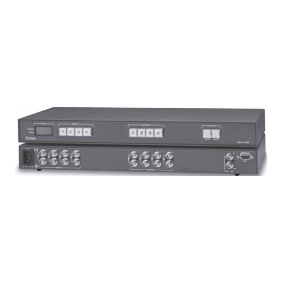
im Vertrieb von CAMBOARD Electronics Insert the switcher into the rack, aligning the holes in the mounting bracket with those of the rack. Secure the switcher to the rack using the supplied machine screws. Cabling and Rear Panel Views All connectors are on the rear panel. Figure 2-2 shows the rear of the Digital XPoint 88 Matrix Switcher. -
Page 14: Rs-232/422 Connection
im Vertrieb von CAMBOARD Electronics Installation, cont’d RS-232/422 connection RS-232/RS-422 port — If desired, connect a host device, such as a computer or touch panel control, to the Digital XPoint via this 9-pin D connector for serial RS-232/RS-422 control (figure 2-4). RS-232 Function RS-422 Function —... -
Page 15: External Sync Connection
im Vertrieb von CAMBOARD Electronics External sync connection When switching between inputs, the resulting image change should be seamless, or clean. The Digital XPoint Switchers can use an external signal to synchronize switching during the vertical sync interval. Without the external sync locking feature, switching between inputs can result in a brief rolling (sync loss) or a brief change in the picture size. -
Page 16: Power Connection
im Vertrieb von CAMBOARD Electronics Installation, cont’d Power connection AC power connector — Plug a standard IEC power cord into this connector to connect the switcher to a 90 to 240VAC, 50 Hz or 60 Hz power source. www.camboard.de Tel. 07131 911201 ce-info@camboard.de Digital XPoint Matrix Switchers •... -
Page 17: Chapter 3 • Operation
im Vertrieb von CAMBOARD Electronics Digital XPoint Matrix Switchers Chapter Three Operation Front Panel Controls and Indicators Front Panel Operations Worksheets www.camboard.de Tel. 07131 911201 ce-info@camboard.de Fax 07131 911203... -
Page 18: Front Panel Controls And Indicators
im Vertrieb von CAMBOARD Electronics Operation Operation, cont’d Front Panel Controls and Indicators All Digital XPoint controls and indicators are on the front panel (figure 3-1). The large, illuminated push buttons can be labeled with text and/or graphics. The buttons can be set to provide amber background illumination all the time or the background illumination can be set to off. -
Page 19: Control Buttons
im Vertrieb von CAMBOARD Electronics Control buttons Enter button — The Enter button saves changes when you set up a new configuration. To create a simple configuration, press the desired input button , press the desired output button(s) , and press the Enter button. Preset button —... -
Page 20: Switch Modes
im Vertrieb von CAMBOARD Electronics Operation, cont’d The current configuration and all presets are saved in non-volatile memory. When power is applied, the last current configuration is retrieved. The previous presets remain intact. If an error occurs during the self-test, the switcher locks up and will not operate. If your switcher locks up on power-up, call the Extron S Sales &... -
Page 21: Example 1A: Create A Set Of Ties In Enter Switch Mode
im Vertrieb von CAMBOARD Electronics Only one video input can be tied to an output, but multiple outputs can be tied to a single input. If a tie is made between an input and an output, and the selected output was previously tied to another input, the older tie is broken in favor of the newer tie. -
Page 22: Example 1B: Create A Set Of Ties In Quick Switch Mode
im Vertrieb von CAMBOARD Electronics Operation, cont’d Press and release the Enter button (figure 3-7). The input, output, and Enter buttons return to either unlit or to background illumination. The LCD returns to the default display. The current configuration is now defined as input 5 tied to output 3, output 4, and output 8. -
Page 23: Example 2: Add A Tie To A Set Of Ties
im Vertrieb von CAMBOARD Electronics Example 2: Add a tie to a set of ties The following steps show an example in which a new video tie is added to the current configuration in enter switch mode. Each step shows the front panel indications that result from your action. -
Page 24: Example 3: Remove A Tie From A Set Of Ties
im Vertrieb von CAMBOARD Electronics Operation, cont’d Example 3: Remove a tie from a set of ties The following steps show an example in which an existing tie is removed from the current configuration in enter switch mode. Each step shows the front panel indications that result from your action. -
Page 25: Viewing Source Status And The Current Configuration
im Vertrieb von CAMBOARD Electronics Viewing source status and the current configuration The LCD can sequentially display the sync status of an input and then the current configuration. To view the status for a specific input and then the current configuration, press and release the button for the desired input. -
Page 26: Using Presets
im Vertrieb von CAMBOARD Electronics Operation, cont’d Using presets The current configuration (configuration 0) can be saved as a preset in any of 16 preset memory addresses. On the DXP 88 SDI, presets 1 through 8 are assigned to the input buttons 1 through 8, and presets 9 through 16 are assigned sequentially to output buttons 1 through 8 (figure 3-17). - Page 27 im Vertrieb von CAMBOARD Electronics Press and release the output 1 button (figure 3-19). OUTPUTS CONTROL 1 2 3 4 5 6 7 8 ENTER PRESET Press and release the Output 1 button. (The The Enter button Output 1 button selects preset 9 on a DXP 88 SDI.) blinks red to indicate The button lights red.
-
Page 28: Example 5: View Or Recall A Preset
im Vertrieb von CAMBOARD Electronics Operation, cont’d Example 5: View or recall a preset The following steps show an example in which, on a DXP 44 SDI, the configuration of a saved preset is shown in the LCD and then recalled to become the current configuration. -
Page 29: Background Illumination
im Vertrieb von CAMBOARD Electronics To recall the preset, press and release the Enter button (figure 3-24). The configuration stored in memory location 5 is now the current configuration. CONTROL STATUS STATUS E X T RON ENTER PRESET D X P 4 4 X - Mo d e Press the Enter button to The LCD returns to the... -
Page 30: Worksheets
im Vertrieb von CAMBOARD Electronics Operation, cont’d Worksheets Rather than trying to remember the configuration for each preset, use worksheets to record this information. Make copies of the blank worksheet on page 3-17 and use one for each preset configuration. The form accommodates all of the Digital XPoint models. -
Page 31: Worksheet Example 2: Drawing Ties
im Vertrieb von CAMBOARD Electronics Worksheet example 2: Drawing ties Figure 3-26 continues from worksheet example 1 by showing the video ties that make up the configuration of preset 1. A solid ink line shows video ties from camera 1, a pencil line shows ties from camera 2, and dashed lines show the ties from cameras 3 and 4. -
Page 32: Worksheet Example 3: Test Configuration
im Vertrieb von CAMBOARD Electronics Operation, cont’d Worksheet example 3: Test configuration At night, the cable TV station in our fictional organization broadcasts a test pattern and sends the staff home. Figure 3-27 shows the test pattern configuration, with a test pattern from the VTR generated to all monitors (outputs 1, 2, 3, and 7) and to the broadcast equipment (output 4). -
Page 33: Configuration Worksheet
im Vertrieb von CAMBOARD Electronics Configuration worksheet www.camboard.de Tel. 07131 911201 ce-info@camboard.de Digital XPoint Matrix Switchers • Operation 3-17 Fax 07131 911203... - Page 34 im Vertrieb von CAMBOARD Electronics Operation, cont’d www.camboard.de Tel. 07131 911201 ce-info@camboard.de 3-18 Digital XPoint Matrix Switchers • Operation Fax 07131 911203...
-
Page 35: Chapter 4 • Programmer's Guide
im Vertrieb von CAMBOARD Electronics Digital XPoint Matrix Switchers Chapter Four Programmer’s Guide Host-to-Switcher Instructions Switcher-Initiated Messages Switcher Error Responses Using the Command/Response Table Command/Response Table for SIS Commands www.camboard.de Tel. 07131 911201 ce-info@camboard.de Fax 07131 911203... -
Page 36: Host-To-Switcher Instructions
The switcher-initiated messages are listed below (underlined). (C) Copyright 2001, Extron Electronics “DXP88”, Vx.xx The copyright message is initiated by the switcher when it is first powered on. Vx.xx is the firmware version number. -
Page 37: Switcher Error Responses
im Vertrieb von CAMBOARD Electronics Login Administrator Login User The switcher initiates the login message when a correct administrator or user password has been entered. If the user and administrator passwords are the same, the switcher defaults to administrator privileges. Reconfig The reconfig message is initiated by the switcher when a front panel operation has occurred, an audio gain adjustment has been completed, or a memory preset has... -
Page 38: Command/Response Table For Sis Commands
im Vertrieb von CAMBOARD Electronics Programmer’s Guide, cont’d Command/Response Table for SIS commands Symbol definitions = Carriage return/line feed = Carriage return (no line feed) • = Space = Input number 01 – 04 (Digital XPoint 44 SDI); 01 – 08 (Digital XPoint 88 SDI) = Output number 01 –... - Page 39 im Vertrieb von CAMBOARD Electronics Command/response table for SIS commands (Cont’d) Command ASCII Command Response Additional description (host to switcher) (switcher to host) Direct write of a global preset !… ! Spr Directly enters a global preset. Example: +7P5*2!5*3!3*6!4*1! Spr7 Creates preset 7, consisting of Input (I) 5 tied to Output (O) 2 and 3, I3 to O6, and I4 to O1.
- Page 40 im Vertrieb von CAMBOARD Electronics Programmer’s Guide, cont’d www.camboard.de Tel. 07131 911201 ce-info@camboard.de Digital XPoint Matrix Switchers • Programmer’s Guide Fax 07131 911203...
-
Page 41: Chapter 5 • Matrix Software
im Vertrieb von CAMBOARD Electronics Digital XPoint Matrix Switchers Chapter Five Matrix Software Matrix Switcher+ Control Program Using the Button-Label Generator Software www.camboard.de Tel. 07131 911201 ce-info@camboard.de Fax 07131 911203... -
Page 42: Matrix Switcher+ Control Program
To run the Matrix Switcher+ Control Program, double- click on the Matrix Switcher+ Control Program icon (shown at right) in the Extron Electronics group or folder. The comm port selection window (figure 5-1) appears. Figure 5-1 — Comm port selection window www.camboard.de... - Page 43 im Vertrieb von CAMBOARD Electronics Select either the comm port that is connected to the DXP’s RS-232/RS-422 port or Emulate and click OK. Although IP [LAN] is available for selection, the switcher does not have an Ethernet port. Do not select IP [LAN]. If you selected a comm port, proceed to step 3.
-
Page 44: Windows Buttons, Drop Boxes, And Trash
im Vertrieb von CAMBOARD Electronics Matrix Software, cont’d To make the control program easier to use, assign a device icon to each input and output. Click on a box that represents an input or output, and drag the desired icon onto the box from the icon palette that appears. To create a tie, click on and drag an input box to one or more output boxes. - Page 45 im Vertrieb von CAMBOARD Electronics Tools menu Assign device icons — Displays the complete set of input and output device icons. You can drag any of these icons to the input and output boxes. Edit device palette — Allows you to add your own device icon graphics.
-
Page 46: Using Emulation Mode
For information about program features, you can access the help program in any of the following ways: • From the Extron Electronics program folder or group, double- click on the Matrix Switcher+ Help icon (shown at right). • From within the Matrix Switcher+ Control Program, click on the Help menu on the main screen. -
Page 47: Using The Button-Label Generator Software
Switcher+ Control Program and is installed automatically when you install that program. By default, the installation program installs the program in the C:\MTRX50 directory, and the Button-Label Generator icon is placed in the “Extron Electronics” group or folder. To run the Button-Label Generator program, double-click on the Button-Label Generator icon (shown at right) in the Extron Electronics group or folder, and click on OK when prompted. - Page 48 im Vertrieb von CAMBOARD Electronics Matrix Software, cont’d www.camboard.de Tel. 07131 911201 ce-info@camboard.de Digital XPoint Matrix Switchers • Matrix Software Fax 07131 911203...
-
Page 49: Chapter 6 • Maintenance And Modifications
im Vertrieb von CAMBOARD Electronics Digital XPoint Matrix Switchers C hapter Six Maintenance and Modifications Hardware Upgrades and Maintenance Creating and Installing Button Labels www.camboard.de Tel. 07131 911201 ce-info@camboard.de Fax 07131 911203... -
Page 50: Hardware Upgrades And Maintenance
im Vertrieb von CAMBOARD Electronics Maintenance and Modifications Maintenance and Modifications, cont’d Hardware Upgrades and Maintenance This appendix contains procedures for performing hardware maintenance procedures such as swapping the RS-232 and RS-422 ports, installing a new firmware update, and replacing the fuse. Opening the switcher Before you can perform any of the hardware upgrade procedures, you must open the switcher. -
Page 51: Swapping The Serial Ports
im Vertrieb von CAMBOARD Electronics Swapping the serial ports The Digital XPoint Matrix Switchers are factory configured for RS-232 use. If you want to use RS-422 and the switcher is configured for RS-232, or if you want to use RS-232 and the switcher is configured for RS-422, do the following: Follow the instructions in Opening the switcher to gain access to the interior of your switcher. -
Page 52: Installing A Firmware Update
im Vertrieb von CAMBOARD Electronics Maintenance and Modifications, cont’d Installing a firmware update The integrated circuit device that contains the firmware for the switcher also contains the memory in which presets are saved. When you replace the IC, these settings are lost. You may want to record the presets before you replace the IC. -
Page 53: Replacing The Ac Fuse
im Vertrieb von CAMBOARD Electronics Reinitialize the switcher to recognize the new IC as follows: Connect the power cord to the AC power source. Press and hold the Enter button while you connect the power cord to the switcher. Continue to hold the Enter button until the power up sequence is completed (all front panel buttons cycle on and off from left to right lit green, right to left lit red, and left to right lit amber). -
Page 54: Creating And Installing Button Labels
im Vertrieb von CAMBOARD Electronics Maintenance and Modifications, cont’d Creating and Installing Button Labels Figure 6-5 on page 6-7 provides blank button labels. If desired, photocopy them or cut them out of the manual, write button information in each button area as desired, and put them in the switcher’s input or output button windows. - Page 55 im Vertrieb von CAMBOARD Electronics www.camboard.de Tel. 07131 911201 ce-info@camboard.de Digital XPoint Matrix Switchers • Maintenance and Modifications Fax 07131 911203...
- Page 56 im Vertrieb von CAMBOARD Electronics Maintenance and Modifications, cont’d www.camboard.de Tel. 07131 911201 ce-info@camboard.de Digital XPoint Matrix Switchers • Maintenance and Modifications Fax 07131 911203...
-
Page 57: Appendix A • Reference Information
im Vertrieb von CAMBOARD Electronics Digital XPoint Matrix Switchers A ppendix A Reference Information Specifications Part Numbers www.camboard.de Tel. 07131 911201 ce-info@camboard.de Fax 07131 911203... - Page 58 im Vertrieb von CAMBOARD Electronics Reference Information Reference Information, cont’d Specifications Video Routing DXP 44 SDI ......4 x 4 matrix DXP 88 SDI ......8 x 8 matrix Data rates ........143 Mbps, 177 Mbps, 270 Mbps, 360 Mbps Auto data rate lock ......
- Page 59 im Vertrieb von CAMBOARD Electronics Control/remote — switcher Serial control port ......RS-232 or RS-422, 9-pin female D connector Baud rate and protocol ....9600 baud, 8 data bits, 1 stop bit, no parity Serial control pin configurations 2 = TX, 3 = RX, 5 = GND Program control ......
-
Page 60: Digital Xpoint Part Numbers
im Vertrieb von CAMBOARD Electronics Reference Information, cont’d Part Numbers Digital XPoint part numbers Extron Part Part # Digital XPoint 44 SDI 60-402-01 Digital XPoint 88 SDI 60-401-01 -or- Matrix Switchers+ Control Program and Button-Label Generator Digital XPoint Matrix Switchers User’s Manual Optional accessories Extron Part Part #... - Page 61 Extron’s Warranty Extron Electronics warrants this product against defects in materials and workmanship for a period of three years from the date of purchase. In the event of malfunction during the warranty period...
- Page 62 PM Industrial Building 3-9-1 Kudan Minami The Netherlands Singapore 368363 Chiyoda-ku, Tokyo 102-0074 Japan 714.491.1500 +31.33.453.4040 +65.6383.4400 +81.3.3511.7655 www.extron.com Fax 714.491.1517 Fax +31.33.453.4050 Fax +65.6383.4664 Fax +81.3.3511.7656 www.camboard.de Tel. 07131 911201 ce-info@camboard.de © 2004 Extron Electronics. All rights reserved. Fax 07131 911203...
Need help?
Do you have a question about the DXP Series and is the answer not in the manual?
Questions and answers