Table of Contents
Advertisement
Quick Links
SIMOTION D410-
SIMOTION
SIMOTION D410-2
Manual
Valid for SIMOTION D410-2 DP
02/2012
2
___________________
Preface
___________________
Description
___________________
Operator control (hardware)
___________________
Interfaces
___________________
Technical data
___________________
Dimension drawings
___________________
Spare parts / accessories
___________________
Standards and approvals
___________________
ESD guidelines
1
2
3
4
5
6
A
B
Advertisement
Table of Contents

Related Manuals for Siemens SIMOTION D410-2


Summary of Contents for Siemens SIMOTION D410-2
- Page 1 ___________________ SIMOTION D410- Preface ___________________ Description ___________________ Operator control (hardware) SIMOTION ___________________ Interfaces ___________________ SIMOTION D410-2 Technical data ___________________ Dimension drawings Manual ___________________ Spare parts / accessories ___________________ Standards and approvals ___________________ ESD guidelines Valid for SIMOTION D410-2 DP 02/2012...
-
Page 2: Manual
Note the following: WARNING Siemens products may only be used for the applications described in the catalog and in the relevant technical documentation. If products and components from other manufacturers are used, these must be recommended or approved by Siemens. Proper transport, storage, installation, assembly, commissioning, operation and maintenance are required to ensure that the products operate safely and without any problems. -
Page 3: Preface
Contents of the Product Manual This document is part of the SIMOTION D documentation package. Scope The SIMOTION D410-2 Manual describes the SIMOTION D410-2 DP Control Unit. Note An independent SIMOTION D410 Manual is available for the SIMOTION D410 DP and SIMOTION D410 PN Control Units. - Page 4 My Documentation Manager Click the following link for information on how to compile documentation individually on the basis of Siemens content and how to adapt this for the purpose of your own machine documentation: http://www.siemens.com/mdm SIMOTION D410-2...
- Page 5 Preface Training Click the following link for information on SITRAIN - Siemens training courses for automation products, systems and solutions: http://www.siemens.com/sitrain FAQs Frequently Asked Questions can be found in SIMOTION Utilities & Applications, which are included in the scope of delivery of SIMOTION SCOUT, and in the Service&Support pages in Product Support: http://support.automation.siemens.com...
- Page 6 (e.g. calculation tools, optimization tools, etc.) as well as application examples (ready-to- apply solutions such as winders, cross cutters or handling) ● The latest SIMOTION FAQs at http://support.automation.siemens.com/WW/view/en/10805436/133000 ● SIMOTION SCOUT online help ● For additional documentation (separate document), please refer to the list of references SIMOTION D410-2 Manual, 02/2012...
-
Page 7: Table Of Contents
Table of contents Preface ..............................3 Description..............................9 System overview ..........................9 System components ........................13 I/O integration..........................17 SIMOTION D410-2 DP representation ..................18 Type plates...........................19 CompactFlash card........................20 Licensing ............................23 Safety information ........................24 Operator control (hardware)........................25 Overview of operator control and display elements..............25 Operator controls .........................26... - Page 8 Onboard encoder interface ......................67 Clock ............................68 Dimension drawings ..........................71 SIMOTION D410-2 DP dimension drawing ................71 Mounting plate dimension drawing ..................... 72 CAD data, dimension drawings, and circuit-diagram macros ............. 73 Spare parts / accessories ........................75 Available spare parts and accessories ..................
-
Page 9: Description
SINAMICS S120 drive software run on shared control hardware. SIMOTION D is available in two versions: ● SIMOTION D410-2 is a compact control unit predestined for single-axis applications. ● SIMOTION D4x5-2 is a control unit for multi-axis applications in the SINAMICS S120 booksize format. - Page 10 V/f axis. SIMOTION D410-2 can be extended with additional SINAMICS S110/S120 control units (e.g. CU305) and so can also be used for smaller multi-axis applications (e.g. with 2 - 3 axes).
- Page 11 1.1 System overview Example of a single-axis application Figure 1-2 Application example with one axis The example shows a single-axis application, consisting of a SIMOTION D410-2 (control ① ② unit) that is snapped directly on to the SINAMICS PM340 power module .
- Page 12 ● Two SINAMICS S110 CU305 , snapped on to the PM340 The control units are connected to the SIMOTION D410-2 DP via PROFIBUS DP. The two SINAMICS S110 CU305 are snapped directly on to the SINAMICS PM340 power modules. The motors are supplied with power via the PM340. The encoders are connected by means of DRIVE-CLiQ.
-
Page 13: System Components
1.2 System components Extension of the drive computing performance To fully utilize the motion control performance of a SIMOTION D410-2 when required, the drive-side computing performance can be extended by connecting additional SINAMICS S110/S120 control units (e.g. CU305, CU310-2, etc.) via PROFIBUS to the SIMOTION D410-2. - Page 14 Power supply (PS) ... provides the electronic power supply for SIMOTION D410-2 (e.g. SITOP power supply). PROFIBUS DP SIMOTION D410-2 can communicate with the following components via the PROFIBUS DP interface. Table 1- 2 Components on the PROFIBUS DP Component...
- Page 15 Engineering System (ES). Master computer ... communicates with other devices via UDP, TCP/IP. SIMATIC HMI device ... is used for operator control and monitoring functions. This is not an essential requirement for the operation of the SIMOTION D410-2. SIMOTION D410-2 Manual, 02/2012...
- Page 16 SINAMICS S110/S120 manuals. It is possible that older DRIVE-CLiQ components can no longer be used with SIMOTION D410-2. You can find detailed information on this in SIMOTION D410-2 Commissioning and Hardware Installation Manual in Section "Migration of SIMOTION D410 to SIMOTION D410-2"...
-
Page 17: I/O Integration
Internet address (http://support.automation.siemens.com/WW/view/en/11886029) In addition to the I/O modules released for SIMOTION, in principle all certified standard PROFIBUS slaves (DP-V0/DP-V1/DP-V2) may be connected to SIMOTION D410-2. These modules are integrated via the GSD file (PROFIBUS) of the device's manufacturer. Note Please note that in isolated cases, additional boundary conditions must be fulfilled in order to integrate a module into SIMOTION. -
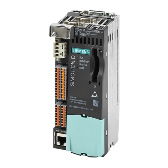
Page 18: Simotion D410-2 Dp Representation
Description 1.4 SIMOTION D410-2 DP representation SIMOTION D410-2 DP representation View The following figure shows a SIMOTION D410-2 DP with the interfaces and front elements. Figure 1-4 Location of interfaces and front elements for SIMOTION D410-2 DP SIMOTION D410-2 Manual, 02/2012... -
Page 19: Type Plates
Description 1.5 Type plates The interface to the power module (PM) is located at the rear of the SIMOTION D410-2. Figure 1-5 Power Module Interface (PM-IF) See also Interfaces (Page 33) Type plates The following figure shows all the information that the type plate on the module rear side contains. -
Page 20: Compactflash Card
CompactFlash card must be ordered as a separate component; it is not included in the SIMOTION D410-2 scope of supply. The SIMOTION Kernel (SIMOTION D410-2 firmware) and the software used to control the drives (SINAMICS firmware) are contained on the CompactFlash card. - Page 21 A maximum of seven different Z options are printed on the type plate of the CompactFlash card. When there are more than seven different Z options, the text "Z = see delivery order" is printed on the CompactFlash card in place of the Z option. SIMOTION D410-2 Manual, 02/2012...
- Page 22 Description 1.6 CompactFlash card Available Z options / licenses The following Z options are available for SIMOTION D410-2: Table 1- 5 Z options / licenses available for the SIMOTION D410-2 Designation Z option / license Example TControl Txx - TControl license and number...
-
Page 23: Licensing
SIMOTION D410-2 is a compact control unit predestined for single-axis applications. SIMOTION D410-2 has an integrated drive control for either a servo, a vector or a V/f axis. One real axis can be used without requiring a license for a SIMOTION D410-2. Speed- controlled axes and virtual axes never require a license. -
Page 24: Safety Information
The CompactFlash card may only be unplugged and plugged in when SIMOTION D410-2 is switched off (zero current)! The SIMOTION D410-2 is in a de-energized state when all the LEDs are OFF. The CompactFlash card is an ESD-sensitive component. When removing and inserting the CompactFlash card, observe the ESD regulations. -
Page 25: Operator Control (Hardware)
Operator control (hardware) Overview of operator control and display elements The following figure shows the arrangement of the operator control and display elements on the SIMOTION D410-2. Figure 2-1 SIMOTION D410-2 control and display elements SIMOTION D410-2 Manual, 02/2012... -
Page 26: Operator Controls
The following table shows the possible positions of the Service selector switch. The Service selector switch positions are explained in the order in which they are arranged on the SIMOTION D410-2. The service functions can generally be used in any set operating mode. SIMOTION D410-2... -
Page 27: Mode Selector Switch
DIAG button, see Section DIAG button (Page 29). 2.2.2 Mode selector switch Layout SIMOTION D410-2 provides a mode selector switch (PLC) behind the blanking cover in the lower area of the front panel. Figure 2-3 Mode selector switch, switch position "0"... - Page 28 Hardware Installation Manual. Note In the "RUN" setting, you can also control the SIMOTION D410-2 operating mode from the SIMOTION SCOUT engineering system. This means that it is not necessary to adjust the mode selector switch to change the operating mode.
-
Page 29: Diag Button
Operating Instructions. 2.2.3 DIAG button Layout The DIAG button is located on the SIMOTION D410-2 behind the blanking cover on the front. Figure 2-4 DIAG button Function The diagnostic data and non-volatile SIMOTION data is backed up on the CompactFlash card via the DIAG button. -
Page 30: Reset Button
The entire system is reset when the RESET button is pressed and a new power-up of the system forced. 2.2.5 Switch S5.0 Layout SIMOTION D410-2 provides the S5.0 switch behind the blanking cover in the lower area of the front panel. Figure 2-6 Switch S5.0 Function The DIP switch is used for switching the analog input (X131 connector) as voltage or current input. -
Page 31: Simotion Compactflash Card
The CompactFlash card may only be inserted or removed while the module is in a de- energized state. The SIMOTION D410-2 is in a de-energized state when all the LEDs are OFF. The CompactFlash card of the SIMOTION D410-2 must not be used in a SIMOTION D410, D4x5 or D4x5-2! Additional information... -
Page 32: Error And Status Displays
This table describes the LEDs and their meaning. Table 2- 4 Error and status displays Meaning Status indicator of the SINAMICS Integrated RUN/STOP SIMOTION D410-2 operating states OUT>5V Encoder current supply > 5 V (TTL/HTL) SF/BF: Group error / bus fault Additional information You can perform a detailed diagnosis with a PG/PC and the engineering system. -
Page 33: Interfaces
Interfaces Overview of interfaces This chapter describes the SIMOTION D410-2 DP interfaces. The arrangement of the interfaces on the module can be found in the SIMOTION D410-2 DP representation (Page 18) chapter. Available interfaces Table 3- 1 Overview of the available SIMOTION D410-2 DP interfaces... -
Page 34: Drive-Cliq Interface
Reserved, do not use Receive data - Reserved, do not use Reserved, do not use + (24 V) Power supply M (0 V) Electronic ground Signal type: I = Input; O = Output; VO = Voltage Output SIMOTION D410-2 Manual, 02/2012... - Page 35 Interfaces 3.2 DRIVE-CLiQ interface Connectable devices The following table contains the components that can communicate with SIMOTION D410-2 via the DRIVE-CLiQ interface. Note the max. number of nodes that can be connected to the DRIVE-CLiQ! Note SINAMICS S120 Note also the topology rules of the SINAMICS S120, see Function Manual, Section "Rules for wiring with DRIVE-CLiQ".
-
Page 36: Profibus Dp Interfaces
● Manual PROFIBUS DP interfaces Properties SIMOTION D410-2 DP provides two interfaces for connection on the PROFIBUS DP: ● PROFIBUS DP/MPI interface (X21) ● PROFIBUS DP interface (X24) The interfaces can be run asynchronously or isochronously, equidistant. SIMOTION D410-2 DP includes master and I-slave functionality. - Page 37 2XRS_DP RS-485 differential signal Reserved, do not use The 1P5 voltage is provided exclusively for the bus terminal. No OLPs are permitted. Signal type: VO = Voltage output (power supply); O = Output; B = Bidirectional SIMOTION D410-2 Manual, 02/2012...
-
Page 38: Encoder Interface (Htl/Ttl/Ssi)
HTL encoder). Operating a 5 V encoder on a 24 V supply may cause its electronic components to be destroyed. This setting can be set in the expert list of the drive in parameter p400 and in the following parameters. SIMOTION D410-2 Manual, 02/2012... - Page 39 For Pin 6 / Pin 9: At an encoder supply of 5 V, the voltage drops on the encoder supply cables are recorded and compensated by means of the sense cables. For this purpose, the sensor supply is corrected on the SIMOTION D410-2. NOTICE The KTY temperature sensor must be connected with the correct polarity.
- Page 40 This results in different switching thresholds. NOTICE Prefabricated cable for 5 V - TTL encoder If a 5 V - TTL encoder (6FX encoder) is used, the connecting cable 6FX8002-2CR00-... must be used. SIMOTION D410-2 Manual, 02/2012...
-
Page 41: Digital I/Os / Temperature Sensor / Analog Input
Digital I/Os / temperature sensor / analog input 3.5.1 Properties The onboard I/Os (Onboard I/Os) of the SIMOTION D410-2 are assigned to the SINAMICS Integrated. An appropriate configuration allows the I/Os also to be used by SIMOTION. Digital I/Os The digital I/Os at the X120, X121 and X130, X131 connectors are provided for the connection of sensors and actuators. -
Page 42: Interface Characteristics
DI 17- / EP M3 terminal (Enable Pulses) F-DI 1 DI 18 Fail-safe digital input 1 or digital inputs 18 and 19 DI 19+ DI 19- F-DI 2 DI 20 Fail-safe digital input 2 or digital inputs 20 SIMOTION D410-2 Manual, 02/2012... - Page 43 • Communication Interface Board (CIB) Extended functions Control takes place via the 2-channel F-DI of the SIMOTION D410-2: F-DI 0 ... F-DI 2 (X120.3...11) A fail-safe digital input is made up of 2 digital inputs. If SIMOTION D410-2 is mounted separately (PM340 connected to SIMOTION D410-2 via CUA31/32), use of the Safety Integrated Extended Functions via the on-board terminals (F-DI, F-DO) is not possible.
- Page 44 The use of the digital inputs (DI 0 ... DI 3) requires terminal M2 be connected. This is achieved by: • Also routing the ground reference of the digital inputs, or • A jumper to terminal M. This removes the electrical isolation for these digital inputs. SIMOTION D410-2 Manual, 02/2012...
- Page 45 An open input is interpreted as "low". Note If M1 or M2 is connected with M, the electrical isolation no longer exists. Note The fail-safe digital output (DO 16+, DO 16-) switches off retentively in the event of a short- circuit. SIMOTION D410-2 Manual, 02/2012...
- Page 46 If a digital output is parameterized and the external 24 V power supply is not connected (or the level is too low), the A03506 warning will be issued. This warning can also parameterized as a fault. See also Connection examples (Page 49) SIMOTION D410-2 Manual, 02/2012...
-
Page 47: Use Of The Interfaces
Use of the interfaces Fail-safe digital I/Os (F-DI/F-DO) The SIMOTION D410-2 provides three fail-safe isolated digital inputs (F-DI) and one fail-safe isolated digital output (F-DO): ● An F-DI consists of a digital input and a second digital input to which the cathode of the optocoupler is connected. - Page 48 • If the digital outputs DO 8 to DO 15 are in use, the power supply needs to be connected to X124. • The power module provides the electronics power supply of the SIMOTION D410-2. If the SIMOTION D410-2 needs to remain functional when the power module is switched off, X124 must be used for the electronics power supply.
-
Page 49: Connection Examples
Interfaces 3.5 Digital I/Os / temperature sensor / analog input 3.5.5 Connection examples Connection examples without a safety function Figure 3-1 SIMOTION D410-2 DP connection example SIMOTION D410-2 Manual, 02/2012... - Page 50 Interfaces 3.5 Digital I/Os / temperature sensor / analog input Figure 3-2 Example of circuits for the DI/DO without a safety function SIMOTION D410-2 Manual, 02/2012...
- Page 51 Interfaces 3.5 Digital I/Os / temperature sensor / analog input Figure 3-3 Internal connections of the SIMOTION D410-2 DP without a safety function SIMOTION D410-2 Manual, 02/2012...
- Page 52 Interfaces 3.5 Digital I/Os / temperature sensor / analog input Connection examples with Safety Integrated extended functions Figure 3-4 Internal connections of the SIMOTION D410-2 DP with a safety function SIMOTION D410-2 Manual, 02/2012...
- Page 53 Interfaces 3.5 Digital I/Os / temperature sensor / analog input 24 V1 Figure 3-5 Example of circuits for the F-DI/F-DO with a safety function SIMOTION D410-2 Manual, 02/2012...
-
Page 54: Power Supply
0.5 to 0.6 Nm Max. current carrying capacity incl. loop- 20 A through Max. cable length 10 m Interface assignment Table 3- 20 Power supply X124 Representation Terminal Designation Electronic power supply Electronic power supply Electronic ground Electronic ground SIMOTION D410-2 Manual, 02/2012... -
Page 55: Ethernet Interface
Ethernet interface Properties SIMOTION D410-2 has an X127 interface for connection to Industrial Ethernet. Industrial Ethernet is a communication network with a transmission rate of 10/100 Mbit/s. SIMOTION D410-2 offers the following functions via the Ethernet interface: ● PROFINET basic services (e.g. DCP, LLDP, SNMP) - Page 56 Ethernet receive differential signal Reserved, do not use Reserved, do not use Input Ethernet receive differential signal Reserved, do not use Reserved, do not use Note The MAC address is on a printed label visible from the front. SIMOTION D410-2 Manual, 02/2012...
-
Page 57: Measuring Sockets
Load current max. 3 mA Sustained short-circuit proof Reference potential is M terminal Interface assignment Table 3- 24 Interface assignments T0, T1 and T2 Representation Designation Measuring socket 0 Measuring socket 1 Measuring socket 2 Ground SIMOTION D410-2 Manual, 02/2012... -
Page 58: Power Module Interface
The test sockets are provided as a support to commissioning and diagnostics; they must not be connected for normal operation. Power Module Interface SIMOTION D410-2 can be connected to a SINAMICS S120 PM340 blocksize power module via the power module interface. Figure 3-6... -
Page 59: Technical Data
4000 m. 4000 m. Biological environmental conditions Class 2B1 according to Class 1B1 according to EN 60721-3-2 EN 60721-3-1 Chemically active environmental Class 2C2 according to Class 1C2 according to conditions EN 60721-3-2 EN 60721-3-1 SIMOTION D410-2 Manual, 02/2012... -
Page 60: Mechanical And Climatic Ambient Conditions
Conditions of use SIMOTION D410-2 is designed for use in stationary, weather-protected locations. SIMOTION D410-2 meets the conditions of use for Class 3C3 in accordance with DIN EN 60721-3-3 (operating locations with high traffic densities and in the immediate vicinity of industrial equipment with chemical emissions). - Page 61 SINAMICS S120 for AC Drives Manual. Vibration reduction If SIMOTION D410-2 is subjected to larger shocks or vibrations, you must use suitable measures to reduce the acceleration or the amplitude. We recommend installation on shock-absorbing material (e.g. rubber-metal vibration dampers).
-
Page 62: System Data, Connection Values, Dimensions And Weight
Technical data 4.3 System data, connection values, dimensions and weight System data, connection values, dimensions and weight General technical data The SIMOTION D410-2 has an integrated fan. Table 4- 3 General technical data Dimensions and weight Dimensions W x H x D 73 x 186.8 x 74.2 mm... -
Page 63: Interfaces And Performance Features
Interfaces and performance features 4.4.1 PLC and motion control performance Number of axes and clock cycles Table 4- 7 Maximum number of axes and minimum cycles for SIMOTION D410-2 PLC and motion control performance Maximum number of axes 8 axes Minimum PROFIBUS cycle 0.5 ms PROFIBUS Integrated... -
Page 64: Communication
Permanent process image for BackgroundTask (I/O variables) 64 bytes Additional configurable process image for each cyclic task (I/O variables) Address space for each PROFIBUS DP station 244 bytes Address space per SINAMICS Integrated (PROFIBUS 512 bytes Integrated) SIMOTION D410-2 Manual, 02/2012... -
Page 65: Onboard I/Os
Current consumption typical at 1 signal level 5 mA at 24 V Input delay, typ. (hardware): 0 → 1 signal 5 μs • • 1 → 0 signal 50 μs • • Measuring input, resolution 1 μs Measuring input, reproducibility 5 μs SIMOTION D410-2 Manual, 02/2012... - Page 66 Short circuit, ground fault and overload proof The digital inputs are protected against polarity reversal up to -30 V Reference potential for DI 16, DI 18, DI 20 and DO 16 is terminal M1 (X120, X130) SIMOTION D410-2 Manual, 02/2012...
-
Page 67: Onboard Encoder Interface
Technical data of the encoder interface Encoder interface TTL or HTL incremental encoders (with adjustable • parameters) Absolute encoder • Power supply 24 VDC / 0.35 A or 5 VDC / 0.35 A Short-circuit and overload proof Limit frequency 500 kHz SIMOTION D410-2 Manual, 02/2012... -
Page 68: Clock
Default setting when delivered DT#1992-01-01-00:00:00 Maximum deviation per day ±5 s for supply voltage switched on and switched off at 0° to 55° C Backup time At least 5 days (at 0 to 55° C) Charging time SIMOTION D410-2 Manual, 02/2012... - Page 69 (excluding software clock). The buffer is recharged in the POWER ON state. If the real-time clock backup time is exceeded, the time is reset. If the SIMOTION D410-2 is reset to its factory settings, the clock is also reset to the "default setting when delivered".
- Page 70 Technical data 4.5 Clock SIMOTION D410-2 Manual, 02/2012...
-
Page 71: Dimension Drawings
Dimension drawings SIMOTION D410-2 DP dimension drawing Figure 5-1 SIMOTION D410-2 DP dimension drawing SIMOTION D410-2 Manual, 02/2012... -
Page 72: Mounting Plate Dimension Drawing
Dimension drawings 5.2 Mounting plate dimension drawing Mounting plate dimension drawing Figure 5-2 Mounting plate dimension drawing SIMOTION D410-2 Manual, 02/2012... -
Page 73: Cad Data, Dimension Drawings, And Circuit-Diagram Macros
● In the DT Configurator of the Industry Mall (http://www.siemens.com/dt-configurator). Circuit-diagram macros EPLAN circuit-diagram macros are available for the SIMOTION D410-2. The macros are supported when you create circuit diagrams. For information on how to do this, refer to: Internet address (http://support.automation.siemens.com/WW/view/en/31622426). - Page 74 Dimension drawings 5.3 CAD data, dimension drawings, and circuit-diagram macros SIMOTION D410-2 Manual, 02/2012...
-
Page 75: Spare Parts / Accessories
Spare parts / accessories Available spare parts and accessories Table 6- 1 Spare parts and accessories Parts for SIMOTION D410-2 Order number Accessories Spare part CompactFlash card (CF card) 6AU1400-1PA22-0AA0 Blanking cover for the protection of the operator controls 6SL3064-3BB00-0AA0... - Page 76 Catalog. Note SIMOTION D410- The procedure for replacing the SIMOTION D410-2 fan is described in the Commissioning and Hardware Installation Manual. Spares on Web Spares On Web is an information system that enables you to find out which spare parts are available for your device.
-
Page 77: Tm31 Terminal Module
Temperature sensor input (KTY84-130 or PTC) CAUTION The 50 mm clearances above and below the component must be observed. Additional references SIMOTION D410-2 For further information on the TM31 terminal module, see the Commissioning and Hardware Installation Manual. SIMOTION D410-2... -
Page 78: Tm41 Terminal Module
60715 mounting rail. The TM54F offers safe digital I/Os for control of Safety Integrated functions of SINAMICS. A SIMOTION D410-2 can be assigned exactly one TM54F, which is connected via DRIVE- CLiQ. The TM54F terminal module is an alternative to using Safety Integrated functions via the onboard terminals (F-DI, F-DO) or via PROFIsafe. - Page 79 The 50 mm clearances above and below the component must be observed. Additional references SINAMICS S120 You find detailed information about the TM54F terminal module in the Safety Integrated Function Manual. See also DRIVE-CLiQ interface (Page 34) SIMOTION D410-2 Manual, 02/2012...
-
Page 80: Tm15 And Tm17 High Feature Terminal Modules
(gate function). Due to their high accuracy, the digital I/O channels of the TM17 High Feature are non-isolated. Note CAUTION The 50 mm clearances above and below the components must be observed. SIMOTION D410-2 Manual, 02/2012... -
Page 81: Cua31/Cua32 Control Unit Adapter
The 50 mm clearances above and below the component must be observed. The ventilation openings may not be covered by connecting cables. Additional references You will find more information on the CUA31/CUA32 control unit adapter in the SINAMICS S120 AC Drive Manual. SIMOTION D410-2 Manual, 02/2012... -
Page 82: Dmc20/Dme20 Drive-Cliq Hub
DRIVE-CLiQ link and therefore the data exchange. The DMC20/DME20 is also used with a SIMOTION D410-2 DP when a second encoder is required. As an SMx sensor module and a motor with DRIVE-CLiQ interface only have one DRIVE-CLiQ interface, a DMC20/DME20 must be used for a second encoder via DRIVE- CLiQ. -
Page 83: Standards And Approvals
Shielded Cables Shielded cables must be used with this equipment to maintain compliance with FCC regulations. SIMOTION D410-2 Manual, 02/2012... - Page 84 There is a risk of injury or of damage to assets. In hazardous areas, personal injury or damage to assets can occur if plug-in connections are disconnected during operation. Make sure that your system is always de-energized before disconnecting plug-in connections in hazardous areas. SIMOTION D410-2 Manual, 02/2012...
-
Page 85: Device-Specific Information
It is essential to follow the installation instructions in the SINAMICS S120 Manuals in order to ensure compliance with emitted interference and immunity values. The same installation instructions apply for the SIMOTION D410-2 control unit as for the SINAMICS S120 CU310-2 control unit with regard to EMC. - Page 86 5. Release of environmental pollutants or emissions as a result of improper operation of the system and/or failure to dispose of components safely and correctly SIMOTION D410-2 Manual, 02/2012...
-
Page 87: Esd Guidelines
Any damage that occurs to a module as a result of overvoltage is generally not recognized immediately and only comes to light after the equipment has been operating for some time. SIMOTION D410-2 Manual, 02/2012... -
Page 88: Electrostatic Charging Of Individuals
This figure indicates the maximum electrostatic charges that can accumulate on an operator when he comes into contact with the indicated materials. These values comply with the specifications in IEC 801-2. Figure B-2 Electrostatic voltage that can accumulate on operating personnel SIMOTION D410-2 Manual, 02/2012... -
Page 89: Basic Measures For Protection Against Discharge Of Static Electricity
If you have to take measurements on a module, make sure that you first discharge any static that may have accumulated in your body. To do this, touch a grounded metal object. Only use grounded measuring instruments. SIMOTION D410-2 Manual, 02/2012... - Page 90 ESD guidelines B.3 Basic measures for protection against discharge of static electricity SIMOTION D410-2 Manual, 02/2012...
-
Page 91: Index
Fail-safe, 47 TM15 DI/DO, 80 Technical data, 65 TM17 High Feature, 80 Dimension drawing, 73 TM31, 77 Mounting plate, 72 TM41, 78 SIMOTION D410-2 DP, 71 TM54F, 78 Dimensions, 62 Address space, 64 Display elements, 25 Ambient conditions DMC20 Climatic, 60... - Page 92 Index PLC and motion control SIMOTION D410-2 DP performance, 63 Interface assignment PROFIBUS DP interface X120, 42 Assignment, 37 X121, 44 X130, 45 X131, 46 Interfaces Analog input (X131), 41 Real-time clock, 68 Digital I/Os, 41 References, 4 DRIVE-CLiQ (X100), 34...
- Page 93 Index CompactFlash card, 21 SIMOTION D410-2, 19 UL certification, 83 Weight, 62 SIMOTION D410-2 Manual, 02/2012...
- Page 94 Index SIMOTION D410-2 Manual, 02/2012...
Need help?
Do you have a question about the SIMOTION D410-2 and is the answer not in the manual?
Questions and answers