SMA MEDIUM VOLTAGE POWER STATION 500SC-JP System Manual
Hide thumbs
Also See for MEDIUM VOLTAGE POWER STATION 500SC-JP:
- Transportation and installation requirements (38 pages)

Related Manuals for SMA MEDIUM VOLTAGE POWER STATION 500SC-JP


Summary of Contents for SMA MEDIUM VOLTAGE POWER STATION 500SC-JP
- Page 1 System Manual MEDIUM VOLTAGE POWER STATION 500SC-JP / 630SC-JP / 800SC-JP / 1000SC-JP / 1250SC-JP / 1600SC-JP MVPS22JP-SH-en-11 | 101817-00.01 | Version 1.1 ENGLISH...
- Page 2 The information contained in these documents is property of SMA Solar Technology AG. Any publication, whether in whole or in part, requires prior written approval by SMA Solar Technology AG. Internal reproduction used solely for the purpose of product evaluation or other proper use is allowed and does not require prior approval.
-
Page 3: Table Of Contents
Table of Contents SMA Solar Technology AG Table of Contents Information on this Document ..................... 12 Validity ................................12 Target Group ..............................12 Additional Information............................12 Symbols................................12 Typographies ..............................13 Nomenclature ..............................13 Safety............................. 14 Intended Use..............................14 Safety Information ............................15 Personal Protective Equipment......................... - Page 4 Table of Contents SMA Solar Technology AG Requirements for Transport and Mounting ..................... 41 4.2.1 Requirements and Ambient Conditions......................41 4.2.2 Center of Gravity Marker ..........................41 Transporting the MV Power Station Using a Crane ..................41 Transporting the MV Power Station by Truck, Train and Ship............... 42 Removing the Supplied Mounting Material from the MV Power Station............
- Page 5 Table of Contents SMA Solar Technology AG Visual Inspection and Mechanical Test......................74 6.3.1 Sequence for Visual Inspection and Mechanical Test ................... 74 6.3.2 MV Power Station ............................74 6.3.2.1 Checking the Grounding..........................74 6.3.2.2 Checking the High-Current Contacts Made at the Factory................75 6.3.2.3...
- Page 6 Table of Contents SMA Solar Technology AG 6.5.13.1 Selecting the Language ........................... 90 6.5.13.2 Setting the Date, Time and Time Zone ......................91 6.5.13.3 Entering the Operator Name.......................... 91 6.5.13.4 Changing the Password for the User Groups ....................91 6.5.14 Configuring System Settings via XML File.......................
- Page 7 Table of Contents SMA Solar Technology AG 8.3.4 Downloading Operating Data via HTTP Download..................109 8.3.4.1 Downloading Data in XML Format ......................... 109 8.3.4.2 Downloading Data in CSV Format ......................... 109 8.3.5 Saving Operating Data on a Memory Card....................110 8.3.5.1 Information on Saving Data on a Memory Card ..................110 8.3.5.2...
- Page 8 Table of Contents SMA Solar Technology AG 10.2.2.4 Medium-Voltage Switchgear........................... 136 10.2.2.5 Station Subdistribution............................. 136 10.2.3 Maintenance Work Every 24 Months ......................136 10.2.3.1 Station Subdistribution............................. 136 10.2.3.2 Medium-Voltage Switchgear........................... 136 10.2.3.3 Low-Voltage Meter (GSE) ..........................136 10.2.3.4 Sunny Central..............................137 10.2.4...
- Page 9 Table of Contents SMA Solar Technology AG 12.4.1.1 Overview of the Base Plates on the MV Power Station ................167 12.4.1.2 Inserting Cables through the Base Plates of the Inverters ................167 12.4.1.3 Inserting the Cables through the Base Plates of the Medium-Voltage Switchgear........168 12.4.1.4 Inserting the Cables through the Cable Glands ....................
- Page 10 Table of Contents SMA Solar Technology AG 13.3.2.1 No Active Power Limitation: Off Mode ......................191 13.3.2.2 Active Power Limitation with Setpoint Command via Modbus Protocol: WCtlCom Mode ......191 13.3.2.3 Active Power Limitation with Absolute Value: WCnst Mode ................ 191 13.3.2.4 Active Power Limitation as a Percentage of Nominal Power: WCnstNom Mode ........
- Page 11 Table of Contents SMA Solar Technology AG 14.1.2.1 Instantaneous Values............................218 14.1.2.2 Internal Device Values............................. 218 14.1.2.3 Status Values..............................219 14.1.3 Sunny String-Monitor ............................219 14.1.3.1 Instantaneous Values............................219 14.1.3.2 Internal Device Values............................. 219 14.1.3.3 Status Values..............................219 14.1.4 Zone Monitoring ..............................219 14.1.4.1 Instantaneous Values............................
-
Page 12: Information On This Document
This document is valid for the following device types of the MV Power Station with the inverters of the series Sunny Central 500CP-JP / 630CP-JP / 800CP-JP: • Medium Voltage Power Station 500SC-JP (MVPS 500SC-JP) • Medium Voltage Power Station 630SC-JP (MVPS 630SC-JP) • Medium Voltage Power Station 800SC-JP (MVPS 800SC-JP) •... -
Page 13: Typographies
1 Information on this Document SMA Solar Technology AG Typographies Typographies Example bold • Display messages • Set parameter WGra to 0.2. • Elements on a user interface • Terminals • Slots • Elements to be selected • Elements to be entered >... -
Page 14: Safety
Alterations to the product, e.g. changes or modifications, are only permitted with the express written permission of SMA Solar Technology AG. Unauthorized alterations will void guarantee and warranty claims and in most cases terminate the operating license. SMA Solar Technology AG shall not be held liable for any damage caused by such changes. -
Page 15: Safety Information
2 Safety SMA Solar Technology AG Safety Information This section contains safety information that must be observed at all times when working on or with the product. To prevent personal injury or property damage and to ensure long-term operation of the product, read this section carefully and observe all safety information at all times. - Page 16 2 Safety SMA Solar Technology AG Danger to life from electric shock even if the inverter is disconnected on the AC and DC sides The precharge unit of the order option "Q at Night" will carry live voltage even if the AC contactor and the DC switchgear are open.
- Page 17 2 Safety SMA Solar Technology AG Danger to life from electric shock when entering the PV field Ground-fault monitoring does not provide protection from personal injury. PV modules which are grounded with ground-fault monitoring discharge voltage to ground. Entering the PV field can result in lethal electric shocks.
-
Page 18: Personal Protective Equipment
2 Safety SMA Solar Technology AG Risk of injury from collapse of roof and protection roofs under excessive snow load If the maximum permissible snow load is exceeded, the roof and the protection roofs of the product may collapse or snap. -
Page 19: Product Overview
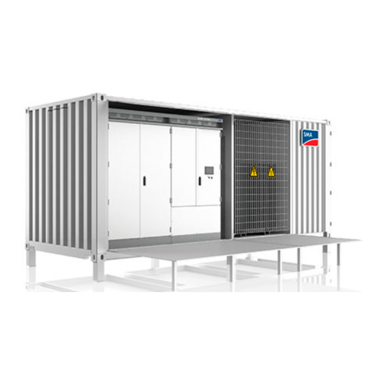
3 Product Overview SMA Solar Technology AG 3 Product Overview System Overview The MV Power Station is a complete solution for PV power plants. All devices required to convert the direct current generated by the PV modules into alternating current and to feed this current into the medium-voltage grid are located in the MV Power Station. -
Page 20: Design Of The Inverter
3 Product Overview SMA Solar Technology AG Position Designation Explanation MV transformer The MV transformer converts the inverter output voltage to the voltage level of the medium-voltage grid. Medium-voltage switchgear* The medium-voltage switchgear disconnects the MV trans- former from the medium-voltage grid. -
Page 21: Devices Of The Inverter
3 Product Overview SMA Solar Technology AG Devices of the Inverter Figure 4: Devices of the inverter Position Device Description Touch Display Different kinds of inverter data can be viewed on the touch display. The touch display is only used to view data. The display screen is activated by touching the touch display. -
Page 22: Devices Of The Mv Transformer
3 Product Overview SMA Solar Technology AG Devices of the MV Transformer The MV transformer is the link between the inverters and the medium-voltage grid. Figure 5: Devices of the MV transformer Position Device Description Contact thermometer or hermetic Temperature control unit or hermetic full-protection device... -
Page 23: Devices Of The Medium-Voltage Switchgear
3 Product Overview SMA Solar Technology AG Position Designation Station subdistribution Communit or control device*** * for order option "Ambient temperature up to +50°C/+55°C" ** for order option "spatial separation" *** for order option "Cascade control" Devices of the Medium-Voltage Switchgear The medium-voltage switchgear is used to disconnect the MV Power Station from the medium-voltage grid. -
Page 24: Devices Of The Station Subdistribution
3 Product Overview SMA Solar Technology AG Devices of the Station Subdistribution The station subdistribution is located in the compartment of the medium-voltage switchgear and contains the circuit breakers of the supply voltages and the optional devices. Depending on the order option of the MV Power Station, the number of lines and components is different in the station subdistribution. -
Page 25: Oil Tray
3 Product Overview SMA Solar Technology AG Position Designation Router Ethernet I/O Network 2 Network 1 3.10 Oil Tray The oil tray collects oil which can leak from the transformer under fault conditions. The oil separators integrated in the oil tray prevent the collected oil from leaking out of the oil tray in case the oil tray is full of rain water. The rain water is heavier than the oil and runs through the oil separator whereas the oil remains in the oil tray. -
Page 26: Transformer For Internal Power Supply
3 Product Overview SMA Solar Technology AG 3.11 Transformer for Internal Power Supply The transformer for internal power supply provides supply voltage for the inverters, Communit, lighting and outlet (see circuit diagram of the MV Power Station). Figure 11: Position of the transformer for internal power supply... -
Page 27: Operating And Display Elements
3 Product Overview SMA Solar Technology AG Position Designation Medium-voltage switchgear* AC Output Low-voltage transformer* Station subdistribution External communication terminal Communit* * optional 3.13 Operating and Display Elements 3.13.1 Switch in the Inverter 3.13.1.1 Key Switch The key switch is used to switch the inverter on and off. -
Page 28: Ac Disconnection Unit
3 Product Overview SMA Solar Technology AG 3.13.1.2 AC Disconnection Unit The AC disconnection unit disconnects the inverter from the MV transformer. Figure 14: Switch positions of the AC disconnection unit from ABB Position Designation Explanation Switch position on The AC disconnection unit is closed. -
Page 29: Switch In The Station Subdistribution
3 Product Overview SMA Solar Technology AG Position Designation ON button OFF button 3.13.2 Switch in the Station Subdistribution Reference designations are attached to the individual devices of the station subdistribution. Figure 16: Circuit breaker in the station subdistribution (example) -
Page 30: Switch On The Medium-Voltage Switchgear
3 Product Overview SMA Solar Technology AG 3.13.3 Switch on the Medium-Voltage Switchgear Figure 17: Control panels of the medium-voltage switchgear with circuit breaker in the transformer panel (example) Position Designation Grounding switch of the cable panel Load-break switch of the cable panel... -
Page 31: Touch Display
3 Product Overview SMA Solar Technology AG Position Designation USB port Automatic button to activate or deactivate the automatic function Confirmation button Serial interface RS232 Rotary switch to switch between on-site operation and remote operation 3.13.5 Touch Display 3.13.5.1 Design The touch display is used to display instantaneous values and parameter settings. - Page 32 3 Product Overview SMA Solar Technology AG Symbol Designation Explanation Bar chart Diagram 104: Representation of energy fed in during the last 14 days in kWh. DC side Representation of the instantaneous values • PV power in W • Insulation resistance in Ω...
- Page 33 3 Product Overview SMA Solar Technology AG Symbol Designation Explanation AC side Representation of the following instantaneous values: • Active power in W • Reactive power in VAr • Power frequency in Hz • AC current in A • AC voltage in V...
- Page 34 3 Product Overview SMA Solar Technology AG Symbol Designation Explanation Settings • Language selection • Brightness setting • Time setting • Format selection • Password entry Information • OS: version of the operating system • App.: version of the application software •...
-
Page 35: Leds Of The Sc-Com
3 Product Overview SMA Solar Technology AG 3.13.6 LEDs of the SC-COM 3.13.6.1 LEDs on the Enclosure Figure 20: LEDs on the enclosure LED designation Status Explanation POWER glowing green The SC-COM is supplied with voltage. The SC-COM is not supplied with voltage. -
Page 36: Leds On The Network Port
3 Product Overview SMA Solar Technology AG LED designation Status Explanation flashing green The SC-COM is communicating with the devices connected within the system. glowing green Internal communication has taken place in the last five minutes. glowing red An error has occurred in the internal communication. -
Page 37: Leds On The Optical Fiber Terminals
3 Product Overview SMA Solar Technology AG 3.13.6.3 LEDs on the Optical Fiber Terminals The SC-COM is also available with pre-wired optical fiber connections. If the optical fibers are connected to the splice box of the inverter, the status of the connection will be indicated by the LEDs of the SC-COM. -
Page 38: Tree View And Device View
3 Product Overview SMA Solar Technology AG Figure 23: Design of the user interface (example) Position Designation Tree view or device view Status bar Logout button Navigation bar Content area 3.13.7.2 Tree View and Device View You can call up data of the individual devices of your PV power plant in the tree view or the device view. Depending on which view you have selected, the devices are sorted differently. -
Page 39: Symbols On The Product
3 Product Overview SMA Solar Technology AG Symbol Explanation There is an error in the inverter. An error has occurred in the communication with the inverter. 3.14 Symbols on the Product The following gives an explanation of all the symbols found on the devices of the MV Power Station and on the type labels. -
Page 40: Transport And Mounting
4 Transport and Mounting SMA Solar Technology AG 4 Transport and Mounting Safety during Transport and Mounting Danger of crushing if raised or suspended loads tip over, fall or sway Vibrations or careless or hasty lifting and transportation may cause loads to tip over or fall. This can result in death or serious injury. -
Page 41: Requirements For Transport And Mounting
4 Transport and Mounting SMA Solar Technology AG Requirements for Transport and Mounting 4.2.1 Requirements and Ambient Conditions ☐ The maximum permissible gradient of the access road is 4%. ☐ During unloading, a distance of at least 2 m to neighboring obstacles must be observed. -
Page 42: Transporting The Mv Power Station By Truck, Train And Ship
4 Transport and Mounting SMA Solar Technology AG 7. Transport the MV Power Station to its final position as close to the ground as possible. 8. If the MV Power Station is to be transported directly to the mounting location and installed on the support surface, attach the support feet (see Section 4.6, page 43). -
Page 43: Attaching The Support Feet To The Mv Power Station
4 Transport and Mounting SMA Solar Technology AG Attaching the Support Feet to the MV Power Station The MV Power Station must be installed on the support surface with six support feet. The support feet for the station container can be found in the accessories kit in the medium-voltage switchgear compartment. The four outer support feet can be attached to the MV Power Station using the T-head bolts. - Page 44 4 Transport and Mounting SMA Solar Technology AG Figure 26: Dimensions of the support feet Position Designation Outside standard support foot with a height of 350 mm (adjustable height ±20 mm) Central standard support foot with a height of 350 mm (adjustable height ±20 mm) Outside support foot* with a height of 368 mm (non-adjustable height)
-
Page 45: Mounting The Mv Power Station
Mounting of the service platforms must be completed prior to commissioning. Hand rails for the service platforms of the MV Power Station The service platforms are provided by SMA Solar Technology AG. Local regulations for hand rails must be observed. Hand rails for the service platforms are not included in the scope of delivery of the MV Power Station and must be provided on-site. - Page 46 4 Transport and Mounting SMA Solar Technology AG Figure 27: Position of the support feet Requirements: ☐ The requirements for the foundation must be complied with (see "Information on Transport and Mounting of the MV Power Station"). ☐ The pea gravel ground and the mounting option must be prepared (see "Information on Transport and Mounting of the MV Power Station").
- Page 47 4 Transport and Mounting SMA Solar Technology AG Procedure: 1. Use a crane to set the oil tray down in the appropriate position so that it is aligned underneath the transformer compartment of the MV Power Station. Take the heavy weight of the oil tray into account.
- Page 48 4 Transport and Mounting SMA Solar Technology AG 9. Turn the locking mechanism of a platform to the vertical position so that the platform can be opened. Use a box wrench (width across flats: 22 mm). 10. Have at least two people pull the service platform forwards and down.
-
Page 49: Installation
5 Installation SMA Solar Technology AG 5 Installation Safety during Installation Danger to life from electric shock due to live voltage High voltages are present in the live components of the product. Touching live components results in death or serious injury due to electric shock. - Page 50 5 Installation SMA Solar Technology AG Danger to life from electric shock when entering the PV field Ground-fault monitoring does not provide protection from personal injury. PV modules which are grounded with ground-fault monitoring discharge voltage to ground. Entering the PV field can result in lethal electric shocks.
-
Page 51: Installation Sequence
Load-break switches or circuit breakers enable trouble-free DC-side disconnection of the inverter. Installation Sequence The sequence of installation work given in this section is recommended by SMA. It is important to begin the installation with the preparatory work and the grounding connection. Therefore, SMA recommends that you adhere to this sequence to avoid problems during installation. -
Page 52: Preparatory Work
5 Installation SMA Solar Technology AG Task Connecting the data cable of the Sunny String-Monitor Section 5.7.2.9, page 71 Connecting the DC cables for option "Busbar" Section 5.6.1, page 60 Connecting the DC cables for option "DC fuse" Section 5.6.2, page 62 Mounting the panels Section 12.3.1.2, page 164 Closing the base plate Section 5.8.1, page 71... -
Page 53: Opening The Drain Orifices In The Inverter Compartment
5 Installation SMA Solar Technology AG 5.3.1.3 Opening the Drain Orifices in the Inverter Compartment The drain orifices in the inverter compartment are sealed with plugs and must be opened prior to installation. Figure 28: Position of the drain orifices... -
Page 54: Removing The Transport Lock From The Mv Transformer Compartment
5 Installation SMA Solar Technology AG 8. Pull down the exhaust duct on both sides equally to the floor of the station. 9. Tighten the four screws on the exhaust duct. 10. Mount the panels on the inverter cabinet (see Section 12.3.1.2, page 164). -
Page 55: Working In The Compartment Of The Medium-Voltage Switchgear
5 Installation SMA Solar Technology AG Procedure: 1. Slightly loosen the screws of the lattice door in front of the MV transformer. 2. Unlock and open the lattice door. 3. Loosen the four tie-down straps. 4. Loosen the screws on the drain orifices in front of the MV transformer and remove the covers. -
Page 56: Removing The Desiccant Bags
5 Installation SMA Solar Technology AG 4. Remove the foils from the ventilation openings on the doors in the compartment of the medium-voltage switchgear: • Remove the grids on the inside of the doors. • Remove the foil from the ventilation openings. -
Page 57: Installing The Grounding On The Station Container
5 Installation SMA Solar Technology AG The battery must be charged when switching on the control device If the battery of the control device is empty, the control device and thus the medium voltage of the MV Power Station cannot be reconnected. -
Page 58: Installing The Ac Connection
5 Installation SMA Solar Technology AG Additionally required mounting material (not included in the scope of delivery): ☐ Ground electrode in accordance with the grounding concept of the PV system ☐ Clean cloth ☐ Ethanol cleaning agent ☐ Terminal lugs suitable for the selected cable cross-section ☐... -
Page 59: Installing The Ac Connection On The Mv Transformer
5 Installation SMA Solar Technology AG 5.5.2 Installing the AC Connection on the MV Transformer If the medium-voltage switchgear was not ordered with the MV Power Station, the AC cables must be connected to the MV transformer. The AC cables must be inserted through the base plate of the medium-voltage switchgear and through the partition to the MV transformer. -
Page 60: Installing The Dc Connection
5 Installation SMA Solar Technology AG Installing the DC Connection 5.6.1 Connecting the DC Cable to the Busbar Figure 32: Dimensions of the DC busbar (example) Position Designation Connection area DC+ Connection area DC‒ DC connection bracket with dimensions Terminal lug requirements: ☐... - Page 61 5 Installation SMA Solar Technology AG Torques of the power connections: Type of terminal lug Torque Tin-plated aluminum terminal lug on copper bar 37 Nm Tin-plated copper terminal lug on copper bar 60 Nm Additionally required mounting material (not included in the scope of delivery): ☐...
-
Page 62: Connecting The Dc Cables To The Connection Brackets
5 Installation SMA Solar Technology AG 5.6.2 Connecting the DC Cables to the Connection Brackets Figure 33: Connection area for DC fuses (example) Position Designation Connection area DC‒ Connection area DC+ DC connection bracket with dimensions Terminal lug requirements: ☐ Use tin-plated terminal lugs only. -
Page 63: Connecting The Cables For Communication, Control, Supply Voltage And Monitoring
5 Installation SMA Solar Technology AG Torques of the power connections: Type of terminal lug Torque Tin-plated aluminum or copper terminal lug on aluminum bar 37 Nm for M12 10 Nm for M8 Additionally required mounting material (not included in the scope of delivery): ☐... -
Page 64: Connecting The Network Cables
5 Installation SMA Solar Technology AG Damage to eyes and skin due to visible and invisible laser radiation The product contains class 1 LED or laser components in accordance with IEC 60825-1 (2003). The laser beam appears at the end of the optical fiber. Incorrect handling with laser beams can result in damage to eyes and skin. -
Page 65: Connecting The Cable In The Inverter
5 Installation SMA Solar Technology AG 5.7.2 Connecting the Cable in the Inverter 5.7.2.1 Connecting Optical Fibers with Subscriber Connector Figure 34: Position of the splice box Position Designation Splice box Additionally required mounting material (not included in the scope of delivery): ☐... - Page 66 5 Installation SMA Solar Technology AG 5. Insert the optical fibers from below through the cable gland into the splice box. 6. Mount the subscriber connectors on the optical fibers. 7. Plug the subscriber connectors into the SC-P plugs in the splice box.
-
Page 67: Connecting Optical Fibers Via Optical Fiber Pigtail
5 Installation SMA Solar Technology AG 5.7.2.2 Connecting Optical Fibers via Optical Fiber Pigtail Figure 35: Position of the splice box Position Designation Splice box Optical fiber requirements: ☐ The optical fiber cables must be equipped with a 50 μm multi-mode optical fiber. -
Page 68: Connecting The Network Cables
5 Installation SMA Solar Technology AG 5. Insert the optical fibers from below through the cable gland into the splice box. 6. Splice the optical fibers with the optical fiber pigtails in the splice box. 7. Plug the subscriber connectors into the SC-P plugs in the splice box. -
Page 69: Connecting Cables For Analog Setpoints
5 Installation SMA Solar Technology AG 4. Attach the network cables to the cable support rail using a cable tie. This will prevent the network cables from being pulled out inadvertently. 5. Mount the panels (see Section 12.3.1.2, page 164). 5.7.2.4 Connecting Cables for Analog Setpoints If the setpoints for active power limitation and reactive power control are not transmitted via the network, there are terminals in the inverter for connecting external setpoints. -
Page 70: Connecting The Cable For Remote Shutdown
5 Installation SMA Solar Technology AG 4. Secure the cables on the cable support rail. This will prevent the cables from being pulled out inadvertently. 5. Mount the panels (see Section 12.3.1.2, page 164). 5.7.2.6 Connecting the Cable for Remote Shutdown The remote shutdown enables the inverter to be switched off from a distance, e.g. from a control room. The function of the remote shutdown is similar to the stop function of the key switch. -
Page 71: Connecting The Data Cable Of The Sunny String-Monitor
5 Installation SMA Solar Technology AG 3. Connect the cables in accordance with the circuit diagram (see Section 12.6, page 175). 4. Secure the cables on the cable support rail. This will prevent the cables from being pulled out inadvertently. 5. Mount the panels (see Section 12.3.1.2, page 164). -
Page 72: Commissioning
6 Commissioning SMA Solar Technology AG 6 Commissioning Safety during Commissioning Danger to life from electric shock due to live voltage High voltages are present in the live components of the product. Touching live components results in death or serious injury due to electric shock. -
Page 73: Requirements For Commissioning
Statutory warranty and guarantee claims Statutory warranty or guarantee claims can only be asserted if commissioning was carried out by SMA Solar Technology AG or providing that the fully completed and signed "Commissioning Report for MV Power Station" is on file at SMA Solar Technology AG. Requirements for Commissioning General requirements: ☐... -
Page 74: Visual Inspection And Mechanical Test
6 Commissioning SMA Solar Technology AG ☐ SMA Solar Technology AG must have access to the safety documentation for the construction site. ☐ All system documentation such as cabling diagrams must be present. Visual Inspection and Mechanical Test 6.3.1 Sequence for Visual Inspection and Mechanical Test Procedure Ensure that the minimum clearances are complied with. -
Page 75: Checking The High-Current Contacts Made At The Factory
6 Commissioning SMA Solar Technology AG Procedure: 1. Ensure that all metal devices of the MV Power Station have been professionally connected to the grounding busbar (see circuit diagram of the MV Power Station). 2. Ensure that the grounding busbar has been professionally connected to the external grounding system. -
Page 76: Sunny Central
6 Commissioning SMA Solar Technology AG Test point Tasks High-current contact Check whether the high-current contacts established at the installation site are tightened to the correct torque. If the torque is not correct, release and clean the high-current contact and tighten with the required torque. -
Page 77: Adjusting The Transmission Ratio Of The Mv Transformer
6 Commissioning SMA Solar Technology AG Procedure Mount the protective covers. Section 12.3.1.1, page 163 Mount the panels. Section 12.3.1.2, page 164 Switch on the supply voltage and the AC disconnection unit. Section 6.4.7, page 78 6.4.2 Adjusting the Transmission Ratio of the MV Transformer Requirement: ☐... -
Page 78: Checking The Dc Voltage
6 Commissioning SMA Solar Technology AG 6.4.6 Checking the DC Voltage Danger to life due to electric arcs if measuring device is not connected correctly If the measurement points are incorrectly contacted, this can cause an electric arc. Electric arcs can result in death or serious injury. -
Page 79: Configuration
MV transformer. Contact your contact person at SMA Solar Technology AG to obtain the document "MVSG-Protection Relay Settings" in which the default settings and explanations are stated. The final settings of the protective device must be made upon agreement with the electric utility company. - Page 80 6 Commissioning SMA Solar Technology AG Procedure: 1. Set the protective device (see document "MVSG - Protection Relay Settings" and documentation of the medium- voltage switchgear). Observe the maximum current values on the medium-voltage side. Medium-voltage Grid voltage Current on the high-voltage side of the MV transformer in-...
-
Page 81: Configuring The Network Settings On The Computer
6 Commissioning SMA Solar Technology AG Medium-voltage Grid voltage Current on the high-voltage side of the MV transformer in- switchgear [kV] cluding 10% overload [A] 1000 kVA 1260 kVA 1600 kVA Manufacturer of the 24.94 25.46 32.09 40.74 medium-voltage 21.17 26.67 33.87 switchgear: Schneider... -
Page 82: Configuring The Inverter For A Static Network
6 Commissioning SMA Solar Technology AG Using a static IP address is recommended. You can select the IP address yourself. Use the address range which is available to your router. If necessary, refer to the router manual. If you are using a Power Plant Controller for the automatic control of your PV power plant, a dynamic IP address with DHCP is not possible. -
Page 83: Detecting New Devices
6 Commissioning SMA Solar Technology AG 6. If you would like to use the Modbus protocol, activate the box Use Modbus. 7. In the field Modbus port, enter the port to be used by the inverter when communicating via the Modbus protocol. -
Page 84: Setting The Frequency-Dependent Active Power Limitation
6 Commissioning SMA Solar Technology AG 6.5.7.2 Setting the Frequency-Dependent Active Power Limitation Parameter block Some parameters must only be changed in the operating state "Stop". The entry will not be accepted in any other operating state. Procedure: 1. Make sure the inverter is in the operating state "Stop". -
Page 85: Setting Reactive Power Control
6 Commissioning SMA Solar Technology AG 6.5.7.4 Setting Reactive Power Control Operation failure of the PV power plant due to incorrectly set parameters If the parameter settings for grid management services are incorrect, the PV power plant may not be able to meet the requirements of the grid operator. -
Page 86: Setting Grid Monitoring And Grid Limits
6 Commissioning SMA Solar Technology AG Avoiding electromagnetic interference emissions in large-scale PV systems To avoid electromagnetic interference emissions in large-scale PV systems at the changeover from night mode to feed-in operation, it is recommended using Modbus communication for setpoint in feed-in operation and night mode. -
Page 87: Activating The Manual Resume Mode
6 Commissioning SMA Solar Technology AG 6.5.8.3 Activating the Manual Resume Mode If the inverter is switched off due to a grid limit infringement, you can prevent an automatic restart of the inverter. Only once the error has been acknowledged will the inverter switch back on. You can activate the Manual Resume Mode for individual errors of grid limit infringement. -
Page 88: Setting The Medium Voltage
6 Commissioning SMA Solar Technology AG 6.5.9.3 Setting the Medium Voltage The line-to-line voltage of the overvoltage side of the MV transformer (parameter TrfVolExlHi) has to be adapted to the nominal conductor voltage of the utility grid (parameter VRtg). It is important that the transmission ratio of the external MV transformer is adjusted at the same time. -
Page 89: Redetecting The Sunny String-Monitors Via The Sunny Central String-Monitor Controller
6 Commissioning SMA Solar Technology AG Procedure: 1. Log into the user interface (see Section 12.8.1, page 177). 2. Select the tab Parameters. 3. Set the parameter DevFunc to AutoDetect_SSMU. 4. Select the button [Save]. 5. Select the tab Instantaneous values. 6. Select SSMUNoOf and check the number of detected Sunny String-Monitors. -
Page 90: Changing System Settings Via Touch Display
6 Commissioning SMA Solar Technology AG 6.5.12 Changing System Settings via Touch Display 6.5.12.1 Selecting the Language 1. Select 2. Select 3. Use the country symbol to select the language. 4. Confirm your entry by selecting 6.5.12.2 Setting the Date, Time and Time Zone Inverter adopts changes The inverter will adopt date, time or time zone changes made via the display. -
Page 91: Setting The Date, Time And Time Zone
6 Commissioning SMA Solar Technology AG 4. Select the button [Save]. 5. To log off from the user interface, select the button [Logout]. 6.5.13.2 Setting the Date, Time and Time Zone 1. Log into the user interface (see Section 12.8.1, page 177). -
Page 92: Configuring System Settings Via Xml File
6 Commissioning SMA Solar Technology AG 6.5.14 Configuring System Settings via XML File 6.5.14.1 Uploading the File custom.xml When you upload the file custom.xml to the user interface, the communication unit checks the file to ensure that the values entered are valid and accurate, and adopts the settings at the next reset of the communication unit. -
Page 93: Resetting The Communication Unit
6 Commissioning SMA Solar Technology AG No confirmation after deleting the file custom.xml If you perform the following steps, the file custom.xml will be deleted immediately without displaying a dialog box confirming the deletion. • Save the file custom.xml before deleting it. -
Page 94: Checking The Heating Elements And Hygrostat
6 Commissioning SMA Solar Technology AG Procedure: 1. Switch the inverter to Stop. 2. Connect the supply voltage (see Section 7.9.1, page 103). ☑ The fans start to run for a few moments. ✖ The fans do not start up? • Contact Service partner. -
Page 95: Switching The Inverter On
6 Commissioning SMA Solar Technology AG Risk of burns due to hot components Some components of the product can get very hot during operation. Touching these components can cause burns. • Observe the warnings on all components. • During operation, do not touch any components marked with such warnings. -
Page 96: Disconnecting And Reconnecting
7 Disconnecting and Reconnecting SMA Solar Technology AG 7 Disconnecting and Reconnecting Safety When Disconnecting and Reconnecting Voltage Sources Danger to life due to applied voltages High voltages are present in the live components of the product. Touching live components results in death or serious injury due to electric shock. - Page 97 7 Disconnecting and Reconnecting SMA Solar Technology AG Danger to life due to applied voltages as a result of automatic reconnection If the automatic cascade control is activated, it is possible that the voltage is automatically reconnected when working on the medium-voltage switchgear. Touching live components can result in death or serious injury due to electric shock.
-
Page 98: Connection Point Overview
7 Disconnecting and Reconnecting SMA Solar Technology AG Connection Point Overview 7.2.1 Power Connection Points Figure 38: Overview of the power connection points Position Designation DC subdistribution, e.g. Sunny String-Monitor DC main distribution, e.g. Sunny Main Box Cabinet Inverter MV transformer Medium-voltage switchgear Higher-level medium-voltage switchgear (string, ring or transfer station) -
Page 99: Connection Points For Supply Voltage
7 Disconnecting and Reconnecting SMA Solar Technology AG 7.2.2 Connection Points for Supply Voltage Figure 39: Connection points for supply voltage Position Designation Transformer for internal power supply Station subdistribution Lighting Outlet Inverter Communit Transformer circuit breaker Circuit breaker of the entire station subdistribution... -
Page 100: Disconnecting The Inverter
7 Disconnecting and Reconnecting SMA Solar Technology AG Disconnecting the Inverter 7.4.1 Switching off the Inverter 1. Turn the key switch to Stop. 2. Remove the key. This will protect the inverter from inadvertent reconnection. 3. Wait 15 minutes before opening the doors. This allows the inverter capacitors to discharge. -
Page 101: Disconnecting The Mv Transformer
7 Disconnecting and Reconnecting SMA Solar Technology AG 2. If the supply voltage is also to be disconnected downstream from the supply voltage circuit breaker, switch the external circuit breaker of the supply voltage off. Tip: The external circuit breaker of the supply voltage is usually located in a subordinate distribution station. -
Page 102: Reconnecting The Mv Power Station
7 Disconnecting and Reconnecting SMA Solar Technology AG Depending on how the PV power plant is designed, the automatic reconnection function has to be deactivated in the superordinate MV Power Station with order option "Cascade control". Procedure: 1. Disconnect the inverter (see Section 7.4, page 100). -
Page 103: Reconnecting The Inverter
7 Disconnecting and Reconnecting SMA Solar Technology AG Connect and disconnect the AC voltage of the MV transformer Only a duly authorized person is allowed to connect and disconnect the AC voltage of the MV transformer. Procedure: 1. Unground (see documentation for the medium-voltage switchgear). -
Page 104: Reconnecting The Ac Side
7 Disconnecting and Reconnecting SMA Solar Technology AG 7.9.2 Reconnecting the AC Side 1. Reconnect the supply voltage and external voltages (see Section 7.9.1, page 103). 2. Reconnect the AC voltage of the MV transformer (see Section 7.8, page 102). 3. Switch on the AC disconnection unit in the inverter. -
Page 105: Operation
8 Operation SMA Solar Technology AG 8 Operation The information in the following sections affect the inverters only. Information on the operation of further optional devices of the MV Power Station, such as the medium-voltage switchgear or the control device for cascade control, can be found in the documentation of the respective device. -
Page 106: Displaying The Operation Data Via Sunny Portal
8 Operation SMA Solar Technology AG 8.2.2 Displaying the Operation Data via Sunny Portal 8.2.2.1 Registering the Inverter in Sunny Portal Automatic PV system identifier In general, you do not have to change the preset number in the field PV system identifier. Sunny Portal uses this number to uniquely identify the PV power plant. -
Page 107: Saving Operating Data
8 Operation SMA Solar Technology AG Procedure: 1. Log into the user interface as an installer (see Section 12.8.1, page 177). 2. Select Sunny Central > Info. 3. Select the button [Delete] in the field Sunny Portal Buffer Load. Saving Operating Data 8.3.1 Reducing Storage Capacity by Averaging The communication unit can average the data over a defined time period. -
Page 108: Accessing The Ftp Server Via The Web Browser
8 Operation SMA Solar Technology AG Option Explanation Read only You have read access rights only on the integrated FTP server. The integrated FTP server is deactivated. 4. Select the button [Save]. 8.3.3.2 Accessing the FTP Server via the Web Browser You can log into the FTP server of the communication unit as either "user"... -
Page 109: Downloading Operating Data Via Http Download
8 Operation SMA Solar Technology AG • Repeat the FTP connection test. • If an error occurs, contact your network administrator. 10. Select the button [Save]. 8.3.4 Downloading Operating Data via HTTP Download 8.3.4.1 Downloading Data in XML Format You can download the data collected by the communication unit via HTTP download. This function enables manual download of your collected PV system data in CSV or XML format to your computer. -
Page 110: Saving Operating Data On A Memory Card
8 Operation SMA Solar Technology AG Option Explanation LF (Unix/Linux) Control character used in Linux to separate lines in a CSV file. CR (Mac) Control character used in Macintosh to separate lines in a CSV file. 8. In the field Separator character , select the separator character to be used to separate content within the CSV file. -
Page 111: Inserting The Memory Card
8 Operation SMA Solar Technology AG 8.3.5.2 Inserting the Memory Card Danger to life due to electric shock or electric arc if live components are touched • Switch off the inverter and wait at least 15 minutes before opening it to allow the capacitors to discharge completely. -
Page 112: Update Via User Interface
8 Operation SMA Solar Technology AG Requirement: ☐ Connection to Sunny Portal must be established (see Section 8.2.2, page 106). Procedure: 1. Log into the user interface (see Section 12.8.1, page 177). 2. Select Sunny Central > Settings > Data transmission. 3. In the field Automatic firmware update, select the option yes. -
Page 113: Switching To Grounded Operation
8 Operation SMA Solar Technology AG 5. Turn the key switch to Start. ☑ The insulation monitoring device starts collecting data. If the parameter IsoErrIgn is set to On, the error 3504 ‒ Insulation failure ignored is displayed. ✖ After 15 minutes, the displayed error 3504 does not disappear? The insulation is defective. -
Page 114: Deleting The Device Description
8 Operation SMA Solar Technology AG Deleting the Device Description Whenever you replace a device in your PV power plant, the descriptions of the existing devices need to be deleted so that the communication unit is able to detect new devices. -
Page 115: Troubleshooting
9 Troubleshooting SMA Solar Technology AG 9 Troubleshooting Safety during Troubleshooting Danger to life from electric shock due to high voltages on the product High voltages can be present on the product under fault conditions. Touching live components results in death or serious injury due to electric shock. - Page 116 9 Troubleshooting SMA Solar Technology AG Error Cause and corrective measure The transformer for internal The transformer circuit breaker has tripped. power supply does not sup- Corrective measures: ply voltage. • Ensure that the nominal current on the primary side of the transformer for internal power supply is correctly set.
- Page 117 9 Troubleshooting SMA Solar Technology AG Error Cause and corrective measure The fans do not start up. The required temperature has not been reached. Corrective measures: • To check the function of the fans, turn down the thermostat. ☑ The fans start up.
-
Page 118: Troubleshooting In The Inverter
9 Troubleshooting SMA Solar Technology AG Error Cause and corrective measure The MV transformer cannot The MV transformer is defective. be reconnected. Corrective measures: • Replace the MV transformer. Contact the Service (see Section 17, page 256). There is air in the MV transformer. -
Page 119: Reading Off Disturbance Messages
9 Troubleshooting SMA Solar Technology AG 6. In the field E-mail when, select the desired event type for which the e-mail is to be sent. 7. Enter the required data in the fields Mail server (SMTP), Sender e-mail, User name and Password. -
Page 120: Acknowledging Disturbance Messages
9 Troubleshooting SMA Solar Technology AG • Select the button [Download]. • Choose the save location. • Select the button [Save]. 9.3.3 Acknowledging Disturbance Messages 9.3.3.1 Acknowledging Disturbance Messages via the Key Switch Dealing with disturbances Disturbance messages should only be acknowledged once the underlying causes have been eliminated. - Page 121 9 Troubleshooting SMA Solar Technology AG • Waiting for acknowledgement The inverter switches to the operating state "Disturbance" and opens the AC contactor and DC switchgear. The inverter does not feed in until the disturbance is acknowledged. Once the disturbance has been acknowledged, it is no longer shown on the touch display. The inverter then checks whether the cause of the disturbance has been rectified.
-
Page 122: Explanation Of The Error Tables
9 Troubleshooting SMA Solar Technology AG 9.3.4.2 Explanation of the Error Tables You will find the following information in the error tables in the following sections: Error no. Explanation Corrective measures 1301 Left-hand rotating magnetic field 30 s ‒ • Check phase position. - Page 123 9 Troubleshooting SMA Solar Technology AG Error no. Explanation Inverter behavior Corrective measures 0404* Frequency change per second too 30 s 30 s ‒ ‒ high for grid operation 0502* Power frequency is too low. Power 30 s 30 s ‒ • Check power frequency.
- Page 124 9 Troubleshooting SMA Solar Technology AG After a grid failure, the inverter monitors the utility grid for a specific period before reconnecting. When the inverter monitors the utility grid after a grid error, the grid monitoring time is complied with. Certain errors, such as grid errors, cause the inverter to shut down.
-
Page 125: Error Numbers 34Xx To 40Xx - Disturbance On The Pv Array
9 Troubleshooting SMA Solar Technology AG Error no. Explanation Inverter behavior Corrective measures 1301 Left-hand rotating magnetic field is 30 s ‒ • Check phase position. connected. • Make sure all fuses are switched on. 1500 The conditions for grid reconnec- ‒... - Page 126 9 Troubleshooting SMA Solar Technology AG Error no. Explanation Inverter behavior Corrective measures 3601 Leakage current to ground has oc- ‒ • Check the grounding and equipotential curred in the PV array or the bonding. threshold defined in parameter • Check the module wiring and system RisoCtlWarn has been reached.
-
Page 127: Error Numbers 6Xx To 9Xx - Disturbance On The Inverter
9 Troubleshooting SMA Solar Technology AG Error no. Explanation Inverter behavior Corrective measures 3512 The Remote GFDI has detected a ‒ • Check the PV array for ground faults. permanent ground fault. 3515 A ground fault detected by ‒ • Check the PV array for ground faults. - Page 128 9 Troubleshooting SMA Solar Technology AG Error no. Explanation Inverter behavior Corrective measures 6119 Data structure for communication 5 min 5 min x • Contact Service partner. between operation control unit and digital signal processor is in- valid. 6120 Watchdog tripping error 30 s...
- Page 129 9 Troubleshooting SMA Solar Technology AG Error no. Explanation Inverter behavior Corrective measures 6452 Measured AC voltage of the utility ‒ • Contact Service partner. grid is less than inverter voltage. 6453 AC voltage of grid limit monitoring ‒ • Contact Service partner.
- Page 130 9 Troubleshooting SMA Solar Technology AG Error no. Explanation Inverter behavior Corrective measures 7600 Communication between touch dis- ‒ • Check cabling between touch display play and communication unit is in- and communication unit. terrupted. The error number ap- • Contact Service partner.
-
Page 131: Displaying Disturbance Messages For Active Power Limitation
9 Troubleshooting SMA Solar Technology AG Error no. Explanation Inverter behavior Corrective measures 8702 Several digital active power set- ‒ • Contact Service partner. points are available. 8703 Power factor of the external reac- ‒ • Contact Service partner. tive power setpoint is invalid. -
Page 132: Displaying Disturbance Messages For The Reactive Power Setpoint
9 Troubleshooting SMA Solar Technology AG Display Cause and corrective measures AnInFail The mode WCnstNomAnIn has been selected and the value measured at the analog in- put is less than 2 mA. Corrective measures: • Make sure the cable is correctly connected to the analog input. -
Page 133: Maintenance
In particular, cleaning work and corrosion protection may be necessary more frequently. If the MV Power Station is installed in a desert region, the maintenance intervals must be reduced. SMA recommends to check the function of the devices in the MV Power Station after each sandstorm. -
Page 134: Maintenance Work Every 12 Months
10 Maintenance SMA Solar Technology AG Consumables and maintenance materials Only those consumables and maintenance materials not normally included in the standard equipment of an electrically qualified person are listed. It is taken for granted that standard tools and materials such as torque wrenches, one-contact voltage testers and wrenches will be available for all maintenance operations. -
Page 135: Mv Transformer
10 Maintenance SMA Solar Technology AG Task Check the function of the fans with order option "+50°C/+55°C". Make sure that the grounding contacts are securely in place and show no discoloration or corrosion. Check the function of the doors and hinges and lubricate them. -
Page 136: Medium-Voltage Switchgear
10 Maintenance SMA Solar Technology AG 10.2.2.4 Medium-Voltage Switchgear Task Carry out the visual inspection of the general condition (cleanliness, no corrosion, etc.). If re- ‒ quired, clean the enclosure and repair corroded surfaces. Check the accessory for completeness and its current state. -
Page 137: Sunny Central
10 Maintenance SMA Solar Technology AG 10.2.3.4 Sunny Central Required maintenance materials and tools: ☐ A suitable water-free, heat-resistant lubricant ☐ A testing device approved by the manufacturer of the AC disconnection unit, e.g. TT1 by ABB ☐ Talcum, petroleum jelly or wax for maintaining the seals ☐... -
Page 138: Maintenance Work Every 6 Years
SF6 gas holders. voltage switchgear Check the MV transformer for operating noise. ‒ Contact the SMA Service Line after each short circuit. ‒ Prior to each use of the outlet, check the residual-current device in the station sub- ‒... -
Page 139: Oil Tray
10 Maintenance SMA Solar Technology AG 10.2.6.2 Oil Tray Task Regularly check the oil tray for leakages. If necessary, eliminate leakages. Regularly check the oil tray for dirt contamination. Clean if necessary. Regularly check the oil separator for dirt contamination. Clean if necessary. -
Page 140: Repairs Every 10 Years
10 Maintenance SMA Solar Technology AG 10.3.4 Repairs every 10 Years Inverter Task Comment Replace 24 V power supply units • Contact the Service. Replace the fans of the AC disconnection unit • Contact the Service. Replace exterior key switch, front element and label •... -
Page 141: Cleaning The Interior
If visual defects are present, repair these immediately. 5. Check the welded joints on the devices for damage. Contact the SMA Service Line if any welded joints are damaged. 6. Check whether the type label of the MV Power Station is present, complete and legible. -
Page 142: Checking The Latches, Door Stops And Hinges
10 Maintenance SMA Solar Technology AG Position Designation Door Frame construction Required maintenance material (not included in the scope of delivery): ☐ A suitable water-free, heat-resistant lubricant ☐ Talcum, petroleum jelly or wax for maintaining the seals Danger to life due to electric shock or electric arc if live components are touched If the MV Power Station and its devices are not correctly disconnected, dangerous voltages may be present in the... -
Page 143: Checking The Inverter Surface
10 Maintenance SMA Solar Technology AG 3. Check whether the door hinges move easily. If the door hinges do not move easily, apply lubricant. 4. Lubricate all moving parts and movement points. 5. Tighten any loose screws with the appropriate torque. -
Page 144: Maintenance Work On The Inverter
10 Maintenance SMA Solar Technology AG • Paint the entire surface. 10.5 Maintenance Work on the Inverter 10.5.1 Analyzing the Temperature Indicators Depending on the type of inverter bridge, the inverter cabinet contains 8 or 17 temperature indicators which monitor the temperature of the inverter bridges. - Page 145 The interactive protocol "Temperature Indicators Analysis Protocol" can be downloaded at www.SMA-Solar.com. Danger to life due to electric shock or electric arc if live components are touched •...
-
Page 146: Cleaning The Air Duct And Ventilation Grids
10 Maintenance SMA Solar Technology AG 10.5.2 Cleaning the Air Duct and Ventilation Grids Danger to life due to electric shock or electric arc if live components are touched If the MV Power Station and its devices are not correctly disconnected, dangerous voltages may be present in the components which, if touched, will result in death or serious injury. -
Page 147: Checking The Fuses/Disconnection Blades
10 Maintenance SMA Solar Technology AG 5. Slide the ventilation plate into the inverter cabinet. The ventilation grid in the ventilation plate must face the rear panel. ☑ The ventilation grid ends up flush with the inverter. ✖ The ventilation plate will not go all the way in? •... -
Page 148: Checking The Surge Arresters
10 Maintenance SMA Solar Technology AG Damage to bolted connections through overtightening If the permitted torques are exceeded, bolted connections can be damaged. In this case, fault-free operation of the inverter is no longer ensured. • Only tighten loose bolted connections to the prescribed torque. Torque specifications are indicated in the circuit diagram of the inverter. -
Page 149: Checking The Fans
10 Maintenance SMA Solar Technology AG Danger to life due to electric shock or electric arc if live components are touched If the MV Power Station and its devices are not correctly disconnected, dangerous voltages may be present in the components which, if touched, will result in death or serious injury. -
Page 150: Checking The Labels
10 Maintenance SMA Solar Technology AG 10.5.8 Checking the Labels Labels on the inverter Figure 44: Position of the labels on the inverter Position Order number Designation 86-029687 Use hearing protection 86-05200 Beware of dangerous voltage 86-79615 Beware of a danger zone... - Page 151 10 Maintenance SMA Solar Technology AG Position Order number Designation 86-10867153 Risk of electrical shock even when the device is disconnected. 86-003307 5 Safety rules 86-003314 Risk of lethal electric shock due to active power source 86-1086701025 Danger of burn injury due to hot fuses below the cover.
-
Page 152: Checking The Heating Elements And Hygrostat
10 Maintenance SMA Solar Technology AG Danger to life due to electric shock or electric arc if live components are touched If the MV Power Station and its devices are not correctly disconnected, dangerous voltages may be present in the components which, if touched, will result in death or serious injury. -
Page 153: Checking The Function Of The Ups
10 Maintenance SMA Solar Technology AG Risk of burns due to hot components Some components of the product can get very hot during operation. Touching these components can cause burns. • Observe the warnings on all components. • During operation, do not touch any components marked with such warnings. -
Page 154: Checking The Ac Disconnection Unit
10 Maintenance SMA Solar Technology AG Danger to life due to electric shock or electric arc if live components are touched If the MV Power Station and its devices are not correctly disconnected, dangerous voltages may be present in the components which, if touched, will result in death or serious injury. - Page 155 10 Maintenance SMA Solar Technology AG Figure 48: Switch positions of the AC disconnection unit from ABB Position Designation Explanation Switch position on The AC disconnection unit is closed. Central switch position The AC disconnection unit was tripped and is open.
-
Page 156: Checking The Dc Switchgear
10 Maintenance SMA Solar Technology AG 10.5.12 Checking the DC switchgear Figure 49: Indicators on the DC load-break switch Position Designation Spring status indicator Position indicator ON button OFF button Requirements: ☐ Supply voltage must be present. Danger to life from electric shock due to live voltage High voltages are present in the conductive components of the inverter. - Page 157 10 Maintenance SMA Solar Technology AG 5. Switch the inverter to Start. 6. Open the doors of the interface cabinet. 7. Check whether the DC load-break switch is switched on and indicating the position On. If the DC load-break switch is not switched on or not indicating the position On, contact (see Section 17 "Contact", page 256).
-
Page 158: Disposal
11 Disposal SMA Solar Technology AG 11 Disposal Proper disposal A MV Power Station which has come to the end of their service life constitute electronic waste. Electronic waste contains on the one hand valuable materials (e.g. copper, aluminum or steel) which can be recycled as secondary raw materials, and on the other, substances which are hazardous to the environment (e.g. -
Page 159: Periodic Actions
12 Periodic Actions SMA Solar Technology AG 12 Periodic Actions 12.1 Opening and Closing the Doors of the Station Container Figure 50: Elements of the station container doors Position Designation Locking mechanism Sealing mechanism Door handle Unlocking the doors of the station container To access the medium-voltage switchgear and the Communit or the rear sides of the inverter or to perform maintenance work, you must unlock and open the doors of the station container. - Page 160 12 Periodic Actions SMA Solar Technology AG 2. Pull the right-hand door handle up and out. 3. Release the two sealing mechanisms on the left-hand door handle. Turn the sealing mechanisms clockwise. 4. Pull the left-hand door handle up and out.
- Page 161 12 Periodic Actions SMA Solar Technology AG Locking the doors of the station container 1. Release and close the doors. 2. Press the left-hand door handle in towards the door and press down. 3. Lock the two sealing mechanisms on the left-hand door handle.
-
Page 162: Setting Up The Service Platform At The Medium-Voltage Switchgear Compartment
12 Periodic Actions SMA Solar Technology AG 12.2 Setting up the Service Platform at the Medium-Voltage Switchgear Compartment For all work in the medium-voltage switchgear compartment, the service platform must be mounted in front of the medium-voltage switchgear compartment. Risk of injury if heavy service platforms are lowered too fast The service platforms of the MV Power Station are very heavy. -
Page 163: Mounting And Disassembly Work
12 Periodic Actions SMA Solar Technology AG 12.3 Mounting and Disassembly Work 12.3.1 Mounting and Disassembly Work in the Inverter 12.3.1.1 Disassembling and Mounting the Protective Covers Figure 51: Position of the protective covers Position Designation Protective cover Danger to life due to electric shock or electric arc if live components are touched •... -
Page 164: Disassembling And Mounting The Panels
12 Periodic Actions SMA Solar Technology AG Mounting the protective covers 1. Tighten all protective covers (torque: 5 Nm). 2. Ensure that the protective covers are firmly in place. 12.3.1.2 Disassembling and Mounting the Panels Danger to life due to electric shock or electric arc if live components are touched •... -
Page 165: Disassembling And Mounting The Ventilation Grids
12 Periodic Actions SMA Solar Technology AG 12.3.1.3 Disassembling and Mounting the Ventilation Grids Disassembling the ventilation grids 1. Release the screws of the right-hand ventilation grid. (head size:-T40). 2. Pull the lower side of the right-hand ventilation grid forwards to remove it. -
Page 166: Mounting And Disassembly Work In The Medium-Voltage Switchgear
12 Periodic Actions SMA Solar Technology AG 2. Screw the left-hand ventilation grid on (torque: 20 Nm,-head size T40). 3. Insert the right-hand ventilation grid. 4. Screw the right-hand ventilation grid on (torque: 20 Nm,-head size T40). 12.3.2 Mounting and Disassembly Work in the Medium-Voltage Switchgear 12.3.2.1 Disassembling and Mounting the Kick Plates... -
Page 167: Cable Entry
12 Periodic Actions SMA Solar Technology AG 12.4 Cable Entry 12.4.1 Inserting the Cables through the Base Plates 12.4.1.1 Overview of the Base Plates on the MV Power Station The MV Power Station is fitted with base plates through which the cables are inserted. The cables should be protected between the foundation and the MV Power Station. -
Page 168: Inserting The Cables Through The Base Plates Of The Medium-Voltage Switchgear
12 Periodic Actions SMA Solar Technology AG 3. Unscrew and remove all parts of the base plate underneath the connection area of the inverter. This will give you enough room for inserting the cables. 4. Lead all cables for the connection in the inverter through the opening. Make sure that the data cables are routed separately from the power cables. -
Page 169: Inserting The Cables In The Communit
12 Periodic Actions SMA Solar Technology AG Requirements: ☐ The doors of the medium-voltage compartment must be open (see Section 12.1, page 159). ☐ The service platform in front of the medium-voltage compartment must be installed (see Section 12.2, page 162). Procedure: 1. Remove the base plate with the cable glands. This will give you enough room for inserting the cables. - Page 170 12 Periodic Actions SMA Solar Technology AG Unused cable glands Do not remove the filler plugs of the unused cable glands. The filler plugs serve as seals for the product. Property damage due to dust intrusion and moisture penetration Dust or moisture intrusion can damage the product and impair its functionality.
-
Page 171: Inserting The Cables
12 Periodic Actions SMA Solar Technology AG 12.4.3 Inserting the Cables 1. Remove the screws at the top of the sealing plate. 2. Remove the sealing plate. 3. Loosen the screws at the side of the sealing plate. 4. Remove the required number of rubber seals from the sealing plate. Make sure that the diameter of the rubber seals corresponds to the diameter of the cables to be inserted. -
Page 172: Bolted Connections
12 Periodic Actions SMA Solar Technology AG 12.5 Bolted Connections 12.5.1 Preparing the Grounding and DC Cables for Connection Connection overview with one two-hole terminal lug for grounding and DC cables Figure 54: Design of the connection with one two-hole terminal lug... - Page 173 12 Periodic Actions SMA Solar Technology AG Connection overview with one one-hole terminal lug for grounding and DC cables Figure 55: Design of the connection with one one-hole terminal lug Position Designation Nut M12 or M8 Spring washer (29 mm for M12 or 18 mm for M8) Fender washer (32 mm for M12 or 20 mm for M8)
- Page 174 12 Periodic Actions SMA Solar Technology AG Connection overview with two two-hole terminal lugs for DC cables Figure 56: Design of the connection with two two-hole terminal lugs Position Designation Nut M12 Spring washer (29 mm) Fender washer (32 mm) Tin-plated two-hole terminal lugs...
-
Page 175: Clamp Connections
12 Periodic Actions SMA Solar Technology AG Connection overview with two one-hole terminal lugs for DC cables Figure 57: Design of the connection with two one-hole terminal lugs Position Designation Nut M12 or M8 Spring washer (29 mm for M12 or 18 mm for M8) Fender washer (32 mm for M12 or 20 mm for M8) - Page 176 12 Periodic Actions SMA Solar Technology AG 2. Strip the insulation of the insulated conductors. 3. Connect the cable in accordance with the circuit diagram. • Remove the connection plug from the base terminal. • Insert the screwdriver in the square opening of the connection plug.
-
Page 177: Connecting The Cable Shield Using A Shield Clamping Saddle
IP address: 192.168.100.2 Subnet mask: 255.255.255.0 Password for the user groups "installer" and "user": sma Identical passwords for the user groups If your "user" password is the same as your "installer" password, you will automatically be logged in as an installer. -
Page 178: Logging Out Of The User Interface
12 Periodic Actions SMA Solar Technology AG 3. Enter the IP address of the communication unit in the address bar and press the enter key. ☑ The user interface opens. 4. To change the language, select the desired language in the field Language. -
Page 179: Function Description
13 Function Description SMA Solar Technology AG 13 Function Description 13.1 Operating States 13.1.1 Overview of the Operating States Figure 58: General overview of the operating states of the inverter System Manual MVPS22JP-SH-en-11... -
Page 180: Stop
13 Function Description SMA Solar Technology AG 13.1.2 Stop The inverter is switched off. Stop, Fast stop or Remote shutdown active will appear on the touch display. If the key switch is set to Start, the inverter switches to the operating state "Grid monitoring". -
Page 181: Monitoring The Power Frequency
13 Function Description SMA Solar Technology AG Position Parameter Description ‒ Grid limit level 1 is breached, timer for B starts counting ‒ Grid limit level 2 is breached, timer for A starts counting ‒ Grid limit level 2 is breached for delay time level 2 → grid disconnec- tion ‒... -
Page 182: Startup
13 Function Description SMA Solar Technology AG 13.1.5 Startup 13.1.5.1 In Normal Operation: Active Power Ramp-Up The inverter works up to its maximum feed-in power via a ramp. This means that the inverter gradually increases the ratio of feed-in power per second by the value set in the parameter WGra. -
Page 183: Shutdown
13 Function Description SMA Solar Technology AG If the AC power generated by the inverter falls below 5 kW, the inverter switches from feed-in operation to "Q at Night" operation. The inverter feeds in reactive power in accordance with the parameter settings. Since this status can also occur during the day, the DC switchgear remains closed at first in order to avoid unnecessary switching cycles of the DC switchgear. -
Page 184: Remote Shutdown
13 Function Description SMA Solar Technology AG Tripping the fast stop The fast stop should only be tripped in case of imminent danger. Tripping of the fast stop does not entail fast discharge of the capacitors. If the inverter is to be switched off and properly shut down via an external signal, the remote shutdown input is to be used. -
Page 185: Grounding And Insulation Monitoring
13 Function Description SMA Solar Technology AG Unlike active islanding detection, with passive islanding detection the utility grid is not actively influenced, but simply passively monitored. This involves monitoring the speed of the frequency change. If the power frequency changes by a certain amount in a certain time, a stand-alone grid is detected and the inverter disconnects from the utility grid. -
Page 186: Remote Gfdi
13 Function Description SMA Solar Technology AG Figure 62: GFDI Position Designation GFDI 13.2.3.3 Remote GFDI Depending on the order option, ground fault monitoring in the inverter may be carried out via ground fault detection and interruption with motor drive, in short "Remote GFDI". This grounds one terminal of the PV array. Remote GFDI also enables automatic error processing. -
Page 187: Insulation Monitoring Device
13 Function Description SMA Solar Technology AG If the Remote GFDI trips, initially a temporary error will be assumed and a motor drive will close the Remote GFDI after a defined waiting time. No external switch command is required to close the tripped Remote GFDI. The inverter can switch back to feed-in operation after a waiting time. -
Page 188: Gfdi And Insulation Monitoring Device
13 Function Description SMA Solar Technology AG • If the parameter IsoErrIgn is set to On, the error message from the measuring circuit is ignored when the insulation resistance falls below the error threshold. The inverter continues to feed into the grid and generates the error message 3504 ‒ Insulation failure ignored. -
Page 189: Remote Gfdi And Insulation Monitoring Device
13 Function Description SMA Solar Technology AG The insulation monitoring device takes approximately five minutes to detect the correct insulation resistance. The value of the insulation resistance can be read off from the user interface in the instantaneous value Riso. If the insulation is intact, the inverter switches back to the operating state "MPP load operation."... -
Page 190: Power Control
13 Function Description SMA Solar Technology AG Insulation monitoring should be performed in the operating state "MPP load operation". This will ensure that all parts of the system are included in the insulation measurement. Insulation monitoring To disable the grounding of the PV array, the parameter RemMntSvc must be set to On. This will open the Remote GFDI by means of a motor drive. -
Page 191: Frequency-Independent Active Power Limitation
13 Function Description SMA Solar Technology AG power be increased again. In this case, the saved value P forfeits its validity. In addition, a minimum threshold for power frequency shortfall can be defined with the parameter P-HzStopMin, shown here at point D. If the power frequency falls below the grid limit, the inverter will shut down and switch to the operating state "Grid monitoring". -
Page 192: Active Power Limitation Via Standard Signal: Wcnstnomanin Mode
13 Function Description SMA Solar Technology AG 13.3.2.5 Active Power Limitation via Standard Signal: WCnstNomAnIn Mode The active power limitation is set via an analog signal at the input terminals for the setpoint. This is usually implemented by a ripple control signal. The electrical current strength of the connected signal determines the nominal active power. -
Page 193: Reactive Power Setpoint Via Standard Signal: Varcnstnomanin Mode
13 Function Description SMA Solar Technology AG 13.3.3.6 Reactive Power Setpoint via Standard Signal: VArCnstNomAnIn Mode The reactive power setpoint is set at the input terminals for the setpoints via an analog signal. This is usually implemented by a ripple control signal. The analog value is converted into a reactive power setpoint. The electrical current strength of the connected signal determines the setpoint. -
Page 194: Displacement Power Factor Cos Φ Via Standard Signal: Pfcnstanin Mode
13 Function Description SMA Solar Technology AG 13.3.3.8 Displacement Power Factor cos φ via Standard Signal: PFCnstAnIn Mode The reactive power setpoint is set at the input terminals for the setpoints via an analog signal. This is usually implemented by a ripple control signal. The analog value is converted into a displacement power factor cos φ. The electrical current strength of the connected signal determines the setpoint. -
Page 195: Displacement Power Factor Cos Φ As A Function Of Feed-In Power: Pfctlw Mode
13 Function Description SMA Solar Technology AG 13.3.3.9 Displacement Power Factor cos φ as a Function of Feed-In Power: PFCtlW Mode In the PFCtlW mode, the displacement power factor cos φ is set as a function of feed-in power. This dependency is depicted by a configurable characteristic curve. -
Page 196: Measures For Voltage Support Through Parameterization Of Reactive Power/Voltage Characteristic Curve: Varctlvolhystdb Mode
13 Function Description SMA Solar Technology AG The reactive power is set as a function of the grid voltage. The reactive power setpoint is adjusted in stages. Figure 70: Characteristic curve for reducing reactive power as a function of the grid voltage If the grid voltage is changed by the configurable voltage difference Q-VDif for the configurable duration of Q- VDifTm, the reactive power setpoint will be adjusted by the value Q‑VArGra. - Page 197 13 Function Description SMA Solar Technology AG By supplying reactive power, the inverter performs voltage-stabilizing measures in the event of overvoltage or undervoltage. The parameterization is carried out by means of a reactive power/voltage characteristic curve. The characteristic curve can be flexibly configured by parameterizing the slope, a type of deadband through two voltage points and a hysteresis.
- Page 198 13 Function Description SMA Solar Technology AG Figure 73: Characteristic curve for reducing reactive power with hysteresis Figure 74: Characteristic curve for reducing reactive power with deadband and hysteresis MVPS22JP-SH-en-11 System Manual...
-
Page 199: Measures For Voltage Support Through Parameterization Of Reactive Power/Voltage Characteristic Curve: Varctlvolhystdba Mode
13 Function Description SMA Solar Technology AG The parameter Q-VArTmsSpnt determines the delay time which must elapse before the calculated reactive power setpoint is actively used. In order to prevent mutual interference of several systems with this function, the parameter Q- VArTmsVtg can be used to set a delay time. -
Page 200: Q At Night
13 Function Description SMA Solar Technology AG In addition, the parameter Q-VLockInW can be used to define a voltage at which reactive power control will be activated after the time specified in parameter Q-VLockInTm has elapsed. If the voltage exceeds the threshold defined in parameter Q-VLockOutW, the reactive power control will be deactivated once the time specified in parameter Q-VLockOutTm has elapsed. -
Page 201: Q At Night Depending On The Grid Voltage: Varctlvol Mode
13 Function Description SMA Solar Technology AG The analog value is converted to a setpoint for power limitation. Here, the parameter QoDQmax is the end point of the linear characteristic curve. Figure 76: Limitation of the reactive power to the parameter QoDQmax 13.3.4.6 Q at Night Depending on the Grid Voltage: VArCtlVol Mode... -
Page 202: Measures For Voltage Support Through Parameterization Of Reactive Power/Voltage Characteristic Curve: Varctlvolhystdb Mode
13 Function Description SMA Solar Technology AG The reactive power is set as a function of the grid voltage. The reactive power setpoint is adjusted in stages. Figure 77: Characteristic curve for reducing reactive power as a function of the grid voltage If the grid voltage is changed by the configurable voltage difference Q-VDif for the configurable duration of Q- VDifTm, the reactive power setpoint will be adjusted by the value Q‑VArGra. - Page 203 13 Function Description SMA Solar Technology AG By supplying reactive power, the inverter performs voltage-stabilizing measures in the event of overvoltage or undervoltage. The parameterization is carried out by means of a reactive power/voltage characteristic curve. The characteristic curve can be flexibly configured by parameterizing the slope, a type of deadband through two voltage points and a hysteresis.
- Page 204 13 Function Description SMA Solar Technology AG Figure 80: Characteristic curve for reducing reactive power with hysteresis Figure 81: Characteristic curve for reducing reactive power with deadband and hysteresis The parameter Q-VArTmsSpnt determines the delay time which must elapse before the calculated reactive power setpoint is actively used.
-
Page 205: Measures For Voltage Support Through Parameterization Of Reactive Power/Voltage Characteristic Curve: Varctlvolhystdba Mode
13 Function Description SMA Solar Technology AG In order to prevent mutual interference of several systems with this function, the parameter Q-VArTmsVtg can be used to set a delay time. This delay time defines how long a voltage change must be pending before a change in reactive power feed-in is triggered. -
Page 206: Behavior In The Absence Of Active And Reactive Power Setpoints
13 Function Description SMA Solar Technology AG 13.3.5 Behavior in the Absence of Active and Reactive Power Setpoints In the event of failure of setpoints for active and reactive power control, the inverter is capable of bridging the gap in two ways: •... - Page 207 13 Function Description SMA Solar Technology AG Depending on the order option, the inverter may be equipped with a managed switch. Figure 83: System network of two inverters (example) Monitoring and control can be organized in two separate networks: • Monitoring network This network is used for monitoring, parameterization and remote diagnosis.
-
Page 208: Grid Management Services
13 Function Description SMA Solar Technology AG 13.5 Grid Management Services 13.5.1 Dynamic Grid Support (FRT) 13.5.1.1 Full and Limited Dynamic Grid Support (FRT) With dynamic grid support (Fault Ride Through ‒ FRT), the inverter supports the utility grid during a brief grid-voltage dip (Low Voltage Ride Through ‒... -
Page 209: Dynamic Undervoltage Detection
13 Function Description SMA Solar Technology AG Ratio V Inverter behavior grid 20% to 90% The ratio of grid voltage V to nominal voltage V is in the critical range. There is a distur- grid bance in the utility grid. -
Page 210: Grid Support In The Event Of Overvoltage (Hvrt)
13 Function Description SMA Solar Technology AG Position Parameter Description VCtllCharTm The delay time of the dynamic undervoltage detection defines the in- tersection of the continuous grid-limit function with the time axis. VCtllLimTm Delay time for grid limit level 1 The function of the dynamic undervoltage detection is activated via the parameter VCtllCharEna. -
Page 211: Cascade Control
13 Function Description SMA Solar Technology AG The tripping threshold is defined by the parameter FRTDbVolNomMax. 13.6 Cascade Control The order option "Cascade control" allows for staggered reconnection of several medium-voltage switchgears after a grid failure or maintenance work. For this option, the following changes are implemented by default: •... -
Page 212: Grid Protection
13 Function Description SMA Solar Technology AG 13.7 Grid Protection The order option "Grid protection" allows for voltage and frequency monitoring of the utility grid and disconnection of the inverter after a grid fault. This order option is independent of the grid monitoring function integrated in the inverter. -
Page 213: Zone Monitoring
13 Function Description SMA Solar Technology AG 13.9 Zone Monitoring The order option "Zone Monitoring" offers the possibility to monitor up to eight input currents of the inverter as standard, to detect fuse and string failures, and in this way, to minimize the power and yield losses. -
Page 214: Operating Data And Parameters
14 Operating Data and Parameters SMA Solar Technology AG 14 Operating Data and Parameters The information in the following sections affect the inverters only. Information on the operating data and parameters of further optional devices of the MV Power Station, such as the medium-voltage switchgear or the control device for cascade control, can be found in the documentation of the respective device. - Page 215 14 Operating Data and Parameters SMA Solar Technology AG Status messages of active power limitation Name Display Description P-WModStt No mode for active power limitation has been selected. WMax Active power is limited by specification of an upper limit. This limit is based on Pmax.
-
Page 216: Error Channels
14 Operating Data and Parameters SMA Solar Technology AG Status messages of the reactive power setpoint Name Display Description Q-VArModStt No mode for specifying the reactive power setpoint has been se- lected. VdcMax The reactive power is limited due to DC voltage being too high. -
Page 217: Measured Values
14 Operating Data and Parameters SMA Solar Technology AG 14.1.1.3 Measured Values Name Description Grid voltage in V Grid current in A AC power in kW Reactive power in kVAr Apparent power in kVA Power frequency in Hz PV voltage in V... -
Page 218: Service-Relevant Displays
14 Operating Data and Parameters SMA Solar Technology AG Name Description CntFanHs Operating hours of the heat sink fan, in h CntFanTrf1 Operating hours of the transformer fan 1, in h CntFanTrf2 Operating hours of the transformer fan 2, in h CntFanCab1 Operating hours of the interior fan 1, in h... -
Page 219: Status Values
14 Operating Data and Parameters SMA Solar Technology AG Name Description SysDt System date SysTm System time 14.1.2.3 Status Values Name Description Error Error detected by the Sunny Central String-Monitor Controller Mode Operating state of the Sunny Central String-Monitor Controller ParaCfg Error in parameterization of monitoring time detected... -
Page 220: Status Values
14 Operating Data and Parameters SMA Solar Technology AG 14.1.4.2 Status Values Name Values Description Mode Initialization Waiting Zone Monitoring is activated, but the minimum current for the evaluation is not yet reached. Operation Zone Monitoring is activated and the minimum current for the evaluation is reached. - Page 221 14 Operating Data and Parameters SMA Solar Technology AG Name Description Value/range Explanation Default value P-WMod** Mode for active power Limits active power to Pmax limitation WCtlCom Limits active power via an exter- nal control unit, such as the Power Reducer Box...
- Page 222 14 Operating Data and Parameters SMA Solar Technology AG Name Description Value/range Explanation Default value Qmax** Limitation of reactive 0 kVAr to 220 kVAr Sunny Central 500CP-JP 220 kVAr power 0 kVAr to 310 kVAr Sunny Central 630CP-JP 310 kVAr 0 kVAr to 385 kVAr Sunny Central 800CP-JP...
- Page 223 14 Operating Data and Parameters SMA Solar Technology AG Name Description Value/range Explanation Default value Q-VArMod** Mode for reactive power Sets reactive power to 0 kVAr control and displacement power factor cos φ to 1 VArCtlCom Specifies reactive power via ex- ternal control unit, such as the Power Reducer Box...
- Page 224 14 Operating Data and Parameters SMA Solar Technology AG Name Description Value/range Explanation Default value QoDQ- Reactive power setpoint Sets reactive power to 0 kVAr VArMod** in the operating mode and displacement power factor "Q at Night" cos φ to 1 VArCtlCom Specifies reactive power via ex- ternal control unit, such as the Power Reducer Box...
- Page 225 14 Operating Data and Parameters SMA Solar Technology AG Name Description Value/range Explanation Default value PF-PF Displacement power fac- 0.5 to 1 The parameter should not fall be- tor cos φ low 0.8 in normal operation. The lower limit is defined by the parameter PFAb- sMin.
- Page 226 14 Operating Data and Parameters SMA Solar Technology AG Name Description Value/range Explanation Default value PF-WLockTm Waiting time for activa- 0 s to 100 s ‒ 2 s tion or deactivation of the cos φ(P) characteris- tic curve Q-VDif** Definition of voltage 0.1% to 10% The value refers to the nominal change leading to a voltage VRtg.
- Page 227 14 Operating Data and Parameters SMA Solar Technology AG Name Description Value/range Explanation Default value WGraEna** Activation of the active Deactivated power change gradient Activated WGraRe- Activation of the decou- Deactivated conEna** pling protection ramp for Activated reconnection P-VtgGraNom Active power gradient 0.017%/s to...
- Page 228 14 Operating Data and Parameters SMA Solar Technology AG Name Description Value/range Explanation Default value P-WSubValRun Substitute value for ac- 0 kW to 1,000 kW Sunny Central 500CP-JP 500 kW tive power limitation in Sunny Central 630CP-JP 700 kW normal feed-in operation during communication Sunny Central 800CP-JP...
-
Page 229: Grid Monitoring And Grid Limits
14 Operating Data and Parameters SMA Solar Technology AG Name Description Value/range Explanation Default value PF-PFEx- Substitute value of the ex- OvExt Overexcited OvExt tSubValR citation type in normal UnExt Underexcited feed-in operation during communication distur- bance PwrMonEr- Mode used in the event... - Page 230 14 Operating Data and Parameters SMA Solar Technology AG Name Description Range Explanation Default value VCtllLimTm Delay time for undervolt- 0 ms - ‒ 1,000 ms age level 1 to 1,000,000 ms VCtlllLim Threshold for undervolt- 0% to 100% ‒ age release level 2 VCtlllLimTm Delay time for undervolt- 0 ms -...
- Page 231 14 Operating Data and Parameters SMA Solar Technology AG Name Description Range Explanation Default value HzCtllLim Threshold for underfre- 45 Hz to 50 Hz For 50 Hz grid 49 Hz quency level 1 55 Hz to 60 Hz For 60 Hz grid 58.8 Hz HzCtllLimTm Delay time for underfre- 0 ms - ‒ 1,000 ms quency level 1...
-
Page 232: Grid Support
14 Operating Data and Parameters SMA Solar Technology AG 14.2.1.3 Grid Support Name Description Value/range Explanation Default value FRTMod* Dynamic grid support op- FRT_BDEW Complete dynamic grid support FRT_BDEW erating modes FRT_Partial Limited dynamic grid support FRT_SDLWindV Complete dynamic grid support... -
Page 233: Insulation Monitoring
14 Operating Data and Parameters SMA Solar Technology AG 14.2.1.4 Insulation monitoring Name Description Value/range Explanation Default value IsoErrIgn* Ignore insulation error Deactivated Activated Error is only ignored when the in- verter is in feed-in operation. RemMntSvc PV array grounding is Deactivated deactivated. - Page 234 14 Operating Data and Parameters SMA Solar Technology AG Name Description Value/range Explanation Default value PVStrT Once the specified time 1 s to 300 s ‒ 90 s has elapsed, the inverter switches from the operat- ing state "Grid monitor- ing" to the operating state "Grid monitoring time reached".
- Page 235 14 Operating Data and Parameters SMA Solar Technology AG Name Description Value/range Explanation Default value CntRs* Meter reset h-Cnt Operating hours meter E-Cnt Energy meter CntFanHs All fan runtime meters CntFanCab2 Fan runtime meter CntHtCab2 Fan runtime meter Ofs_h-On** Offset for operating 0 h to 2,147,482 h ‒...
-
Page 236: Sunny Central String-Monitor Controller
14 Operating Data and Parameters SMA Solar Technology AG Name Description Value/range Explanation Default value ExlTrfErrEna Activation of hermetic Deactivated protection of MV trans- Activated former * To view or change this parameter, you must enter the installer password. ** To change this parameter, you must enter the installer password. -
Page 237: Sunny String-Monitor
14 Operating Data and Parameters SMA Solar Technology AG Name Description Value/range Explanation Default value ErrLevGr1* Sensitivity of error detection for 24 Sensitive 50 min ‒ 10% 32 Regular group 1 24 Regular 50 min ‒ 14% Parameter exists for all six groups 24 Insensitive 50 min ‒... - Page 238 14 Operating Data and Parameters SMA Solar Technology AG Name Description Value/range Explanation Default value SSM Identifier* Identification number of Sunny 1 to 99 ‒ String-Monitor Group String 1 Assigns strings to their respective 0 to 3 Parameter exists for all eight...
-
Page 239: Zone Monitoring
14 Operating Data and Parameters SMA Solar Technology AG Name Description Value/range Explanation Default value Surge Arrester1 Alarm contact (e.g. theft protec- Activ High Contact activated when volt- tion for Sunny String-Monitor) age is present Activ Low Contact activated when no... - Page 240 14 Operating Data and Parameters SMA Solar Technology AG Name Description Value/range Explanation Default value DevFunc Device function Default, no action ResetMeasuring Restarts the algorithm. All measured value are deleted. Factory Resets all parameters to default set- tings Ackn Acknowledge errors...
-
Page 241: Technical Data
15 Technical Data SMA Solar Technology AG 15 Technical Data 15.1 MV Power Station 500SC-JP DC Input MPP voltage range at +25°C 365 V to 600 V MPP voltage range at +50°C 332 V to 600 V Maximum input current 1400 A Number of independent MPP inputs... -
Page 242: Mv Power Station 630Sc-Jp
15 Technical Data SMA Solar Technology AG General Data Maximum operating altitude above mean sea level 1000 m Maximum operating altitude above MSL for option "In- 1001 m to 2000 m / 2001 m to 3000 m stallation at high altitudes" Fresh air consumption** 3,000 m³/h... -
Page 243: Mv Power Station 800Sc-Jp
15 Technical Data SMA Solar Technology AG General Data Width x height x depth 6058 mm x 2591 mm x 2438 mm Weight < 10 t Operating temperature range −25°C to +40°C / −25°C to +55°C* Self-consumption in operation** < 1900 W Standby consumption*** < 100 W + 600 W Internal auxiliary supply voltage 230 V / 400 V (3/N/PE), 50 Hz / 60 Hz... -
Page 244: Mv Power Station 1000Sc-Jp
15 Technical Data SMA Solar Technology AG AC Output Maximum total harmonic distortion < 3 % Maximum output current at 20 kV 26 A Transformer vector groups Dy11 / YNd11 Displacement power factor cos φ 0.9 overexcited to 0.9 underexcited * information based on inverter Efficiency Maximum efficiency 97.4 %... - Page 245 15 Technical Data SMA Solar Technology AG DC Input Number of independent MPP inputs Number of DC inputs AC Output AC power at +25°C* 1000 kVA AC power at +40°C* 946 kVA AC power at +50°C* 910 kVA Nominal AC voltage 20 kV Optional nominal voltages 10 kV to 33 kV...
-
Page 246: Mv Power Station 1250Sc-Jp
15 Technical Data SMA Solar Technology AG General Data Degree of protection of medium-voltage compartment as IP23D per IEC 60529 Degree of protection of transformer compartment and in- IP00 verter compartment as per IEC 60529 * optional ** information based on inverter *** separated according to consumption of the inverter and standby power losses of the transformer 15.5... -
Page 247: Mv Power Station 1600Sc-Jp
15 Technical Data SMA Solar Technology AG General Data Operating temperature range −25°C to +40°C / −25°C to +55°C* Self-consumption in operation** < 3800 W Standby consumption*** < 200 W + 950 W Internal auxiliary supply voltage 230 V / 400 V (3/N/PE), 50 Hz / 60 Hz Maximum permissible value for relative humidity (non- 15% to 95%... - Page 248 15 Technical Data SMA Solar Technology AG AC Output Transformer vector groups Dy11y11 / YNd11d11 Displacement power factor cos φ 0.9 overexcited to 0.9 underexcited * information based on inverter Efficiency Maximum efficiency 97.6 % European weighted efficiency 97.4 % General Data Width x height x depth 6058 mm x 2591 mm x 2438 mm...
-
Page 249: Appendix
16 Appendix SMA Solar Technology AG 16 Appendix 16.1 Scope of Delivery Check the scope of delivery for completeness and any externally visible damage. Contact your distributor if the scope of delivery is incomplete or damaged. Scope of delivery of the station container The scope of delivery of the station container is located in the compartment of the medium-voltage switchgear. - Page 250 16 Appendix SMA Solar Technology AG Scope of Delivery of the Medium-Voltage Switchgear The scope of delivery of the medium-voltage switchgear is located in the compartment of the medium-voltage switchgear. Figure 90: Scope of delivery of the medium-voltage switchgear Position...
-
Page 251: Storage
16 Appendix SMA Solar Technology AG Position Quantity Designation 102/210* Fender washer 108/216** 102/210* Spring washer 108/216** Inverter key 80/160 Cable tie Cable support sleeve (15 mm to 16 mm) Cable support sleeve (17 mm) 5/10 Cable support sleeves (9.5 mm to 13 mm) Touch-up stick RAL 7004 Touch-up stick RAL 9016... -
Page 252: Installation Information
16 Appendix SMA Solar Technology AG 16.3 Installation Information 16.3.1 Torques Torques of the power connections: Type of terminal lug Torque Tin-plated aluminum terminal lug on copper bar 37 Nm Tin-plated copper terminal lug on copper bar 60 Nm Tin-plated aluminum or copper terminal lug on aluminum bar 37 Nm for M12... -
Page 253: Xml File Custom.xml
16 Appendix SMA Solar Technology AG 16.4 XML File custom.xml 16.4.1 Structure of the XML File custom.xml You can upload your personal system and network settings via the XML file custom.xml. The communication unit checks the file to ensure that the values entered are valid and accurate, and adopts the settings upon the next reset of the communication unit. -
Page 254: Parameters And Values For The File Custom.xml
16 Appendix SMA Solar Technology AG 16.4.2 Parameters and Values for the File custom.xml Parameter Explanation Values Default val- NetworkSettings_DhcpUsage1 Activates DHCP for LAN2. With the True False True value, all other settings of the IP False addresses for LAN2 will be ignored. - Page 255 16 Appendix SMA Solar Technology AG Parameter Explanation Values Default val- NetworkSettings_ModbusUsage Activates use of the Modbus protocol True True False NetworkSettings_WebserverPort Sets port of the web server. Do not use ‒ the following ports: 21 / 23 / 502 /...
-
Page 256: Contact
17 Contact SMA Solar Technology AG 17 Contact If you have technical problems concerning our products, contact your service partner. Your service partner needs the following information in order to provide you with the necessary assistance: • Device type • Serial number •... - Page 258 SMA Solar Technology www.SMA-Solar.com...
Need help?
Do you have a question about the MEDIUM VOLTAGE POWER STATION 500SC-JP and is the answer not in the manual?
Questions and answers