SMA SUNNY CENTRAL 500CP-JP Installation Manual
Hide thumbs
Also See for SUNNY CENTRAL 500CP-JP:
- Installation manual (28 pages) ,
- Maintenance manual (68 pages) ,
- User manual (108 pages)

Related Manuals for SMA SUNNY CENTRAL 500CP-JP


Summary of Contents for SMA SUNNY CENTRAL 500CP-JP
- Page 1 Installation Manual SUNNY CENTRAL 500CP-JP / 630CP-JP / 800CP-JP / 1000CP-JP U T I L I G R A ENGLISH SCCP-JP-B1-IA-en-21 | 98-103100.05 | Version 2.1...
- Page 2 The information contained in these documents is property of SMA Solar Technology AG. Any publication, whether in whole or in part, requires prior written approval by SMA Solar Technology AG. Internal reproduction used solely for the purpose of product evaluation or other proper use is allowed and does not require prior approval.
-
Page 3: Table Of Contents
SMA Solar Technology AG Table of Contents Table of Contents Information on this Document..................... Validity ................................Target Group ..............................Additional Information............................. Levels of warning messages..........................Symbols in the Document..........................Typographies ..............................Designations in the Document ........................Safety ............................Intended Use.............................. - Page 4 Connecting the Cable to the Spring-Cage Terminals ..................50 7.4.2 Connecting the Cable Shield Using a Shield Clamping Saddle..............51 Technical Data ..........................53 Sunny Central 500CP-JP ..........................53 Sunny Central 630CP-JP ..........................55 Sunny Central 800CP-JP ..........................57 Sunny Central 1000CP-JP..........................59 Appendix ............................
- Page 5 SMA Solar Technology AG Table of Contents Scope of Delivery ............................74 Schematic Diagram ............................76 10 Contact ............................77 Installation Manual SCCP-JP-B1-IA-en-21...
-
Page 6: Information On This Document
• Knowledge of all applicable standards and directives • Knowledge of and adherence to this manual and all safety precautions Additional Information Links to additional information can be found at www.SMA-Solar.com. Levels of warning messages The following levels of warning messages may occur when handling the product. -
Page 7: Symbols In The Document
SMA Solar Technology AG 1 Information on this Document Symbols in the Document Symbol Explanation Information that is important for a specific topic or goal, but is not safety-relevant Indicates a requirement for meeting a specific goal ☐ Desired result ☑... -
Page 8: Safety
Alterations to the product, e.g. changes or modifications, are only permitted with the express written permission of SMA Solar Technology AG. Unauthorized alterations will void guarantee and warranty claims and in most cases terminate the operating license. SMA Solar Technology AG shall not be held liable for any damage caused by such changes. -
Page 9: Safety Information
SMA Solar Technology AG 2 Safety Safety Information This section contains safety information that must be observed at all times when working on or with the product. To prevent personal injury and property damage and to ensure long-term operation of the product, read this section carefully and observe all safety information at all times. - Page 10 2 Safety SMA Solar Technology AG DANGER Danger to life from electric shock even if the inverter is disconnected on the AC and DC sides The precharge unit of the order option "Q at Night" will carry live voltage even if the AC contactor and the DC switchgear are open.
- Page 11 SMA Solar Technology AG 2 Safety WARNING Danger to life due to blocked escape routes In hazardous situations, blocked escape routes can lead to death or serious injury. Opening the doors of two products located opposite each other can block the escape route. It is imperative that the escape route is freely accessible at all times.
-
Page 12: Personal Protective Equipment
2 Safety SMA Solar Technology AG Personal Protective Equipment Always wear suitable protective equipment When working on the product, always wear the appropriate personal protective equipment for the specific job. The following personal protective equipment is regarded to be the minimum requirement: ☐... -
Page 13: Product Overview
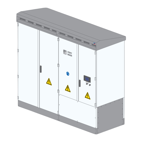
SMA Solar Technology AG 3 Product Overview 3 Product Overview Design of the Inverter Figure 1: Design of the Inverter Position Designation Inverter cabinet Interface cabinet Connection area Devices of the Inverter Figure 2: Inverter Components Position Component Description Touch Display Different kinds of inverter data can be viewed on the touch display. -
Page 14: Symbols On The Product
3 Product Overview SMA Solar Technology AG Position Component Description SC-COM The SC-COM is the communication unit of the inverter. The SC-COM estab- lishes the connection between the inverter and the system operator. AC disconnection unit With the AC disconnection unit, the electrical connection between the in- verter and MV transformer can be disconnected manually. -
Page 15: Transport And Mounting
SMA Solar Technology AG 4 Transport and Mounting 4 Transport and Mounting Safety during Transport and Mounting WARNING Danger of crushing if raised or suspended loads tip over, fall or sway Vibrations or careless or hasty lifting and transportation may cause the product to tip over or fall. This can result in death or serious injury. -
Page 16: Center Of Gravity Marker On The Inverter
4 Transport and Mounting SMA Solar Technology AG 4.2.2 Center of Gravity Marker on the Inverter The center of gravity of the inverter is not in the middle of the device. Take this into account during transport. The center of gravity of the inverter is marked on the packaging and on the enclosure with the center of gravity symbol. -
Page 17: Transporting The Inverter
SMA Solar Technology AG 4 Transport and Mounting 2. Seal the opening, e.g. with expanding foam. This will prevent living creatures from getting into the inverter. 3. Fill up the excavation pit and level off to ground level. Transporting the Inverter 4.3.1... -
Page 18: Transporting The Inverter Using A Crane
4 Transport and Mounting SMA Solar Technology AG 2. If a crane fork is used, move the forks of the crane fork under the inverter from the front or the back. Take the center of gravity of the inverter into account and move the crane fork completely under the inverter. - Page 19 SMA Solar Technology AG 4 Transport and Mounting Procedure: 1. Disassemble the ventilation grid (see Section 7.2.3, page 43). 2. Pull the front edge of the roof forward and push upward. 3. Gently push the roof to the rear. In doing so, you push the roof out of the guide rails.
-
Page 20: Mounting Of The Inverter
4 Transport and Mounting SMA Solar Technology AG 14. Slide the roof into the guide rails on the inverter and pull forward. 15. Press the roof down. 16. Mount the ventilation grids (see Section 7.2.3, page 43). Mounting of the Inverter 4.4.1... -
Page 21: Installation
SMA Solar Technology AG 5 Installation 5 Installation Safety during Installation DANGER Danger to life from electric shock due to live voltage High voltages are present in the live components of the product. Touching live components results in death or serious injury due to electric shock. -
Page 22: Preparing The Installation
5 Installation SMA Solar Technology AG WARNING Danger to life due to arc fault caused by damaged connection busbars If excessive force is exerted while connecting the cables, the connection busbars can be bent or damaged. This will lead to reduced clearances and creepage distances. Reduced clearances and creepage distances can lead to arc faults. -
Page 23: Replacing The Desiccant Bag In The Inverter
SMA Solar Technology AG 5 Installation Mounting the Rain Shield Required mounting material: ☐ 2 cylindrical screws ☐ 2 contact washers ☐ 6 pan head flange screws Procedure: 1. Position the rain shield on the silencing baffle. 2. Screw two cylindrical screws with contact washers into the bottom right and left threads on the cover and tighten them (torque: 8 Nm). -
Page 24: Installing The Dc Connection
5 Installation SMA Solar Technology AG Terminal lug requirements: ☐ Use tin-plated terminal lugs only. ☐ For the connection, only the supplied screws, washers and nuts must be used. ☐ The terminal lugs must be designed according to the temperature. Temperature: +95°C ☐... - Page 25 SMA Solar Technology AG 5 Installation ☐ The terminal lugs must be designed according to the temperature. Temperature: +95°C ☐ The width of the terminal lugs must exceed the washer diameter. Washer diameter: 32 mm. This will ensure that the defined torques are effective over the whole surface.
-
Page 26: Connecting The Dc Cables To The Connection Brackets
5 Installation SMA Solar Technology AG 5.4.2 Connecting the DC Cables to the Connection Brackets Figure 6: Connection area for DC fuses (example) Position Designation Connection area DC‒ Connection area DC+ DC connection bracket with dimensions Terminal lug requirements: ☐ Use tin-plated terminal lugs only. -
Page 27: Installing The Ac Connection
SMA Solar Technology AG 5 Installation Torques of the power connections: Type of terminal lug Torque Tin-plated aluminum or copper terminal lug on aluminum bar 37 Nm for M12 10 Nm for M8 Additionally required mounting material (not included in the scope of delivery): ☐... - Page 28 5 Installation SMA Solar Technology AG Inverter Maximum voltage to ground Sunny Central 800CP-JP ±1450 V Sunny Central 1000CP-JP ±1600 V ☐ The cables must be designed for the maximum root-mean-square value: Inverter Maximum root-mean-square value Sunny Central 500CP-JP 390 V Sunny Central 630CP-JP 800 V Sunny Central 800CP-JP 800 V Sunny Central 1000CP-JP 800 V ☐ Do not attach more than four cables to each AC connecting plate.
-
Page 29: Cables For Communication, Control, Supply Voltage And Monitoring
SMA Solar Technology AG 5 Installation Additionally required mounting material (not included in the scope of delivery): ☐ Clean cloth ☐ Ethanol cleaning agent Procedure: 1. Disassemble the panels (see Section 7.2.1, page 41). 2. Disassemble the protective covers (see Section 7.2.2, page 42). - Page 30 5 Installation SMA Solar Technology AG Additionally required mounting material (not included in the scope of delivery): ☐ 2 subscriber connectors NOTICE Damage to optical fibers due to too tight bend radii Excessive bending or kinking will damage the optical fibers.
-
Page 31: Connecting Optical Fibers Via Optical Fiber Pigtail
SMA Solar Technology AG 5 Installation 11. Attach the optical fibers to the cable support rail using a cable tie. This ensures that the optical fibers cannot be pulled out inadvertently. 12. Mount the panels (see Section 7.2.1, page 41). 5.6.2 Connecting Optical Fibers via Optical Fiber Pigtail... -
Page 32: Connecting The Network Cables
5 Installation SMA Solar Technology AG 5. Insert the optical fibers from below through the cable gland into the splice box. 6. Splice the optical fibers with the optical fiber pigtails in the splice box. 7. Plug the subscriber connectors into the SC-P plugs in the splice box. -
Page 33: Connecting Cables For Analog Setpoints
SMA Solar Technology AG 5 Installation 4. Attach the network cables to the cable support rail using a cable tie. This will prevent the network cables from being pulled out inadvertently. 5. Mount the panels (see Section 7.2.1, page 41). 5.6.4 Connecting Cables for Analog Setpoints If the setpoints for active power limitation and reactive power control are not transmitted via the network, there are terminals in the inverter for connecting external setpoints. -
Page 34: Connecting The Cable For Remote Shutdown
5 Installation SMA Solar Technology AG 5.6.6 Connecting the Cable for Remote Shutdown The remote shutdown enables the inverter to be switched off from a distance, e.g. from a control room. The function of the remote shutdown is similar to the stop function of the key switch. -
Page 35: Connecting The Cable For The Status Report Of The Ac Contactor Monitoring
SMA Solar Technology AG 5 Installation NOTICE Failure of the inverter due to incorrect connection of the internal power supply If the internal power supply is not properly connected, the residual-current device in the inverter may trip and put the inverter is no longer ready for operation. -
Page 36: Connecting The Transformer Protection
5 Installation SMA Solar Technology AG 5.6.11 Connecting the Transformer Protection The inverter is equipped with a terminal for monitoring the MV transformer. Under fault conditions, the inverter is immediately switched off. To use the transformer monitoring, an external supply voltage of 230 V must be provided in the MV transformer. -
Page 37: Disconnecting And Reconnecting
SMA Solar Technology AG 6 Disconnecting and Reconnecting 6 Disconnecting and Reconnecting Safety When Disconnecting and Reconnecting Voltage Sources DANGER Danger to life from electric shock due to live voltage High voltages are present in the live components of the product. Touching live components results in death or serious injury due to electric shock. -
Page 38: Disconnecting The Ac Side
6 Disconnecting and Reconnecting SMA Solar Technology AG 6.2.3 Disconnecting the AC Side 1. Switch off the inverter (see Section 6.2.1, page 37). 2. Disconnect the DC side (see Section 6.2.2, page 37). 3. Externally disconnect the AC voltage of the MV transformer. 4. Switch off the AC disconnection unit in the inverter. -
Page 39: Reconnecting The Inverter
SMA Solar Technology AG 6 Disconnecting and Reconnecting 6. Ensure that no voltage is present. 7. Cover or isolate any adjacent live components. Reconnecting the Inverter 6.3.1 Reconnecting the Supply Voltage at the Inverter 1. Close the measurement and disconnect terminals. -
Page 40: Reconnecting The Dc Side
6 Disconnecting and Reconnecting SMA Solar Technology AG 6.3.3 Reconnecting the DC Side 1. Insert all fuses and disconnection blades into all fuse holders of the inverter. Use an LV/HRC fuse extractor. 2. Screw on the protective covers over the fuses (torque: 5 Nm). -
Page 41: Periodic Actions
SMA Solar Technology AG 7 Periodic Actions 7 Periodic Actions Insert the cable into the inverter. 1. Remove the screws at the top of the sealing plate. 2. Remove the sealing plate. 3. Loosen the screws at the side of the sealing plate. -
Page 42: Disassembling And Mounting The Protective Covers
7 Periodic Actions SMA Solar Technology AG Disassembling the panels 1. Remove the screws of the front panels using a Torx screwdriver (head size T30). 2. Detach the grounding straps from the panels. 3. Remove the panels. Mounting the panels Requirement: ☐... -
Page 43: Disassembling And Mounting The Ventilation Grids
SMA Solar Technology AG 7 Periodic Actions DANGER Danger to life due to electric shock or electric arc if live components are touched • Switch off the inverter and wait at least 15 minutes before opening it to allow the capacitors to discharge completely. - Page 44 7 Periodic Actions SMA Solar Technology AG 4. Pull the lower side of the left-hand ventilation grid forwards to remove it. Mounting the ventilation grids 1. Insert the left-hand ventilation grid. 2. Screw the left-hand ventilation grid on (torque: 20 Nm,-head size T40).
-
Page 45: Bolted Connections
SMA Solar Technology AG 7 Periodic Actions Bolted Connections 7.3.1 Preparing the Grounding and DC Cables for Connection Connection overview with one two-hole terminal lug for grounding and DC cables Figure 12: Design of the connection with one two-hole terminal lug... - Page 46 7 Periodic Actions SMA Solar Technology AG Connection overview with one one-hole terminal lug for grounding and DC cables Figure 13: Design of the connection with one one-hole terminal lug Position Designation Nut M12 or M8 Spring washer (29 mm for M12 or 18 mm for M8) Fender washer (32 mm for M12 or 20 mm for M8)
- Page 47 SMA Solar Technology AG 7 Periodic Actions Connection overview with two two-hole terminal lugs for DC cables Figure 14: Design of the connection with two two-hole terminal lugs Position Designation Nut M12 Spring washer (29 mm) Fender washer (32 mm) Tin-plated two-hole terminal lugs...
- Page 48 7 Periodic Actions SMA Solar Technology AG Connection overview with two one-hole terminal lugs for DC cables Figure 15: Design of the connection with two one-hole terminal lugs Position Designation Nut M12 or M8 Spring washer (29 mm for M12 or 18 mm for M8) Fender washer (32 mm for M12 or 20 mm for M8)
-
Page 49: Preparing The Ac Connection
SMA Solar Technology AG 7 Periodic Actions 7.3.2 Preparing the AC Connection Overview of the connection with one one-hole terminal lug Figure 16: Design of the connection with one one-hole terminal lug Position Designation Nut M12 Spring washer (29 mm) Fender washer (32 mm) -
Page 50: Clamp Connections
7 Periodic Actions SMA Solar Technology AG Connection overview with two one-hole terminal lugs Figure 17: Design of the connection with two one-hole terminal lugs Position Designation Nut M12 Spring washer (29 mm) Fender washer (32 mm) Tin-plated one-hole terminal lugs Connection busbar... -
Page 51: Connecting The Cable Shield Using A Shield Clamping Saddle
SMA Solar Technology AG 7 Periodic Actions 2. Strip the insulation of the insulated conductors. 3. Connect the cable in accordance with the circuit diagram. • Remove the connection plug from the base terminal. • Insert the screwdriver in the square opening of the connection plug. - Page 52 7 Periodic Actions SMA Solar Technology AG 2. Press the shield clamping saddle down onto the shield of the stripped cable until it snaps into place and fasten hand-tight. SCCP-JP-B1-IA-en-21 Installation Manual...
-
Page 53: Technical Data
SMA Solar Technology AG 8 Technical Data 8 Technical Data Sunny Central 500CP-JP DC Input Maximum DC power 511 kW Maximum input voltage 600 V MPP voltage range at 50 Hz 332 V to 600 V MPP voltage range at 60 Hz 332 V to 600 V DC voltage range at 50 Hz 311 V to 600 V... - Page 54 8 Technical Data SMA Solar Technology AG AC Output Displacement power factor cos φ 0.9 overexcited to 0.9 underexcited Feed-in phases Connection phases Inrush current of the internal power supply 48 A (100 ms) * For order option "Noise reduction", the values change (see datasheet).
-
Page 55: Sunny Central 630Cp-Jp
SMA Solar Technology AG 8 Technical Data General Data Fresh air consumption 3000 m³/h * For order option "Noise reduction", the values change (see datasheet). Sunny Central 630CP-JP DC Input Maximum DC power 713 kW Maximum input voltage 1000 V MPP voltage range at 50 Hz 500 V to 850 V... - Page 56 8 Technical Data SMA Solar Technology AG AC Output Maximum total harmonic distortion 3 % Power factor at rated power Displacement power factor cos φ 0.9 overexcited to 0.9 underexcited Feed-in phases Connection phases Inrush current of the internal power supply 48 A (100 ms) * For order option "Noise reduction", the values change (see datasheet).
-
Page 57: Sunny Central 800Cp-Jp
SMA Solar Technology AG 8 Technical Data General Data Maximum operating altitude above mean sea level 2000 m Fresh air consumption 3000 m³/h * For order option "Noise reduction", the values change (see datasheet). Sunny Central 800CP-JP DC Input Maximum DC power 898 kW Maximum input voltage 1000 V... - Page 58 8 Technical Data SMA Solar Technology AG AC Output Maximum overcurrent protection at output 50000 A Maximum total harmonic distortion 3 % Power factor at rated power Displacement power factor cos φ 0.9 overexcited to 0.9 underexcited Feed-in phases Connection phases Inrush current of the internal power supply 48 A (100 ms) * For order option "Noise reduction", the values change (see datasheet).
-
Page 59: Sunny Central 1000Cp-Jp
SMA Solar Technology AG 8 Technical Data General Data Maximum permissible value for relative humidity (non- 15% to 95% condensing) Maximum operating altitude above mean sea level 2000 m Fresh air consumption 3000 m³/h * For order option "Noise reduction", the values change (see datasheet). - Page 60 8 Technical Data SMA Solar Technology AG AC Output Maximum residual current at the AC output 3500 A Maximum overcurrent protection at output 50000 A Maximum total harmonic distortion Power factor at rated power Displacement power factor cos φ 0.9 overexcited to 0.9 underexcited Feed-in phases...
- Page 61 SMA Solar Technology AG 8 Technical Data General Data Degree of protection of the connection area IP43 Maximum permissible value for relative humidity (non- 15% to 95% condensing) Maximum operating altitude above mean sea level 2000 m Fresh air consumption 3000 m...
-
Page 62: Appendix
9 Appendix SMA Solar Technology AG 9 Appendix Information for Installation 9.1.1 Requirements for the Mounting Location ☐ The mounting location must be freely accessible at all times. ☐ The fresh air requirement of the inverter amounting to 3000 m /h must be assured. -
Page 63: Requirements For The Support Surface
9.1.3 Requirements for the Foundation and Cable Routing If you do not use a base from SMA Solar Technology AG, you can also position the inverter on a foundation. The foundation must have the following properties: ☐ The foundation must be suitable for the weight of the inverter. The inverter weighs: 1800 kg. -
Page 64: Requirements For Cable Routing Between Mv Transformer And Inverter
9 Appendix SMA Solar Technology AG ☐ The inclination of the foundation must be between 0.5% and 1%. This will allow rain water to drain from underneath the inverter. ☐ The foundation must have at least the following dimensions: Position... - Page 65 AC cables must be fitted with ring terminal lugs and must be designed for operation at such high temperatures. SMA Solar Technology AG recommends the use of cable sets supplied by SMA. These are designed for temperatures of up to +100°C.
-
Page 66: Dimensions Of The Inverter
9 Appendix SMA Solar Technology AG Figure 18: Arrangement of AC cables with three cables per line conductor (example) Position Designation Line conductor L1 Line conductor L2 Line conductor L3 Grounding strap 9.1.5 Dimensions of the Inverter Dimensions of the inverter with roof... - Page 67 SMA Solar Technology AG 9 Appendix Dimensions of the optionally available silencing baffle Figure 20: Dimensions of the silencing baffle Dimensions of the inverter without roof Figure 21: Dimensions of the inverter without roof Installation Manual SCCP-JP-B1-IA-en-21...
-
Page 68: Minimum Clearances
9 Appendix SMA Solar Technology AG 9.1.6 Minimum Clearances 9.1.6.1 Minimum Clearances for Outdoor Installation NOTICE Damage due to intake of exhaust air or blocked ventilation openings The supply air is intended to cool the inverter components. Failure to observe the specified minimum clearances can result in warm exhaust air from the inverter being drawn in. - Page 69 SMA Solar Technology AG 9 Appendix Minimum clearances between two inverters and transformer Version 1: Rear to rear 300 mm 1200 mm 300 mm Figure 23: Minimum clearances between two inverters and transformer Position Designation Inverter 1 Inverter 2 MV transformer and medium-voltage switchgear...
- Page 70 9 Appendix SMA Solar Technology AG Minimum clearances between two inverters and transformer Version 2: Front to front Figure 24: Minimum clearances between two inverters and transformer Position Designation Inverter 1 Inverter 2 MV transformer and medium-voltage switchgear Cable route between inverter and MV transformer Recommended clearances for the facilitation of service work In order to facilitate service work, minimum clearances to the rear and sides of 1000 mm are recommended.
-
Page 71: Minimum Clearances In Electrical Equipment Rooms
SMA Solar Technology AG 9 Appendix 9.1.6.2 Minimum Clearances in Electrical Equipment Rooms The option "Noise reduction" is not recommended for the option "Station installation" and therefore not further considered. NOTICE Damage due to intake of exhaust air or blocked exhaust air outlets The supply air is intended to cool the inverter components. -
Page 72: Grounding Concept
9 Appendix SMA Solar Technology AG Minimum clearances for two inverters to be installed in electrical equipment rooms WARNING Danger to life due to blocked escape routes In hazardous situations, blocked escape routes can lead to death or serious injury. Opening the doors of two products located opposite each other can block the escape route. -
Page 73: Storage
SMA Solar Technology AG 9 Appendix Storage If you need to store the inverter prior to final installation, note the following points: NOTICE Property damage due to dust intrusion and moisture penetration Dust or moisture intrusion can damage the product and impair its functionality. -
Page 74: Reduction Of Dc Input Currents For Dc Fuses
9 Appendix SMA Solar Technology AG Torques at panels, covers and grounding conductor: Position Torque Grounding conductors on the kick plates 8 Nm to 10 Nm Mounting the kick plates 2 Nm to 3 Nm Grounding conductor on the roof 14.2 Nm Mounting the ventilation grids on the roof 20 Nm... - Page 75 SMA Solar Technology AG 9 Appendix Scope of Delivery of the Inverter Figure 27: Scope of delivery Position Quantity Designation Inverter Ventilation plate Kick plate Low-voltage HRC fuse handle (optional) Non-woven abrasive Desiccant bag Bolt M12 Bolt M8 Nut M12 Nut M8 Fender washer (32 mm)
- Page 76 9 Appendix SMA Solar Technology AG Position Quantity Designation Touch-up stick RAL 9016 Circuit diagram, documentation, report Position of the LV/HRC fuse handle The LV/HRC fuse handle is located on the inside of the right-hand interface cabinet door. Scope of delivery with order option "Noise reduction"...
- Page 77 SMA Solar Technology AG 10 Contact 10 Contact If you have technical problems concerning our products, contact your service partner. The following data is required in order to provide you with the necessary assistance: • Device type • Firmware version •...
- Page 78 www.SMA-Solar.com...
Need help?
Do you have a question about the SUNNY CENTRAL 500CP-JP and is the answer not in the manual?
Questions and answers