
Related Manuals for SMA SUNNY CENTRAL 250U


Summary of Contents for SMA SUNNY CENTRAL 250U
- Page 1 Central Inverter SUNNY CENTRAL 250U / 500U / 500HE-US / 500HE-CA User Manual SCUS-BE-BUS111113 | 98-4000613 | Version 1.3...
- Page 3 All such warranties are expressly disclaimed. Neither SMA America, LLC nor its distributors or dealers nor SMA Solar Technology Canada Inc. nor its distributors or dealers shall be liable for any indirect, incidental, or consequential damages under any circumstances.
-
Page 4: Important Safety Instructions
A Warning describes a hazard to equipment or personnel. It calls attention to a procedure or practice, which, if not correctly performed or adhered to, could result in damage to or destruction of part or all of the SMA equipment and/or other equipment connected to the SMA equipment or personal injury. -
Page 5: Other Symbols
SMA America, LLC Other Symbols In addition to the safety and hazard symbols described on the previous pages, the following symbol is also used in this Installation Guide: Information This symbol accompanies notes that call attention to supplementary information that you should know and use to ensure optimal operation of the system. - Page 6 SMA assumes no responsibility for the compliance or noncompliance with such laws or codes in connection with the installation of the SMA inverter. Before installing or using the Sunny Central, read all of the instructions, cautions, and warnings on the Sunny Central, the PV array, in this Installation Guide and in User Manual.
-
Page 7: Table Of Contents
SMA America, LLC Table of Contents Table of Contents Information on this Manual......9 Target Group ........9 Validity . - Page 8 Table of Contents SMA America, LLC Changing Parameters ....... . 32 Error Diagnosis.
-
Page 9: Information On This Manual
PV modules. 1.1 Target Group This manual is for the installer, the maintenance personnel and the operator of a Sunny Central 250U, Sunny Central 500U and Sunny Central 500HE-US. The installer, the maintenance personnel and the operator of the Sunny Central have to be qualified personnel. Qualified personnel has received training and has demonstrated skills and knowledge in the construction and operation of the device. -
Page 10: Safety Instructions
• All work on the Sunny Central may only be done as described in this manual. • Pay attention to all safety instructions. • Follow all operating instructions. • If problems occur when performing the work described here, contact SMA America. WARNING Operating a damaged Sunny Central may cause severe injury from electric shock. -
Page 11: Description Of The Sunny Central
The Sunny Central is a PV inverter that converts the DC energy from PV modules to AC energy. This energy is then fed to the public grid. The Sunny Central is designed for indoor and outdoor installation. Principle of a PV Power System with a Sunny Central 250U or Sunny Central 500U Stop... - Page 12 SMA America, LLC Principle of a PV Power System with a Sunny Central 500HE-US Position Description PV modules DC distribution with DC fuses (e.g., Sunny Central String-Monitor) DC disconnect Sunny Central Transformer Public grid SCUS-BE-BUS111113 User Manual...
-
Page 13: Design Of The Sunny Central
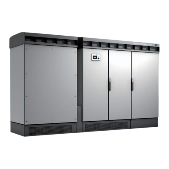
SMA America, LLC 3.1 Design of the Sunny Central Sunny Central 250U Sunny Central 500U Position Cabinet Description Magnetics Cabinet The Sunny Central's transformer is contained in the Magnetics Cabinet. Control Cabinet The Control Cabinet contains the system control, the Sunny Display, the stop/start switch and the stacks for converting direct current to alternating current. -
Page 14: Location Of The Safety Instructions
• stop/start switch • optional communication devices 3.2 Location of the Safety Instructions Sunny Central 250U The figure to the right shows the location of the safety instructions on the Sunny Central 250U. Position Description Wall of the Magnetics Cabinet General warnings... - Page 15 SMA America, LLC Sunny Central 500U The figure to the right shows the location of the safety instructions on the Sunny Central 500U. Position Description Wall of the Magnetics Cabinet General warnings Door of the Control Cabinet and Interface Cabinet Warning regarding high voltages in the Sunny Central.
-
Page 16: Identifying The Sunny Central
SMA America, LLC 3.3 Identifying the Sunny Central You can identify the Sunny Central using the type plate (see figure at right, example for a typeplate of the Sunny Central 500U). The type plate is located in the Interface Cabinet. Position... -
Page 17: Elements For Sunny Central Operation
For this purpose, the Sunny SensorBox is equipped as standard with an integrated irradiation sensor and an external module temperature sensor. The Sunny SensorBox delivers the sensor data via an RS485 interface to the SMA communication devices (e.g. Sunny WebBox). -
Page 18: Operating The Sunny Display
SMA America, LLC 4 Operating the Sunny Display 4.1 Functions of the Buttons Position Description Pushbutton Knob The display can be operated with a pushbutton and a knob. Pushbutton If an error occurs during operation, the pushbutton is backlit red. The display indicates the error with a number and a description in the text line. -
Page 19: Description Of Display Symbols
SMA America, LLC 4.2 Description of Display Symbols The following figure is an example for the Sunny Central 250U. Postion Description Tapping The background illumination is switched on by tapping on the housing cover. Open switch: The Sunny Central is not feeding the grid (e.g., at night). - Page 20 In addition, a message in plain text will be shown in the text line (position F). See Section 7 ”Error Diagnosis” (page 33). Errors This symbol is illuminated if an error occurs. Contact the SMA Serviceline, see Section 9 ”Contact” (page 44). Errors This symbol is illuminated if an error occurs.
-
Page 21: Navigating Through The Menu
SMA America, LLC 4.3 Navigating through the Menu You can navigate through the menu using the knob and the pushbutton on the Sunny Display. Action Procedure Change menu item Turn knob. Select menu Press knob once. Leave menu Turn the knob until the text line reads "BACK". -
Page 22: Menu Overview
SMA America, LLC Switching between E-DAY and E-HISTORY You change the display by turning the knob. Turn the knob to the left: E-HISTORY Turn the knob to the right: E-DAY 4.5 Menu Overview The menu of the Sunny Display is subdivided into two menu items. To access the menu, proceed as follows: 1. -
Page 23: Description Of Menu Items
SMA America, LLC 4.5.1 Description of Menu Items SETTINGS In the Settings menu you can adjust the settings on the display (e.g. date and time settings) and display the current time. • CURRENT TIME Displays the current time. • TIME SETTINGS In this menu you can change the time and the date (see Section 4.6 ”Changing Date and Time”... -
Page 24: Changing Date
SMA America, LLC 10. Turn the knob until the text line displays the desired hour. 11. Press the knob once to confirm and save the current value. The Sunny Display springs back to the "SET CURRENT TIME" menu. The value (in this case the hour) is set. - Page 25 SMA America, LLC 5. Press the knob once. The Sunny Display shows the version number of the operation control unit. 6. Press the knob once to spring back one level. User Manual SCUS-BE-BUS111113...
-
Page 26: Spot Values
SMA America, LLC 5 Spot Values The following table shows the spot values that are visible to the user. The spot values are part of the channel list and display the Sunny Central‘s status. Name Description Cntry Country code Error description... - Page 27 In section 7 ”Error Diagnosis” (page 31) it is described how this error can be rectified. • Telephone receiver (the Sunny WebBox shows plain text message „Prio_A“): Contact the SMA Serviceline, see section 8 ”Contact” (page 39). AC reactive power SerTm Current time in seconds since 01.01.1970...
-
Page 28: Parameters
SMA America, LLC 6 Parameters 6.1 Description of Parameters The following table shows the parameters that are visible to the user. The installation guide of the Sunny Central also shows the parameters that are visible to the installer. Parameter Name Range Default... - Page 29 ChkGnFrqLo Sunny Central operation with a generator. ChkGnFrqLoT More information on parameter settings ChkGnFrqMax and operating the Sunny Central with a ChkGnFrqMin generator can be obtained from SMA ChkGnVtgHi America. ChkGnVtgLo ChkGnVtgMax ChkGnVtgMin yyyymmdd Current Date. Here you can set the current date.
- Page 30 SMA America, LLC Parameter Name Range Default Parameter Description Ofs_h-Total 0 ... 2147483 h Total number of operational hours with grid feeding Changing the Ofs_h_Total parameter may be necessary if you exchange the computer assembly (BFR) of the Sunny Central and want to transfer the data from the old device.
- Page 31 SMA America, LLC Parameter Name Range Default Parameter Description SpntRemEna –––, Off, On Switching off the Sunny Central With this parameter you can switch off the Sunny Central via the remote access. hhmmss Current Time. Here you can set the current time.
-
Page 32: Changing Parameters
If a Sunny WebBox is installed in the Sunny Central, you can change the parameters of the Sunny Central via remote access from a PC or laptop. If you want to change the parameters of a Sunny Central without an inbuilt Sunny WebBox, contact SMA America. Change the parameters as described in the following: 1. -
Page 33: Error Diagnosis
• All the safety instructions in the installation guide and user manual must be observed when working on the Sunny Central. • Contact SMA America if you cannot rectify the fault with the help of this manual. Example of an Isolation Failure The pushbutton glows to indicate a failure. -
Page 34: Diagnosis
SMA America, LLC 7.1 Diagnosis The displayed faults are divided into the three areas of the PV system: • PV generator (see Section 7.1.1 ”PV Generator Fault” (page 34)). • Sunny Central (see Section 7.1.2 ”Sunny Central Fault” (page 35)). • Grid (see Section 7.1.3 ”Grid Fault” (page 37)). -
Page 35: Sunny Central Fault
Description Error text: Device Fault Cause of fault: • Internal fault of the Sunny Central. Corrective measures: • Contact the SMA Serviceline. Error text: Device Fault Cause of fault: Internal fault of the Sunny Central. Corrective measures: • Contact the SMA Serviceline. - Page 36 • Cable break • Short circuit • Internal fault of the Sunny Central. Corrective measures: • Check the cabling of the temperature sensor. • Contact the SMA Serviceline. Error text: Fan failure Cause of fault: The ambient temperature is too high.
-
Page 37: Grid Fault
SMA America, LLC Description Error text: Device fault Cause of fault: Contactor defective. Corrective measures: • Contact the SMA Serviceline. Error text: Surge voltage arrestor failure Cause of fault: Surge error. Corrective measures: • Check surge voltage arrestor. Error text:... - Page 38 SMA America, LLC Description Error text: Grid fault Cause of fault: The grid voltage is too low. Corrective measures: • Check the grid voltage. • If the grid voltage lies outside the acceptable range because of local grid conditions, ask the grid operator if the voltages can be adjusted at the feed-in point.
-
Page 39: Display Fault
– WEBBOX: For this operating mode a Sunny WebBox has to be installed. – NO WEBBOX: No Sunny WebBox installed. • For operation with Sunny WebBox: Check function of the Sunny WebBox. • Contact the SMA Serviceline. 7.1.5 Acknowledge Error at the Sunny Display Acknowledge the error as described in the following. -
Page 40: Acknowledge The Error With The Sunny Webbox
SMA America, LLC 7.1.6 Acknowledge the Error with the Sunny WebBox If a Sunny WebBox is installed in the Sunny Central, you acknowledge an error via a Sunny WebBox from a PC or Laptop. You will find an extensive description of the operation of the Sunny WebBox in the technical description of the Sunny WebBox. -
Page 41: Appendix - Glossary
SMA America, LLC 8 Appendix - Glossary Abbreviation for "Alternating Current" ANSI Abbreviation for American National Standards Institute Abbreviation for operation control unit CANDI Fimware version of internal CAN communication Abbreviation for California Energy Commission Crossover cable A crossover cable is needed, for example, to connect two computers directly with one another. A crossover cable is an 8-wire twisted pair cable with an RJ45 plug on each end. - Page 42 SMA America, LLC Maximum Power Point (MPP) Operating point with the maximum output power. This operating point varies with the PV radiation and temperature conditions of the modules. NEMA Abbreviation for National Electrical Manufactures Association NFPA Abbreviation for National Fire Protection Association Patch Cable A patch cable is used, for example, to connect a computer to a switch or router.
-
Page 43: Sunny Portal
Sunny Portal Sunny Portal is a web-based service provided by SMA which offers the possibility of creating a personal Sunny Portal website on which the data pertaining to a photovoltaic plant can be displayed. Additionally, the Sunny Portal archives this data. The PV power system data is available worldwide over the Internet. -
Page 44: Contact
SMA America, LLC 9 Contact If you have technical problems concerning our products, contact the SMA Serviceline. We require the following information in order to provide you with the necessary assistance: • Inverter type • Type and number of modules connected •... - Page 45 SMA America, LLC User Manual SCUS-BE-BUS111113...
- Page 46 SMA America, LLC SCUS-BE-BUS111113 User Manual...
- Page 48 SMA A...
Need help?
Do you have a question about the SUNNY CENTRAL 250U and is the answer not in the manual?
Questions and answers