Sign In
Upload
Manuals
Brands
Sutter Instrument Manuals
Laboratory Equipment
Lambda DG-4
Sutter Instrument Lambda DG-4 Manuals
Manuals and User Guides for Sutter Instrument Lambda DG-4. We have
1
Sutter Instrument Lambda DG-4 manual available for free PDF download: Operation Manual
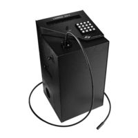
Sutter Instrument Lambda DG-4 Operation Manual (86 pages)
Ultra-High-Speed Wavelength Switching Illumination System
Brand:
Sutter Instrument
| Category:
Laboratory Equipment
| Size: 1 MB
Table of Contents
Disclaimer
5
Safety Warnings and Precautions
5
Electrical
5
Avoiding Electrical Shock and Fire-Related Injury
6
Electromagnetic Interference
6
Operational
6
Avoiding Physical Injury While Powered up and Emitting Light
6
Avoiding Physical Injury and Equipment Damage While Replacing the Xenon Bulb
7
Table of Contents
10
1 General Information
15
Introduction
15
How to Use this Manual
15
Technical Support
15
General Description
15
Figure 1-1. Lambda DG-4/5 Optical Pathway
16
Lambda DG-4 and Lambda DG-5
17
Systems
17
2 Installation
19
Unpacking
19
Getting Started
19
Figure 2-1. Light Guide Installation
19
Figure 2-2. Lambda DG-4/5 Left Side
20
Light Guide & Optical Holder Installation
22
Liquid Light Guide
22
Liquid Light Guide Installation
22
Optical Holder
22
Figure 2-3. Liquid Light Guide Installation
22
Loading Filters
23
Filter Orientation
23
Figure 2-4. Light Guide Optical Holder
23
Figure 2-5. Filter Holder Assembly
23
Selection of a Filter Position
24
Blanking Discs
24
Neutral Density Filters
24
Figure 2-6. Filter Holder Assembly with Blanking Disc
24
Filter Holder Installation
25
Figure 2-7. Lambda DG-4/5 Left Side
25
3 Operations
27
Control Electronics
27
Preparation and Precautions
27
Power-Up Sequence
27
Top Panel Controls
28
Keypad
28
Figure 3-1. Keypad (Top Panel)
28
Electrical Connections
29
Parallel Port
30
Serial Port
30
Filter Value out
30
Figure 3-2. Electrical Connections (Rear Panel)
30
Sync
31
Dac
31
Strobe
31
Line Power
31
Fuse
31
Modes of Operation (LOCAL)
31
General Information
31
Figure 3-3. Filter Value out Connector
31
Selecting an Operational Mode: the MODE Key
32
Move on Command Mode
33
Move on Sync Pulse Mode
34
Move on Strobe Pulse Mode
35
Move on Sync, Inhibited by the Strobe Line Mode
36
Edit a Filter Definition Mode
37
General Information
37
Filter Numbers
38
Figure 3-4. Optical Pathway Based on Filter Position
38
Table 3-1. Input and Output Galvanometer Values Based on Filter Position
38
Attenuation
39
Figure 3-5. DG-4/5 Output Attenuation
39
Figure 3-6. Log of Attenuation Vs. Change in Output Galvanometer Value
39
Programming a Filter Number ("Logical Filter")
40
Manual Adjustment of Attenuation
41
Setup Ring Buffer Mode
42
General Information
42
Storing the FILTER NUMBER Sequence
43
Viewing an Existing FILTER NUMBER Sequence
44
Running the RING BUFFER Sequence
45
Turbo-Blanking Mode
46
Display the First Four Filter Values Mode
47
4 External Control Operations
49
Parallel Interface
49
Connecting to the Lambda DG-4/5 Parallel Port
49
Figure 4-1. Parallel Port DB25 Connector (Male)
49
Table 4-1. Parallel Port Pin Assignments
49
Input Lines
50
Command Codes
50
Table 4-2. Command Code Types
50
Table 4-3. DG-4-Only Filter Position Movement Commands
51
Table 4-4. DG-5-Only Filter Position Movement Commands
52
Table 4-5. Controller Commands
53
Busy Line
54
Interface Modes
55
Controlling the Lambda DG-4/5 from a Computer's Parallel (Printer) Port
55
Figure 4-2. DB25 Parallel Connector
56
Table 4-6. Parallel Port Pin Connections and Definitions
56
Reading the Status of the Lambda DG-4/5
57
Table 4-7. Parallel Port Numbering and Addressing
57
Shutter Control
59
Serial Interface
59
Connecting to the Lambda DG-4/5 Serial Input
59
Table 4-8. Shutter Open and Close Commands
59
Controlling the Lambda DG-4/5 from a Computer's Serial Port
60
Figure 4-3. Serial Control Connections (Viewed from Rear of Cabinet)
60
Serial Port Command Echo
61
Serial Port Command Completion Indicator
61
Reading the Status of the Lambda DG-4/5
61
Listing 4-2. Command Echo Check Routine
61
Listing 4-3. Command-Completion Check Routine
61
Listing 4-4. Reading the Lambda DG-4/5'S Status
62
5 Maintenance
65
Changing the Xenon Arc Bulb
65
Bulb Assembly
65
Figure 5-1. Lamp Bulb Assembly Components
65
Removing the Lamp Assembly from the System
66
Figure 5-2. Lamp Cover Panel on Left Side of the Lambda DG-4/5-Series Cabinet
66
Bulb Replacement
67
Removing the Existing Bulb
67
Installing the New Bulb
67
Figure 5-3. Heat Sink Retaining-Clip Removal
67
Figure 5-4. Bulb Surfaces Requiring They be Covered with Thermal Compound
68
Figure 5-5. Heat Sink Alignment and Positioning of the Retaining Clips
68
Reinstalling the Lamp/Housing Assembly to the System
69
Figure 5-6. Position of the Bulb/Heat Sink Assembly in the Blue Housing
69
Figure 5-7. Returning the Light Bulb Assembly to the System
69
Appendix A. Limited Warranty
71
Appendix B. Accessories
73
Liquid Light Guides and Other Accessories
73
Microscope Mounting Adapters
73
Xenon Arc Lamp Bulbs
73
18Mm Interference Filter Accessories
74
Neutral Density Filter Accessories
74
Smartshutter
74
Appendix C. Fuse Replacement
75
Figure 5-8. Fuse Replacement
75
Tablec-1. Mains Fuse Requirements According to Lamp Power Ratings and Line Voltage
76
Appendix D. Technical Specifications
77
Table D-1. Cable Specifications
78
Appendix E. External-Control Command Reference
79
Table E-1. Filter-Selection Command Reference
79
Table E-2. Filter Selection Command Structure
80
Table E-3. Special Commands Reference
80
Index
83
Advertisement
Advertisement
Related Products
Sutter Instrument Lambda DG-5
Sutter Instrument Lambda 10-3
Sutter Instrument LAMBDA 10-B
Sutter Instrument Lambda DG-4Plus/USB
Sutter Instrument Lambda DG-5Plus/USB
Sutter Instrument Lambda 10-2
Sutter Instrument Lambda 10-232S
Sutter Instrument Lambda 10-250
Sutter Instrument Lambda 10-232
Sutter Instrument Lambda 10-2S
Sutter Instrument Categories
Laboratory Equipment
Amplifier
Control Systems
Controller
Work Light
More Sutter Instrument Manuals
Login
Sign In
OR
Sign in with Facebook
Sign in with Google
Upload manual
Upload from disk
Upload from URL