
Related Manuals for Skyjack SJ 7135


Summary of Contents for Skyjack SJ 7135
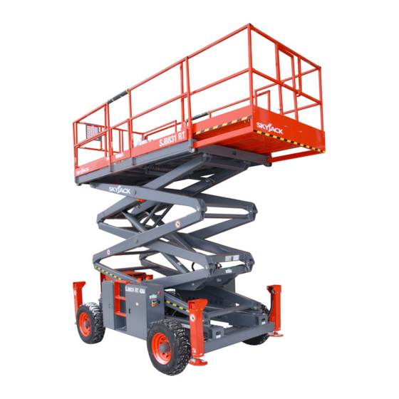
- Page 1 MODELS SJ 7127 SJ 7135 SJ 8831 SJ 8841 SJ 9250 Operating Manual Mid-Size & Full-Size Rough Terrain Series (AS) 157938AA-A April 2011...
- Page 2 SJRT 71XX 34,001,951 & Above SJRT 8831 36,000,233 & Above SJRT 8841 40,000,728 & Above SJRT 9250 50,000,746 & Above Please refer to the website (www.skyjack.com) for older Serial Numbers. Skyjack Service Center 3451 Swenson Ave. St. Charles, Illinois, 60174 USA Phone: 630-262-0005...
- Page 3 The Safety Alert Symbol identifies important safety messages on aerial platform, safety signs This Safety Alert Symbol means attention! in manuals or elsewhere. When you see this symbol, be alert to the possibility of personal Become alert! Your safety is involved. injury or death.
-
Page 4: Table Of Contents
Table of Contents Section 1 - About Your Aerial Platform ....................5 Reed and Heed ..............................5 Safety Rules ................................6 Section 2 - Familiarization ........................11 Familiarization of SJRT Mid Size and Full Size Series ..............11 Component Identification .........................12 Visual & Daily Maintenance Inspections ..................16 Function Tests ..........................26 Winching and Towing Procedure .....................36 Emergency Lowering Procedures ....................37... -
Page 5: Section 1 - About Your Aerial Platform
SKYJACK warrants each new SJRT Series aerial platform to be free of defective parts and workmanship for the first 24 months. Any defective part will be replaced or repaired by your local SKYJACK dealer at no charge for parts or labor. -
Page 6: Safety Rules
Common sense dictates the use of protective clothing when working on or near machinery. Use appropriate safety devices to protect your eyes, ears, hands, feet and body. Any modifications from the original design are strictly forbidden without written permission from SKYJACK. Electrocution Hazard This aerial platform is not electrically insulated. - Page 7 Section 1 - About Your Aerial Platform Safety Rules Safety Precautions Know and understand the safety precautions before going on to next section. WARNING Failure to heed the following safety • DO NOT increase the lateral precautions could result in tip over, surface area of the platform.
- Page 8 Safety Rules Section 1 - About Your Aerial Platform Safety Precautions (Continued) Know and understand the safety precautions before going on to next section. • DO NOT operate on surfaces not capable • DO NOT raise the platform of holding the weight of the aerial platform while the aerial platform is on a including the rated load, e.g., covers, drains, and truck, forklift or other device or...
- Page 9 • has been tagged or locked out for non-use or or materials that exceed the confines of the repair. guardrails unless approved by Skyjack. Failure to avoid these hazards could WARNING result in death or serious injury.
-
Page 10: Section 2 - Familiarization
Section 2- Familiarization SJRT Series 2.1 Familiarization of SJRT Mid Size and Full Size Series WARNING Aerial Platform Familiarization should be given only to individuals who are QUALIFIED And TRAINED to operate an aerial platform. Do not operate this aerial platform without proper authorization and training. Failure to avoid this hazard could result in death or serious injury. -
Page 11: Component Identification
Control Functions Section 2 - Familiarization 2.2 Component Identification 2.2-4 Load Sensing System This system is a safety device that prevents any normal The following descriptions are for identification, movement of the aerial platform from a stationary explanation and locating purposes only. working condition after the rated load is reached and 2.2-1 Main Power Disconnect Switch exceeded. - Page 12 Section 2 - Familiarization Control Functions 2.2-5 Base Control Console 2.2-6 Brake System This control console is located at the rear of the The brake system is located on the main manifold in hydraulic/electrical compartment. It contains the the hydraulic/electrical compartment. The brake must following controls: be manually disengaged before pushing, winching or towing.
- Page 13 Control Functions Section 2 - Familiarization 2.2-8 Emergency Lowering System 2.2-9 Engine Control Console This emergency lowering system allows platform This control console is attached to the engine tray. It lowering in the event of an emergency or an electrical contains the following controls: system failure.
- Page 14 Section 2 - Familiarization Control Functions 2.2-10 Platform Control Console Lift Enable Pushbutton - When depressed and This removable control console is mounted at the right held, this “ ” pushbutton allows the lift front of the platform. It contains the following controls: functions to operate.
-
Page 15: Visual & Daily Maintenance Inspections
Visual & Maintenance Inspection Section 2 - Familiarization Model 71xx Model 88xx Platform Control Console Platform Assembly Scissor Assembly Limit Switch Outrigger Ladder Ladder Base Electrical/Hydraulic Electrical/Hydraulic Base Limit Switch Compartment Compartment 2.3 Visual & Daily Maintenance Inspect the following areas for chafed, corroded and loose wires: Inspections • base to platform cables and wiring harness... - Page 16 Section 2 - Familiarization Visual & Maintenance Inspection Typical Model 71xx shown Emergency Lowering Access Rod Electrical Panel Main Manifold Main Power Disconnect Switch Load/Tilt Sensor Base Control Switches Motion Control Manifold Cushion Cylinder Brake Manifold 2.3-6 Hydraulic/Electrical Compartment WARNING Ensure all compartment latches are secure Battery acid is extremely corrosive - and in proper working order.
- Page 17 Visual & Maintenance Inspection Section 2 - Familiarization Typical Model 71xx shown Emergency Lowering Access Rod Electrical Panel Main Manifold Main Power Disconnect Switch Load/Tilt Sensor Base Control Switches Motion Control Manifold Cushion Cylinder Brake Manifold • Manifolds • Hydraulic Oil Ensure all fittings and hoses are properly Ensure platform is fully lowered, and tightened and there is no evidence of...
- Page 18 Section 2 - Familiarization Visual & Maintenance Inspection Typical Model 71xx shown Fuel Tank Hydraulic Tank 2.3-7 Hydraulic/Fuel Compartment • Fuel Leaks Ensure all compartment latches are Ensure that there no fuel leaks. secure and in proper working order. DANGER • Hydraulic Tank (Models 71xx &...
- Page 19 Visual & Maintenance Inspection Section 2 - Familiarization Typical Model 71xx shown Muffler and Exhaust Engine Radiator Engine Control Console Engine Air Filter Hydraulic Pump Engine Tray Battery 2.3-8 Engine Compartment • Engine Tray Ensure there are no loose or missing parts and no visible damage to the engine WARNING tray.
- Page 20 Section 2 - Familiarization Visual & Maintenance Inspection Typical Model 71xx shown Muffler and Exhaust Engine Radiator Engine Control Console Engine Air Filter Hydraulic Pump Engine Tray Battery • Engine Oil Level Ensure fuel pump, fuel filter, hoses and Maintaining the engine components fittings show no visible damage and no is essential to good performance and evidence of fuel leakage.
- Page 21 Visual & Maintenance Inspection Section 2 - Familiarization Platform Railing Platform Control Platform Console Assembly 2.3-9 Platform Assembly • Platform Control Console Ensure all switches and controller are returned to neutral and are properly WARNING secured. Ensure that you maintain three points of contact to mount/dismount platform.
- Page 22 Section 2 - Familiarization Visual & Maintenance Inspection Scissor Assembly Slider Scissor Bumper Maintenance Limit Switch Support Lift Cylinder 2.3-10 Lifting Mechanism • Scissor Bumpers Ensure bumpers are secure and shows • Scissor Guards no sign of visible damage. Ensure there are no loose or missing • Lift Cylinder(s) parts and there is no visible damage.
- Page 23 Visual & Maintenance Inspection Section 2 - Familiarization Typical Model 71xx shown - Bottom View Ladder Manual Storage Base Weldment Wheel/Tire Assembly Drive Axle Steer Cylinder Assembly Tie Rod 2.3-11 Base • Drive Axle • Base Weldment Ensure drive axle is properly secured, Ensure there are no visible cracks in there are no loose or missing parts, all welds or structure and there are no signs...
- Page 24 Section 2 - Familiarization Visual & Maintenance Inspection Typical Model 71xx shown - Bottom View Ladder Manual Storage Base Weldment Wheel/Tire Assembly Drive Axle Steer Cylinder Assembly Tie Rod • Ladder 2.3-12 Manuals Ensure there are no loose or missing Ensure a copy of operating manual is parts and there is no visible damage.
-
Page 25: Function Tests
Function Tests Section 2 - Familiarization Drive/Steer Enable Rocker Switch Trigger Switch Drive/Steer Torque Switch Controller Low/High Throttle Switch Low/High Speed Range Operation Light Switch Raise/Off/Lower Horn Switch Pushbutton Glow Plug Off/Lift/Drive Key Pushbutton Switch Engine Start Emergency Stop Pushbutton Button Lift Enable Pushbutton... - Page 26 Section 2 - Familiarization Function Tests Drive/Steer Enable Rocker Switch Trigger Switch Drive/Steer Torque Switch Controller Low/High Throttle Switch Low/High Speed Range Operation Light Switch Raise/Off/Lower Horn Switch Pushbutton Glow Plug Off/Lift/Drive Key Pushbutton Switch Engine Start Emergency Stop Pushbutton Button Lift Enable Pushbutton...
- Page 27 Function Tests Section 2 - Familiarization Drive/Steer Enable Rocker Switch Trigger Switch Drive/Steer Torque Switch Controller Low/High Throttle Switch Low/High Speed Range Operation Light Switch Raise/Off/Lower Horn Switch Pushbutton Glow Plug Off/Lift/Drive Key Pushbutton Switch Engine Start Emergency Stop Pushbutton Button Lift Enable Pushbutton...
- Page 28 Section 2 - Familiarization Function Tests Drive/Steer Enable Rocker Switch Trigger Switch Drive/Steer Torque Switch Controller Low/High Throttle Switch Low/High Speed Range Operation Light Switch Raise/Off/Lower Horn Switch Pushbutton Glow Plug Off/Lift/Drive Key Pushbutton Switch Engine Start Emergency Stop Pushbutton Button Lift Enable Pushbutton...
- Page 29 Function Tests Section 2 - Familiarization Drive/Steer Enable Rocker Switch Trigger Switch Drive/Steer Torque Switch Controller Low/High Throttle Switch Low/High Speed Range Operation Light Switch Raise/Off/Lower Horn Switch Pushbutton Glow Plug Off/Lift/Drive Key Pushbutton Switch Engine Start Emergency Stop Pushbutton Button Lift Enable Pushbutton...
- Page 30 Section 2 - Familiarization Function Tests Base Control Console Model 71XX Models 88XX & 9250 Platform Lower/Neutral/ Raise Switch Enable Switch Enable Switch Platform Lower/Neutral/ Raise Switch Emergency Stop Button Emergency Stop Button Emergency Lowering Valve Auxiliary Start Switch 2.4-2 Base Control Console • Test Base Lift Enable 1.
- Page 31 Function Tests Section 2 - Familiarization Base Control Console Model 71XX Models 88XX & 9250 Platform Lower/Neutral/ Raise Switch Enable Switch Enable Switch Platform Lower/Neutral/ Raise Switch Emergency Stop Button Emergency Stop Button Emergency Lowering Valve Auxiliary Start Switch • Test Emergency Lowering • Test Emergency Lowering (Model 9250) (Models 71xx &...
- Page 32 Section 2 - Familiarization Function Tests Left-Rear Left-Front Platform Control Console Right-Rear Right-Front • Test Hydraulic Outriggers (If Equipped) 7. Drive the aerial platform to maximum (For Hydraulic Outrigger Operation, refer to speed. Section 3.8-10) Result: Aerial platform drives at high speed.
- Page 33 Function Tests Section 2 - Familiarization Left-Rear Left-Front Platform Control Console Right-Rear Right-Front Attempt to partially extend Right-Rear With Right-Rear Outrigger partially Outrigger (approximately 4”). extended, attempt to lift the platform. Result: Outrigger will not extend. Result: Lift function will not operate. Attempt to partially extend Left-Rear With Left-Rear Outrigger partially Outrigger (approximately 4”).
- Page 34 Section 2 - Familiarization Function Tests Left-Rear Left-Front Platform Control Console Right-Rear Right-Front Attempt to lift the platform 1 foot. 18. Extend all four outriggers until all tires are Result: Lift function will not operate. off the ground and the aerial platform is levelled.
-
Page 35: Winching And Towing Procedure
Procedures Section 2 - Familiarization 2.5 Winching and Towing Procedure WARNING This section provides the operator with procedures Brake must be manually disengaged regarding winching, towing and manual brake before pushing, winching or towing. release. Ensure aerial platform is on level ground. Chock WARNING or block wheels to prevent aerial platform from Ensure platform is fully lowered before... -
Page 36: Emergency Lowering Procedures
Section 2 - Familiarization Procedures 2.6 Emergency Lowering Procedures Remove any obstructions to a descending platform. This section guides the operator on how to use the emergency lowering system. This system allows platform lowering in the event of an emergency or WARNING malfunction. -
Page 37: Section 3 - Operation
Section 3 - Operation General 3.0 Operation • The operator must be sure that the aerial platform This section provides the necessary information needed has been properly maintained and inspected to operate the aerial platform. It is important that the user before using it. -
Page 38: Major Components
Section 3 - Operation 3.2 Major Components Entry Gate Platform Control Console Extension Platform Main Platform Maintenance Support Lifting Mechanism Hydraulic/ Electrical Engine Compartment Compartment Outrigger Base SKYJACK Model 7127 Aerial Platform Page 40 Mid Size & Full Size RTs Engine Powered... -
Page 39: Major Assemblies
Section 3 - Operation Major Assemblies 3.3 Major Assemblies 3.3-2 Lifting Mechanism The lifting mechanism is constructed of formed steel or The aerial platform consists of three major assemblies: tube sections making up a scissor-type assembly. The base, lifting mechanism and platform. scissor assembly is raised and lowered by single-acting hydraulic lift cylinders with holding valves. - Page 40 Component Identification Operation - Section 3 3.5 Component Identification 3.5-3 Electrical Control Console This auxiliary control console is located in the hydraulic/ The following descriptions are for identification, electrical compartment. It contains the following explanation and locating purposes only. controls: 3.5-1 Manual Storage Box T h i s w e a t h e r- r e s i s t a n t b o x i s mounted inside of the hydraulic/...
- Page 41 Section 3 - Operation Component Identification 3.5-4 Folding Guardrail System 3.5-5 Lanyard Attachment Anchorage This system, when folded down, reduces the height Use this as an attachment point for safety belt/harness of the retracted aerial platform for transporting and tethers. Do not attach belts/harnesses to any other point traveling through doorways only.
-
Page 42: Component Identification (Special Options)
Component Identification (Special Options) Operation - Section 3 3.6 Component Identification (Special Leveling Indicator Light - This light functions when the auto and manual level functions are in Options) use and illuminates to display the status of the This following descriptions are for identification, auto-leveling outriggers. - Page 43 Section 3 - Operation Component Identification (Special Options) 3.6-3 1500W AC Inverter (If Equipped) The inverter is located on the base of the aerial platform. It has the following controls: Figure 3-7. 1500W AC Inverter NOTE The inverter operation is automatic. These controls do not need to be manipulated for normal operation.
-
Page 44: Operator's Responsibility
Operator’s Responsibility Section 3 - Operation 3.7 Operator’s Responsibility Repairs to the aerial platform may only be made by a qualified service technician. After repairs are completed, It is the responsibility of the operator, prior to each work the operator must perform visual and daily maintenance shift, to perform the following: inspections &... -
Page 45: Start Operation
Section 3 - Operation Start Operation 3.8 Start Operation 3.8-1 To Activate Base Control Console Carefully read and completely understand the Operating Manual and all warnings and instruction labels (refer to WARNING Section 5- Labels) on the aerial platform. Ensure that you maintain three points of contact when using the ladder to mount/ WARNING dismount platform. - Page 46 Start Operation Section 3 - Operation 3.8-2 To Raise or Lower Platform Using Base 3.8-3 To Activate Platform Control Console Control Console Turn main power disconnect switch to “ ” on position. WARNING Be aware of overhead obstructions or On engine control console, select off/on/start other possible hazards around the aerial switch to “...
- Page 47 Section 3 - Operation Start Operation 3.8-4 To Raise or Lower Platform Using 3.8-5 To Drive Forward or Backward Platform Control Console WARNING WARNING Be aware of blind spots when operating Be aware of overhead obstructions or the aerial platform. other possible hazards around the aerial platform when lifting.
- Page 48 Start Operation Section 3 - Operation 3.8-6 To Steer 3.8-7 To Select Drive Torque Activate platform control console (refer to High Torque: Select high torque when ascending Section 3.8-3). or descending grades, traveling on rough terrain or when loading or unloading aerial platform. To activate high torque, select low/high speed range Select off/lift/drive key switch to “...
- Page 49 Section 3 - Operation Start Operation 3.8-8 To Extend or Retract Manual Extension 3.8-9 To Extend or Retract Powered Extension Platform Platform (If Equipped) To extend the powered extension platform, ensure “ ” emergency stop button is pulled out. On platform control console, insert key into off/lift/ drive key switch and select “...
- Page 50 Rev AB - Sept 9/11 Start Operation Section 3 - Operation 3.8-10 Hydraulic Outriggers (If Equipped) Ensure each outrigger pad is in firm contact over These devices are mounted to the four corners of the its entire surface area, with a suitable supporting base.
- Page 51 Section 3 - Operation Start Operation 3.8-11 Generator (If Equipped) 3.8-13 Shutdown Procedure To start the hydraulic generator: Completely lower the platform. On platform control console, select off/lift/drive On platform control console, push in “ ” emergency stop button. key switch to “ ”...
-
Page 52: Refueling Procedure
Refueling Procedure Section 3 - Operation 3.9 Refueling Procedure 3.9-1 Regular Fuel (Diesel) This section provides the operator with the procedure Ensure engine and all systems are turned off and on how to refuel the engine with regular fuel and install emergency stop buttons are depressed. -
Page 53: Loading/Unloading
Section 3 - Operation Loading/Unloading 3.10 Loading/Unloading 3.10-1 Lifting Know and heed all national, state or territorial/provincial and local rules which apply to your loading/unloading WARNING of aerial platforms. Only qualified rigger shall perform lifting. Only qualified personnel shall operate machinery during loading/unloading. - Page 54 Except for Models 92xx, the aerial platform operation. can be lifted with a forklift from the sides, • Aerial platform speed must be on high torque but Skyjack does not recommend this use. setting. Lift with forks in designated pockets as illustrated in Figure 3-11.
-
Page 55: Guardrail Folding Procedure
Guardrail Folding Procedure Section 3 - Operation 3.11 Guardrail Folding Procedure To fold the guardrail system down: When folded down, the folding guardrail system reduces Ensure aerial platform is on level ground and all the overall height of the retracted aerial platform for extension platforms are fully retracted. - Page 56 Section 3 - Operation Guardrail Folding Procedure Remove all the locking pins on the right-side Swing the left-side guardrail up and lock it in place guardrail and fold it down. by inserting all locking pins. Swing the right extension guardrail up and lock it in place by inserting all locking pins on the right extension.
-
Page 57: Maintenance Support Procedure
Maintenance Support Procedure Section 3 - Operation 3.12 Maintenance Support Procedure To Deploy the Maintenance Support This section provides the operator with procedure Remove all material from platform. regarding deployment and storage of maintenance support. Raise platform until there is adequate clearance to swing down maintenance support (item 1). -
Page 58: Section 4 - Tables
Section 4 Tables Table 4.1 Standard and Optional Features Mid-Size Full-Size Rough Terrain Rough Terrain Models 7127 7135 8831 8841 9250 S T A N D A R D E Q U I P M E N T 21.6 kW (29 hp) Kubota D1305 diesel water-cooled engine Access ladders and half-height spring-hinged gates at both sides of platform Base control console... -
Page 59: Table 4.2 Owner's Annual Inspection Record
Tables Section 4 Table 4.2 Owner’s Annual Inspection Record Model Number: _________________ Serial Number:__________________ 20__ 20__ 20__ 20__ 20__ 20__ 20__ 20__ 20__ 1000AA As described earlier in this section, this decal is located on the scissor assembly. It must be completed after an annual inspection has been completed. -
Page 60: Table 4.3 Specifications And Features
Rev AB - Sept 9/11 Section 4 Tables Table 4.3 Specifications and Features 7127 7135 8831 8841 9250 MODEL 3972 kg 4259 kg 5684 kg 6173 kg 7407 kg Weight 1.81 m 2.2 m 2.34 m Overall width 3.82 m 3.7 m 4.55 m Overall length... -
Page 61: Table 4.4 Maximum Platform Capacities (Evenly Distributed)
Tables Section 4 Table 4.4 Maximum Platform Capacities (Evenly Distributed) Total First Extension Second Extension MODEL Number of Number of Number of Capacity Capacity Capacity Occupants Occupants Occupants One Extension Platform 680 kg 227 kg Not Available Not Available One Extension Platform 454 kg 159 kg Two Extension Platform... -
Page 62: Table 4.5 Floor Loading Pressure
Section 4 Tables Table 4.5 Floor Loading Pressure Total Aerial Total Aerial Platform Load Platform MODEL WHEEL LCP ** OUP ** Weight kg/m min* 3972 1589 1117 7127 max* 5155 2062 1240 min* 4388 1755 7127 Outrigger Pads max* 5155 2062 min* 4259... - Page 63 Tables Section 4 Floor Loading Pressure Locally Concentrated Pressure (LCP): Overall Uniform Pressure (OUP): Foot Print Area = Length x Width Base Area = Length x Width π D or = (for outriggers) Weight of Aerial Platform + Capacity Weight of Aerial Platform + Capacity* LCP = 0.4 x OUP = Foot Print Area...
-
Page 64: Table 4.6 Tire Specifications
Intermixing tires of different types or using tires of types other than those originally supplied with this equipment can adversely affect stability. Therefore, replace tires only with the exact original Skyjack-approved type. Failure to operate with matched approved tires in good condition may result in death or serious injury. -
Page 65: Table 4.7 Maintenance And Inspection Schedule
B - Perform Scheduled Maintenance Inspection. Refer to Service & Maintenance manual. * - Maintenance must be performed only by trained and competent personnel who are familiar with mechanical procedures. † - Refer to Skyjack's website @ www.skyjack.com for latest service bulletins prior to performing quarterly or yearly inspection. -
Page 66: Table 4.8 Operator's Checklist
Model: Hourmeter Reading: Operator's Name (Printed): Date: Time: Operator's Signature: Each item shall be inspected using the appropriate section of the Skyjack operating manual. As each item is inspected, check the appropriate box. INSPECTION FREQUENCY - PASS FREQUENTLY - FAIL... -
Page 67: Section 5 - Labels
124631AA 126928AA 124631AA 126928AA Label Pictorial Description Skyjack Logo Large Skyjack logo - blue and red Tape Blue/White Skyjack pinstripe Caution Tape Stripe Caution stripe Wheel Specifications Refer to manual for wheel type, offset, pressure and torque. Foam-filled & Wheel load* Indicate foam-filled tire and rated wheel load. - Page 68 Labels Section 5 Right Side (Continued) WARNING INCH PROPANE INCH 124631AA 126928AA 126928AA 124631AA Label Pictorial Description “Keep Clear” Keep clear. Sound Power Level Guaranteed maximum sound power level Diesel Use diesel fuel only. Product identifier - 4 wheel drive Page 72 Mid Size &...
- Page 69 PROPANE INCH 124631AA 126928AA 126928AA 124631AA Label Pictorial Description Tape - Red/Blue/Red Skyjack pinstripe Model Number* Product Identifier *Model number will vary, may not be as shown. “Clear” Keep clear. “Keep” Keep clear. Annual Inspection Ensure that aerial platform has received annual inspection prior to operation.
- Page 70 Labels Section 5 Hydraulic/Fuel Compartment Label Pictorial Description Danger - Explosive Fumes Danger - Explosive Fumes. Do not smoke while refueling aerial platform. Diesel Use diesel fuel only. No Smoking Do not smoke near this location. Hydraulic Oil ATF Dexron III Replace hydraulic fluid with ATF Dexron III only.
- Page 71 Lift and Tie Down Points Only use these points for lifting or tying down. Skyjack Logo Large Skyjack logo - blue and red Warning - Falling hazard. Hinge point. WARNING! Falling Hazard. Make sure hinged railing is pinned. No Step WARNING! Do not step in this location.
- Page 72 126928AA 117023-1 128226AA 123628AB Label Pictorial Description Skyjack Logo Large Skyjack logo - blue and red Tape Blue/White Skyjack pinstripe Caution Tape Stripe Caution stripe Wheel Specifications Refer to manual for wheel type, offset, pressure and torque. Foam-filled & Wheel load* Indicate foam-filled tire and rated wheel load.
- Page 73 Label Pictorial Description Sound Power Level Guaranteed maximum sound power level Product identifier - 4 wheel drive Tape - Red/Blue/Red Skyjack pinstripe Manual Storage Box Indicates location of operating manual Mid Size & Full Size RTs Page 77 Engine Powered...
- Page 74 Labels Section 5 Left Side (Continued) ! WARNING ! INCH INCH 124631AA 126928AA 126928AA 124631AA 117023-1 128226AA 123628AB Label Pictorial Description Model Number* Product Identifier *Model number will vary, may not be as shown. “Clear” Keep clear. “Keep” Keep clear. Annual Inspection Ensure that aerial platform has received annual inspection prior to operation.
- Page 75 Section 5 Labels Electrical Panel and Hydraulic/Fuel Compartment Side View Front View Rear View Label Pictorial Description Main Power Disconnect Main power disconnect lever Relay Names - Upper (Model 71xx)* Relay names for Model 71xx electrical panel (upper bank) *Note: Relay names will vary with differing units Relay Names - Lower (Model 71xx)* Relay names for Model 71xx electrical panel (lower bank) *Note: Relay names will vary with differing units...
- Page 76 Labels Section 5 Electrical Panel and Hydraulic/Fuel Compartment (Continued) Side View Front View Rear View Label Pictorial Description Winching/Towing/Pushing Procedure Winching/towing/pushing procedure. Ensure brake is released and free-wheeling valve is open before moving the unit manually. Base Controls Select “ ”...
- Page 77 Section 5 Labels Back View Label Pictorial Description Lift and Tie Down Points Only use these points for lifting or tying down. Connect Platform A/C Supply Connect A/C power supply here for platform accessory outlet. Connect Air Supply Connect platform air supply here. Warning - Do Not Alter Aerial platform altering warning Standards Compliance...
- Page 78 Labels Section 5 Back View (Continued) Cylinder Label Pictorial Description Hazard Identification Read and understand the outlined risks associated with this aerial platform prior to operation. Warning - Falling hazard. Hinge point. WARNING! Falling Hazard. Make sure hinged railing is pinned. Caution Tape Stripe Caution Strip Platform Capacity*...
- Page 79 Section 5 Labels Outrigger and Engine Control Console Label Pictorial Description Keep Clear Keep clear. Crushing Hazard Danger - crushing hazard Warning - Do Not Alter Aerial platform altering warning Engine Control Select “ ” to start, “ ” run or “ ”...
- Page 80 Labels Section 5 Platform Control Console Label Pictorial Description Controller Operation Squeeze “ ” trigger to enable controller. Operate “ ” rocker switch to steer. Move controller forward “ ” to drive forward or backward “ ” to drive reverse.. Low/High Speed Range Select “...
- Page 81 Section 5 Labels Platform Control Console (Continued) Label Pictorial Description Raise/Off/Lower Platform Select “ ” to raise the platform, “ ” to turn power off or “ ” to lower the platform. Lift/Off/Drive Select “ ” to enable lift, “ ”...
- Page 82 Labels Section 5 Platform Control Console (Continued) Label Pictorial Description Glow Plug Select to activate glow plugs. Horn Select to sound horn. Low/High Torque Select “ ” low speed (high torque) or “ ” high speed (low torque). Controller Connector Pinout Controller connector pinout.
- Page 83 Section 5 Labels Auxiliary Control Consoles Label Pictorial Description Powered Extension Platform Enable Select to enable powered extension platform controls. Powered Extension Platform Extend/Retract Select “ “ to extend or “ “ to retract powered extension platform. Outrigger Controls with Generator Select “...
- Page 84 Reliable lift solutions by people who care. www.skyjack.com...
Need help?
Do you have a question about the SJ 7135 and is the answer not in the manual?
Questions and answers
For manual extension, I cannot find the bar described in the ops manual.