Table of Contents
Advertisement
TM
OPERATING
MAINTENANCE &
PARTS MANUAL
800 275-9522
For Service please call .....................................................................
Skyjack Inc. Service Center, 3451 Swenson Ave., St. Charles, IL. 60174 .... FAX 630 262-0006
800 965-4626
For Parts in North America and Asia please call .....................................
Skyjack Inc. Parts Center, 3451 Swenson Ave., St. Charles, IL. 60174 .............. FAX 888 782-4825
31 297 255 526
For Parts & Service in Europe please call ....................................................
Skyjack Europe Communicatieweg 29, 3641 SG Mijdrecht Netherlands ............. FAX 31 297 256 948
112715AI
Printed in Canada
Sep, 2005
Advertisement
Table of Contents

Related Manuals for Skyjack SJ-7027


Summary of Contents for Skyjack SJ-7027
- Page 1 PARTS MANUAL 800 275-9522 For Service please call ..............Skyjack Inc. Service Center, 3451 Swenson Ave., St. Charles, IL. 60174 ..FAX 630 262-0006 800 965-4626 For Parts in North America and Asia please call ........Skyjack Inc. Parts Center, 3451 Swenson Ave., St. Charles, IL. 60174 ....FAX 888 782-4825 31 297 255 526 For Parts &...
- Page 2 California Proposition 65 WARNING: Some Materials and Fuels Used On This Equipment Are Known To The State Of California To Cause Cancer, Birth Defects and Other Reproductive Harm. Engine Exhaust and Some Of Its Constituents Are Known To The State Of California To Cause Cancer, Birth Defects, and Other Reproductive Harm.
-
Page 3: Table Of Contents
Table Of Contents Section - Paragraph Page No. Section 1 - Introduction Purpose Of Equipment ........................1 Use Of Equipment ........................... 1 Warnings ............................1 Description ............................1 Operator Warnings .......................... 2 Specifications And Features ......................3 Standard Features And Optional Equipment ................4 Work Platform Major Component Identification ................ - Page 4 You, as a careful operator, are the best insurance against an accident. Therefore, proper usage of this work platform is mandatory. The following pages of this manual should be read and understood completely before operating the work platform. Any modifications from the original design are strictly forbidden without written permission from SKYJACK, Inc. DANGER ELECTROCUTION HAZARD THIS MACHINE IS NOT INSULATED.
- Page 5 INJURY COULD RESULT FROM IMPROPER USE OF THIS EQUIPMENT! SERVICE POLICY AND WARRANTY SKYJACK, Inc. warrants each new work platform to be free of defective parts and workmanship during the first 12 months. Refer to Warranty Statement on Page iv for details. NOTE SKYJACK, Inc.
- Page 6 Skyjack within 15 days from the time of billing. a maximum of four (4) hours. If a part has When work platforms are put into stock, the warranty...
-
Page 7: Purpose Of Equipment
Purpose Of Equipment Base - The base is a rigid one piece weldment which The SKYJACK SJ-600 Series Work Platform is designed supports two component side cabinets. One cabinet to transport and raise personnel, tools and materials to contains the hydraulic components, up/down controls, overhead work areas. - Page 8 Operator Warnings DO NOT climb or descend a grade steeper than 35%. Elevated driving must only be done on firm level surfaces. (Ref. Table 1-1) Warning BE AWARE of overhead obstacles, and poorly lit areas in case of overhead obstacles. DO NOT exert excessive side forces on platform...
- Page 9 Table 1-1 Specifications And Features 7027 8,600 lbs. Weight* (3450 kg) 70.0” Width (1.78 m) 119.0” Length (3.02 m) 65” x 112.5” Platform Size (1.65 x 86m) 33.0’ Working (10.1m) 27.0’ Platform (8.23m) 60.0” Lowered (1.52m) Drive Full Refer To Table 2-2. Normal 3.0 mph Drive...
-
Page 10: Standard Features And Optional Equipment
Table 1-2. Standard Features and Optional Equipment Optional Equipment (ANSI & CE) • Kubota Diesel Water-Cooled Engine (ANSI only) • Movement Alarm • Front Mounted 5 Ft. (1.5m) Powered Extension Platform • 3500 Watt Hydraulic AC Generator • 1500W AC Inverter •... -
Page 11: Work Platform Major Component Identification
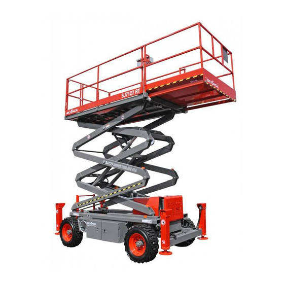
PLATFORM SAFETY LIFTING MECHANISM HYDRAULIC/ ENGINE FUEL TANK TRAY SIDE CABINET HYDRAULIC/ ELECTRIC SIDE CABINET Figure 1-1. SKYJACK SJ-600 Series Work Platform (Model 7027 with powered extension platform option shown) SJ-600 Series Engine Powered SECTION 1, Page 5 June 2001... -
Page 12: Operating Controls Identification 1
SECTION 2 OPERATION Operating Controls Identification Emergency Battery Disconnect Switch The following descriptions are for identification, explanation and locating purposes only. A qualified operator MUST read and completely understand these descriptions before operating this work platform. Procedures for operating this work platform are detailed in the “OPERATING PROCEDURES”... - Page 13 Engine Control Panel (Dual Fuel) Engine Control Panel (Diesel) Figure 2-4A. Engine Control Panel - Ford Gasoline Engine (Shown with Dual Fuel) Figure 2-4B. Engine Control Panel - Kubota Diesel Engine Engine Control Panel - This control station is Engine Control Panel - This control station is attached to the Engine Roll-out at the front of the base.
-
Page 14: Platform Controls
Platform Controls 5. Enable Push-Button - When depressed and Operator’s Control Box held, this push-button switch brings power to the lift or outrigger circuits. On some models, This button must also be held depressed to energize the drive or steer functions. 6. - Page 15 Hydraulic Generator Control (Option) Powered Extension Platform Control Box (Option) Figure 2-6. Hydraulic Generator Control Figure 2-8. Powered Extension Platform Control Box Hydraulic Generator Control - Located on the side of Powered Platform Control Box - This metal control the Operator’s Control Box, this push-button switch station is mounted at the right front of the extension starts the hydraulic generator on the base.
-
Page 16: Identification And Operation Of Safety Devices
Identification And Operation of Base Controls - Manual Safety Bar Safety Devices Fold-Down Guardrail System Figure 2-11. Safety Bar Safety Bar - Designed to support the scissors assembly (when properly positioned), the safety bar MUST be used for inspection and performing maintenance or repairs within the scissors assembly. -
Page 17: Operating Procedures
Operating Procedures Warning Explosion Hazard following descriptions Operating Procedures. A qualified operator MUST read and completely understand these descriptions before Keep flames and sparks away. DO NOT smoke near operating this work platform. batteries. First Aid Set-Up Procedure Immediately flush eyes with cold water if electrolytic acid is splattered into them. -
Page 18: Prestart Checks
Use the Down Switch to lower the platform to OF THIS EQUIPMENT! it’s fully lowered position. Your SKYJACK Model is now ready for use by an authorized, qualified operator who has read and completely understands ALL of Section 2, OPERATION in this manual. - Page 19 Operator Qualifications If the engine is cold, depress and hold the Engine Choke Push-button (Gasoline engines) or depress and hold the Glow Plug Push-button Only trained and authorized persons should use this for 15 to 20 seconds) (Diesel engines) and work platform.
-
Page 20: Shutdown Procedure
Shutdown Procedure To Steer: Select “DRIVE” position with Off/Lift/ Drive Select Key Switch. If equipped, activate and hold the Enable switch (by squeezing the Completely lower the platform. trigger towards the joystick or pressing the control box side mounted push button), then Turn key to “OFF”... -
Page 21: Emergency Lowering System
Emergency Lowering System 2. Emergency Lowering Valve - Pull out and hold the Emergency Lowering Valve plunger, and the platform will gradually lower. Located at the rear of the hydraulic/electric side cabinet, this pull-type valve when used in conjunction with the holding valve manual overrides, allows platform lowering in the event of an emergency or electrical system failure. -
Page 22: Winching And Towing Procedures
Hydraulic Generator (Option) Winching And Towing Procedures To start the hydraulic generator, Ensure the Warning engine is on high throttle by selecting “HIGH” on the “Low/High Throttle Select” switch. Select the “LIFT” position with the “Off/Lift/Drive” key When Towing, DO NOT drive onto a downward slope switch, then depress hydraulic generator push- or brake the towing vehicle rapidly. - Page 23 Later Models: Earlier Models: Figure 2-14B. Parking Brake Release Hand Pump and Quick Brake Valve (Machines With Serial Number 30166 and Below) Figure 2-14A. Parking Brake Release Hand Pump and Brake Valve Plunger (Machines With Serial Number 6 - 7. Parking Brake Release Hand Pump (6) and 30167 and Above) Brake Valve Knob (7) - Located on the brake manifold...
- Page 24 30-10-16.5 OTR Outrigger 70 (482.6)* 75 (517.1) 31-15.5-15 NHS 50 (344.7)* Not Available 31-13.5-15 NHS Consult Skyjack Inc. 30-10-16.5 NHS Solid 31-15.5-15 NHS Urethane 31-13.5-15 NHS Consult Skyjack Inc. Factory preset @ 20°C, Check pressures regularly as tires can lose pressure over time and over different ambient temperatures even under normal conditions.
- Page 25 Table 2-4. Maintenance And Inspection Schedule Daily Weekly Monthly 3 Months 6 Months 12 Months* Engine Fuel leaks Engine oils H & I H & I Engine RPM Fuel filter Belts/Hoses A & C A & C Muffler B, C & J B, C &...
-
Page 26: Section 3 - Systems Component Identification And Schematics
SECTION 3 SYSTEM COMPONENT IDENTIFICATION AND SCHEMATICS TABLE OF CONTENTS SYMBOLS & CHARTS FIGURE 3.1-1. RELAY TERMINAL FUNCTION IDENTIFICATION ..............2 FIGURE 3.1-2. ELECTRICAL SYMBOL CHART ....................3 FIGURE 3.1-3. HYDRAULIC SYMBOL CHART ....................4 HYDRAULIC SYSTEM FIGURE 3.2-1. HYDRAULIC SCHEMATIC Powered Extension Platform ............5 FIGURE 3.2-2. - Page 27 FIGURE 3.1-1. RELAY TERMINAL AND FUNCTION CHART COMMON COMMON COIL COIL COIL COIL GROUND (B-) CONTROL CONTROL CONTROL CONTROL (B-) (B+) (B+) (B-) NORMALLY NORMALLY NORMALLY CLOSED CLOSED CLOSED CONTACT CONTACT CONTACT NORMALLY NORMALLY OPEN OPEN CONTACT CONTACT RELAY NO. RELAY FUNCTION RELAY NO.
- Page 28 FIGURE 3.1-2. ELECTRICAL SYMBOL CHART WIRE CROSSING HOURMETER KEY SWITCH WIRES JOINED LIGHT FOOT SWITCH HYDRAULIC VALVE COIL BATTERY TOGGLE SWITCH PROPORTIONAL HYDRAULIC VALVE GROUND PUSH BUTTON COIL ELECTRIC MOTOR FUSE ROTARY SWITCH CIRCUIT BREAKER HORN LIMIT SWITCH BATTERY CHARGE EMERGENCY CAM OPERATED INDICATOR...
- Page 29 FIGURE 3.1-3. HYDRAULIC SYMBOL CHART VARIABLE LINE CROSSING DISPLACEMENT SHUTTLE VALVE VELOCITY FUSE PUMP SINGLE ACTING ACCUMULATOR, LINE JOINED HAND PUMP GAS CHARGED CYLINDER DOUBLE ACTING HYDRAULIC TANK CUSHION RELIEF VALVE CYLINDER CYLINDER HYDRAULIC PRESSURE PRESSURE DOUBLE ACTING FILTER WITH SWITCH REDUCING VALVE DOUBLE RODDED...
- Page 30 NOTES FIGURE 3.2-1. HYDRAULIC SCHEMATIC - Powered Extension Platform 50017AA Units Index Skyjack Description Part No. Assy. (Ref.) CYLINDER ASSEMBLY, Powered extension platform (Refer to Figure 6-5.) 107396 • KIT, Seal repair 4H-26 103397 VALVE, “Vickers” Platform extend (Earlier models - replace with Hytos)
- Page 31 Parts List FIGURE 3.2-2. HYDRAULIC SCHEMATIC 50016AA SJ-600 Series Engine Powered 112715 SECTION 3, Page 6 June 2001...
- Page 32 FIGURE 3.2-2. HYDRAULIC SCHEMATIC PARTS LIST FIGURE 3.2-2. HYDRAULIC SCHEMATIC PARTS LIST Units Units Description Description Index Skyjack Index Skyjack Part No. Part No. Assy. Assy. 121091 CYLINDER ASSEMBLY, Lift 110460 PUMP , Dual inlet hydraulic .488/.854 (Machines with Kubota diesel engine) Use Part # 110530 for Machines with Serial # 32328 and below.
- Page 33 FIGURE 3.2-3. HYDRAULIC MANIFOLD COMPONENT AND PORT IDENTIFICATION TO HYDRAULIC TO MAIN TO STEER TO BRAKE TO CENTER OIL TANK MANIFOLD CYLINDER DRIVE MANIFOLD TO BRAKE 4H-23A CYLINDER 2H-14B LEFT STEER LIFT VALVE VALVE (shown) 4H-24A RIGHT STEER VALVE AUTO-RESET BRAKE MANIFOLD SYSTEM BLOCK...
- Page 34 FIGURE 3.3-1A. OPERATOR’S CONTROL BOX DIAGRAM - No Options (Machines With Serial Number 32097 and Below) 50018AA SECTION 3, Page 10 SJ-600 Series Engine Powered 112715 June 2001...
- Page 35 FIGURE 3.3-1A. OPERATOR’S CONTROL BOX DIAGRAM - No Options (Machines With Serial Number 32097 and Below) Units Index Skyjack Description Part No. Assy. 103334 CONTROLLER ASSEMBLY, Drive/steer (S7) (For components, refer to Figure 6-9.) 103012 STRIP , Terminal block 114485...
- Page 36 FIGURE 3.3-1B. OPERATOR’S CONTROL BOX DIAGRAM - No Options (Machines With Serial Number 32098 To 33047) 50019AA SECTION 3, Page 12 SJ-600 Series Engine Powered 112715 June 2001...
- Page 37 FIGURE 3.3-1B. OPERATOR’S CONTROL BOX DIAGRAM - No Options (Machines With Serial Number 32098 To 33047) Units Index Skyjack Description Part No. Assy. 103334 CONTROLLER ASSEMBLY, Drive/steer (S7) (For components, refer to Figure 6-9.) 103012 STRIP , Terminal block 114485 CABLE ASSEMBLY, Control box 32 pole male (Ref.)
- Page 38 FIGURE 3.3-1C. OPERATOR’S CONTROL BOX DIAGRAM - No Options (Machines With Serial Numbers From 32048 To 33188) 50020AA SECTION 3, Page 14 SJ-600 Series Engine Powered 112715 June 2001...
- Page 39 FIGURE 3.3-1C. OPERATOR’S CONTROL BOX DIAGRAM - No Options (Machines With Serial Numbers From 32048 To 33188) Units Index Skyjack Description Part No. Assy. 103334 CONTROLLER ASSEMBLY, Drive/steer (S7) (For components, refer to Figure 6-9.) 103012 STRIP , Terminal block...
- Page 40 FIGURE 3.3-1D. OPERATOR’S CONTROL BOX DIAGRAM - No Options (Machines With Serial Number 33189 And Above) 50079AA SECTION 3, Page 16 SJ-600 Series Engine Powered 112715 June 2001...
- Page 41 FIGURE 3.3-1D. OPERATOR’S CONTROL BOX DIAGRAM - No Options (Machines With Serial Number 33189 And Above) Units Index Skyjack Description Part No. Assy. 123995 CONTROLLER ASSEMBLY, Drive/steer (S7) (For components, refer to Figure 6-9.) 103012 STRIP , Terminal block 114485 CABLE ASSEMBLY, Control box 32 pole male (Ref.)
- Page 42 FIGURE 3.3-2A. OPERATOR’S CONTROL BOX DIAGRAM - All Options (Machines With Serial Number 32097 and Below) 50021AA SECTION 3, Page 18 SJ-600 Series Engine Powered 112715 June 2001...
- Page 43 FIGURE 3.3-2A. OPERATOR’S CONTROL BOX DIAGRAM - All Options (Machines With Serial Number 32097 and Below) Units Index Skyjack Description Part No. Assy. 103334 CONTROLLER ASSEMBLY, Drive/steer (S7) (For components, refer to Figure 6-9.) 103012 STRIP , Terminal block 115283...
- Page 44 FIGURE 3.3-2B. OPERATOR’S CONTROL BOX DIAGRAM - All Options (Machines With Serial Number 32098 To 33047) 50022AA SECTION 3, Page 20 SJ-600 Series Engine Powered 112715 June 2001...
- Page 45 FIGURE 3.3-2B. OPERATOR’S CONTROL BOX DIAGRAM - All Options (Machines With Serial Number 32098 To 33047) Units Index Skyjack Description Part No. Assy. 103334 CONTROLLER ASSEMBLY, Drive/steer (S7) (For components, refer to Figure 6-9.) 103012 STRIP , Terminal block 114485 CABLE ASSEMBLY, Control box 32 pole male (Ref.)
- Page 46 FIGURE 3.3-2C. OPERATOR’S CONTROL BOX DIAGRAM - All Options (Machines With Serial Numbers From 32048 To 33188) 50023AA SECTION 3, Page 22 SJ-600 Series Engine Powered 112715 June 2001...
- Page 47 FIGURE 3.3-2C. OPERATOR’S CONTROL BOX DIAGRAM - All Options (Machines With Serial Numbers From 32048 To 33188) Units Index Skyjack Description Part No. Assy. 103334 CONTROLLER ASSEMBLY, Drive/steer (S7) (For components, refer to Figure 6-9.) 103012 STRIP , Terminal block...
- Page 48 FIGURE 3.3-2D. OPERATOR’S CONTROL BOX DIAGRAM - All Options (Machines With Serial Number 33189 And Above) 50080AA SECTION 3, Page 24 SJ-600 Series Engine Powered 112715 June 2001...
- Page 49 FIGURE 3.3-2D. OPERATOR’S CONTROL BOX DIAGRAM - All Options (Machines With Serial Number 33189 And Above) Units Index Skyjack Description Part No. Assy. 123995 CONTROLLER ASSEMBLY, Drive/steer (S7) (For components, refer to Figure 6-9.) 103012 STRIP , Terminal block 114485 CABLE ASSEMBLY, Control box 32 pole male (Ref.)
- Page 50 FIGURE 3.4-1. ELECTRICAL PARTS LIST Units Ref. Skyjack Description Part No. Assy (Ref). ANSI/SIA & CSA Models (Kubota Dual Fuel ) Serial #31801 and Below (Ref.) ANSI/SIA & CSA Models (Kubota Dual Fuel ) Serial #31802 and Above (Ref.) CE Models (Kubota Diesel) (Ref.)
- Page 51 FIGURE 3.4-1. ELECTRICAL PARTS LIST (Continued) Units Ref. Skyjack Description Part No. Assy Parts list continued from the previous page. 103334 CONTROLLER ASSEMBLY, Drive/steer, 123995 CONTROLLER ASSEMBLY, Drive/steer, S7-1 102768 • SWITCH W/ACTUATOR, 2nd Speed, 122869 • SWITCH W/ACTUATOR, 2nd Speed,...
- Page 52 FIGURE 3.4-1. ELECTRICAL PARTS LIST (Continued) Units Ref. Skyjack Description Part No. Assy Parts list continued from the previous page. TPS1 113400 SWITCH, Engine temperature 117880 TILT SWITCH ASSEMBLY 103336 HOUR METER 111623 SWITCH, Vacuum (dual fuel option), 103207 RELAY, 12 Volt DPDT (drive time delay)
- Page 53 FIGURE 3.4-1. ELECTRICAL PARTS LIST (Continued) Units Skyjack Ref. Description Part No. Assy Parts list continued from the previous page. 2H-10A 103613 COIL, 12 Volt (brake lock valve) (Machines with serial number 30166 and below) 2H-13B 103613 COIL, 12 Volt (main lowering valve)
- Page 54 Parts List FIGURE 3.4-2. BASE CONTROL/ELECTRICAL PANEL DIAGRAM (ANSI/SIA and CSA Machines With Serial Number 30985 and Below) FIG3-3 SJ-600 Series Engine Powered 112715 SECTION 3, Page 31 June 2001...
- Page 55 Parts List FIGURE 3.4-3. BASE CONTROL/ELECTRICAL PANEL DIAGRAM (ANSI/SIA and CSA Machines With Serial Number 30986 through 32097) 50174AA SJ-600 Series Engine Powered 112715 SECTION 3, Page 32 June 2001...
- Page 56 Parts List FIGURE 3.4-4. BASE CONTROL/ELECTRICAL PANEL DIAGRAM (ANSI/SIA and CSA Machines With Serial Number 32098 and Above) LP-1050AC SJ-600 Series Engine Powered 112715 SECTION 3, Page 33 June 2001...
- Page 57 Parts List FIGURE 3.4-5. BASE CONTROL/ELECTRICAL PANEL DIAGRAM (CE Machines With Serial Number 30985 and Below) FIG3-4 SJ-600 Series Engine Powered 112715 SECTION 3, Page 34 June 2001...
- Page 58 Parts List FIGURE 3.4-6. BASE CONTROL/ELECTRICAL PANEL DIAGRAM (CE Machines With Serial Number 30986 through 32097) FIG3-2B SJ-600 Series Engine Powered 112715 SECTION 3, Page 35 June 2001...
- Page 59 Parts List FIGURE 3.4-7. BASE CONTROL/ELECTRICAL PANEL DIAGRAM (CE Machines With Serial Number 32098 and Above) LP-1051AA SJ-600 Series Engine Powered 112715 SECTION 3, Page 36 June 2001...
- Page 60 FIGURE 3.4-8. ELECTRICAL INVERTER DIAGRAM 50077AA SJ-600 Series Engine Powered 112715 SECTION 3, Page 37 June 2001...
- Page 61 Parts List FIGURE 3.5-1. ELECTRICAL SCHEMATIC (Machines Equipped With Kubota Dual Fuel Engine and Shown With ANSI/SIA and CSA Options) 600-98 SJ-600 Series Engine Powered 112715 FIGURE 3.5-1. NOTE: To determine the correct electrical schematic or panel diagram that resembles your machine, refer to the “Table Of Contents”...
- Page 62 Parts List FIGURE 3.5-2. ELECTRICAL SCHEMATIC - (Machines Equipped With Kubota Dual Fuel Engine and Shown With ANSI and CSA Options) 600-70 SJ-800 Series Engine Powered 112715 FIGURE 3.5-2. NOTE: To determine the correct electrical schematic or panel diagram that resembles your machine, refer to the “Table Of Contents”...
- Page 63 Parts List FIGURE 3.5-3. ELECTRICAL SCHEMATIC (Machines Equipped With Kubota Diesel Engine and Shown With CE Options) 50024AA SJ-600 Series Engine Powered 112715 FIGURE 3.5-3. NOTE: To determine the correct electrical schematic or panel diagram that resembles your machine, refer to the “Table Of Contents”...
- Page 64 Parts List Machines Equipped With Kubota Dual Fuel Engine and Shown With ANSI and CSA Options FIGURE 3.5-5. ELECTRICAL SCHEMATIC ( 50078AB SJ-600 Series Engine Powered 112715 FIGURE 3.5-5. NOTE: To determine the correct electrical schematic or panel diagram that resembles your machine, refer to the “Table Of Contents”...
- Page 65 Parts List FIGURE 3.5-6. ELECTRICAL SCHEMATIC (Machines Equipped With Kubota Diesel Engine and Shown With CE Options) 50024AB SJ-800 Series Engine Powered 112715 FIGURE 3.5-6. NOTE: To determine the correct electrical schematic or panel diagram that resembles your machine, refer to the “Table Of Contents”...
- Page 66 Parts List Machines Equipped With Kubota Dual Fuel Engine and Shown With ANSI and CSA Options FIGURE 3.5-7. ELECTRICAL SCHEMATIC ( 50083AA SJ-600 Series Engine Powered 112715 FIGURE 3.5-7. NOTE: To determine the correct electrical schematic or panel diagram that resembles your machine, refer to the “Table Of Contents”...
- Page 67 Parts List FIGURE 3.5-8. ELECTRICAL SCHEMATIC (Machines Equipped With Kubota Diesel Engine and Shown With CE Options) 50024AD SJ-800 Series Engine Powered 112715 FIGURE 3.5-8. NOTE: To determine the correct electrical schematic or panel diagram that resembles your machine, refer to the “Table Of Contents”...
- Page 68 SECTION 3 SYSTEM COMPONENT IDENTIFICATION AND SCHEMATICS ADDENDUM TABLE OF CONTENTS ELECTRICAL SYSTEM FIGURE 3A. IMPORTANT INFORMATION ....................Page B FIGURE 3B. REVISED SCHEMATIC (ANSI Models Equipped with Lift/Drive Enable) (Machines with serial #33048 and above) ..Page C FIGURE 3C. REVISED SCHEMATIC (Models Equipped with All Motion Alarm) (Machines with serial #32975 and above) ....
- Page 69 FIGURE 3A - IMPORTANT INFORMATION ***ATTENTION SERVICE TECHNICIAN*** When performing any maintenance, troubleshooting or service to the 600 Series work platform, please note: • The electrical schematic Addendum found in Section 3, Page C must be taken into consideration when working on machines equipped with a “Lift/Drive” Enable switch on the platform control box.
- Page 70 FIGURE 3B. REVISED SCHEMATIC (All Models Equipped With Lift/ Drive Enable) (Machines with serial #33048 and above) SJ-600 Series Engine Powered 112715 SECTION 3, Page C June 2001...
- Page 71 FIGURE 3C. REVISED SCHEMATIC (All Models Equipped With All Motion Alarm) (Machines with serial #32975 and above) SECTION 3, Page D SJ-600 Series Engine Powered 112715 June 2001...
- Page 72 SECTION 4 TROUBLESHOOTING INFORMATION The following pages contain a Table of Troubleshooting information for locating and correcting most service trouble which can develop. Careful inspection and accurate analysis of the systems listed in the Table of Troubleshooting Information will localize the trouble more quickly than any other method. This manual cannot cover all possible troubles and deficiencies that may occur.
- Page 73 TROUBLESHOOTING INFORMATION ELECTRICAL SYSTEM TROUBLE PROBABLE CAUSE REMEDY 5. Platform/base select switch (S10) set 5. Set (S10) to platform position. NO POWER TO to base position. PLATFORM 6. Open or defective platform/base 6. Check switch. Replace if defective. (Machines With Base select switch (S10).
- Page 74 TROUBLESHOOTING INFORMATION ELECTRICAL SYSTEM TROUBLE PROBABLE CAUSE REMEDY 2. Loose or broken wire #05A from 2. Check continuity. Replace if ENGINE WILL NOT off/on switch (S30) to engine start defective. CRANK FROM ENGINE switch (S32). CONTROLS 3. Defective engine start switch (S32). 3.
- Page 75 TROUBLESHOOTING INFORMATION ELECTRICAL SYSTEM TROUBLE PROBABLE CAUSE REMEDY 16. Loose or broken wire #11 from fuel 16. Check continuity. Replace if ENGINE CRANKS BUT valve (2G11) to fuel pump (FP1). defective. WILL NOT START 17. Defective fuel pump (FP1) (Gasoline 17.
- Page 76 TROUBLESHOOTING INFORMATION ELECTRICAL SYSTEM TROUBLE PROBABLE CAUSE REMEDY 1. Loose or broken wire #31A from glow 1. Check continuity. Replace if GLOW PLUGS plug switch (S31) to glow plug relay defective. INOPERATIVE FROM (31ACR). PLATFORM OR ENGINE 2. Loose or broken wire #02 from glow 2.
- Page 77 TROUBLESHOOTING INFORMATION ELECTRICAL SYSTEM TROUBLE PROBABLE CAUSE REMEDY HIGH THROTTLE 7. Loose or broken wire #02 from relay 7. Check continuity. Replace if INOPERATIVE (10BCR2) to base terminal block defective. (Machines Without (TB1). Base Control Box 8. Loose or broken wire #05 from base 8.
- Page 78 TROUBLESHOOTING INFORMATION ELECTRICAL SYSTEM TROUBLE PROBABLE CAUSE REMEDY DRIVE AND STEER 4. Loose or broken wire #12 from 4. Check continuity. Replace if INOPERATIVE platform terminal block to joystick defective. (Continued) controller (S7). 5. Loose or broken wire #10A from base 5.
- Page 79 TROUBLESHOOTING INFORMATION ELECTRICAL SYSTEM TROUBLE PROBABLE CAUSE REMEDY STEER LEFT 1. Defective steer left switch (S7-3) in 1. Check switch. Replace if defective. INOPERATIVE joystick controller (S7). 2. Loose or broken wire #24 from steer 2. Check continuity. Replace if left switch (S7-3) to platform terminal defective.
- Page 80 TROUBLESHOOTING INFORMATION ELECTRICAL SYSTEM TROUBLE PROBABLE CAUSE REMEDY FORWARD DRIVE 3. Loose or broken wire #16 joystick 3. Check continuity. Replace if INOPERATIVE controller (S7) to platform terminal defective. (Continued) block. 4. Loose or broken wire #16 from 4. Check continuity. Replace if platform terminal block to relay defective.
- Page 81 TROUBLESHOOTING INFORMATION ELECTRICAL SYSTEM TROUBLE PROBABLE CAUSE REMEDY SECOND DRIVE SPEED 9. Loose or broken wire #35 from base 9. Check continuity. Replace if INOPERATIVE terminal block to relay (35CR). defective. (Continued) 10. Loose or broken wire #02 from relay 10.
- Page 82 TROUBLESHOOTING INFORMATION ELECTRICAL SYSTEM TROUBLE PROBABLE CAUSE REMEDY HIGH/LOW RANGE 1. Loose or broken wire #12 from key 1. Check continuity. Replace if SPEED INOPERATIVE select switch (S3) to low/high range defective. switch (S29). 2. Defective low/high range switch 2. Check switch. Replace if defective. (S29).
- Page 83 TROUBLESHOOTING INFORMATION ELECTRICAL SYSTEM TROUBLE PROBABLE CAUSE REMEDY UP CIRCUIT 12. Loose or broken wire #02 from relay 12. Check continuity. Replace if INOPERATIVE FROM (14CR) to base terminal block. defective. PLATFORM OR BASE 13. Defective relay (14CR). 13. Check relay. Replace if defective. (Continued) 14.
- Page 84 TROUBLESHOOTING INFORMATION ELECTRICAL SYSTEM TROUBLE PROBABLE CAUSE REMEDY DOWN CIRCUIT 7. Diode (D13) Open. 7. Check diode. Replace if defective. INOPERATIVE FROM 8. Loose or broken wire #13 from diode 8. Check continuity. Replace if PLATFORM OR BASE (D13) to base terminal block. defective.
- Page 85 TROUBLESHOOTING INFORMATION ELECTRICAL SYSTEM TROUBLE PROBABLE CAUSE REMEDY POWERED EXTENSION 3. Loose or broken battery cable #103A 3. Check continuity. Replace if DECK INOPERATIVE from fuse (F2) to contactor (09ACR). defective. (Continued) 4. Defective contactor (09ACR). 4. Check contactor. Replace if defective.
- Page 86 TROUBLESHOOTING INFORMATION ELECTRICAL SYSTEM TROUBLE PROBABLE CAUSE REMEDY HYDRAULIC 1. Key select switch (S3) in drive 1. Turn switch to lift position. GENERATOR position. INOPERATIVE 2. Loose or broken wire #09 from key 2. Check continuity. Replace if select switch (S3) to generator switch defective.
- Page 87 TROUBLESHOOTING INFORMATION HYDRAULIC SYSTEM TROUBLE PROBABLE CAUSE REMEDY ALL FUNCTIONS 1. Hydraulic oil level low. 1. Refill tank to proper level. INOPERATIVE 2. Defective pump (P1). 2. Check pump. Repair or replace if defective. 3. Broken engine to pump coupler. 3.
- Page 88 TROUBLESHOOTING INFORMATION HYDRAULIC SYSTEM TROUBLE PROBABLE CAUSE REMEDY BRAKES WILL NOT 1. Stuck or defective brake feed valve 1. Check valve. Repair or replace if RELEASE (2H30A-2). defective. 2. Stuck or defective brake dump valve 2. Check valve. Repair or replace if (2H30A-1).
- Page 89 SECTION 5 MAINTENANCE AND SERVICE Table Of Contents Description Page No. Operators Responsibility For Maintenance .................... 2 Maintenance And Inspection Schedule ....................2 Owners Annual Inspection Record ......................2 General Maintenance Hints ........................2 Hydraulic System And Component Maintenance And Repair ............... 3 General Specifications ...........................
- Page 90 OPERATOR’S RESPONSIBILITY FOR MAINTENANCE AND INSPECTION MAINTENANCE SCHEDULE Death or injury can result if the work platform is not kept The actual operating environment of the work platform in good working order. Inspection and maintenance governs the use of the maintenance schedule. The should be performed by competent personnel who are inspection points covered in Table 2-4.
- Page 91 For conditions oil of the proper type and viscosity in the causing oil temperatures below -31° F (-35° C) hydraulic reservoir. and above 122° F (50° C) consult Skyjack Inc. Keep all connections tight. SJ-600 Series Engine Powered 112715...
- Page 92 Table 5-1. General Specifications - SJ-600 Series ENGINE POWER - Kubota gasoline/propane 23 Hp Water Cooled (DF-750E) ENGINE POWER - Kubota gasoline 23 Hp Water Cooled (WG-750) ENGINE POWER - Kubota diesel 25.5 Hp Water Cooled (D1105-E) ENGINE POWER - Kubota diesel 19.5 Hp Water Cooled (DH-950) BATTERY 12 Volt, 60 Ampere Hour...
- Page 93 30-10-16.5 OTR Outrigger 70 (482.6)* 75 (517.1) 31-15.5-15 NHS 50 (344.7)* Not Available 31-13.5-15 NHS Consult Skyjack Inc. 30-10-16.5 NHS Solid 31-15.5-15 NHS Urethane 31-13.5-15 NHS Consult Skyjack Inc. Factory preset @ 20 C, Check pressures regularly as tires can lose pressure over time and over different ambient temperatures even under normal conditions.
- Page 94 Brake Adjustment Procedures Place machine on level surface and block wheels to prevent rolling in either direction. Turn Battery disconnect off. Locate brake manifold in hydraulic/electric side cabinet. Depress and turn the red knurled knob on the brake valve counter-clockwise to a fully closed position or depress black knob.
- Page 95 Earlier Models: Warning DO NOT manually disengage the parking brakes if the work platform is on a slope. Later Models: Figure 2-13B. Parking Brake Release Hand Pump and Quick Brake Valve (Machines With Serial Number 30166 and Below) 6 - 7. Parking Brake Release Hand Pump (6) and Brake Valve Knob (7) - Located on the brake manifold in the hydraulic electric side cabinet, this hand operated...
- Page 96 SYSTEM AND LIFT PRESSURE ADJUSTMENTS All adjustments MUST be made with a Calibrated Hydraulic Gauge. Refer to the Serial Number Nameplate located on the rear of the machine for System and Lift Pressure values. SYSTEM RELIEF PRESSURE ADJUSTMENT Locate the Right Steer Hydraulic line at the Main Manifold. (Refer to Hydraulic Manifold Component and Port Identification found in SECTION 3 for location.) Tee in a Calibrated 3000 PSI Gauge into the Right Steer line.
- Page 97 2 SPEED MOTOR ASSEMBLY TOP OF BLOCK Units Skyjack Index Description Part No. Assy. 109311 MOTOR, 2 Speed drive 103623 • VALVE, Series/parallel 115340 • CHECK BALL 103613 • COIL, Series/parallel valve 355113 • MANIFOLD, Motor 115338 • SEAL KIT...
- Page 98 WHEEL BOLT/NUT INSPECTION AND TORQUING PROCEDURE It is necessary to check the torque on all wheel nuts and wheel bolts at pre-delivery, after 8 hours of operation and at weekly intervals using the following procedure: Confirm that each wheel fastener is torqued to 140 ft. lbs. (± 5 ft. lbs.) using a suitable torque wrench of known accuracy.
- Page 99 HOW TO ORDER REPAIR PARTS is, the noun name of the part is listed first, then the 1. Address all orders to your local SKYJACK dealer. modifying description information which serves to 2. Specify model and serial number of the work specifically identify the item.
- Page 100 List Of Illustrations Description Page No. Figure 6-1. Main Platform And Railings ..................4, 6 Figure 6-2. Roll-out Extension Platform Assembly ................. 8 Figure 6-3. Powered Extension Platform Assembly ............... 10, 12 Figure 6-4. Powered Extension Platform Control Box ..............14 Figure 6-5.
- Page 101 List Of Illustrations (Continued) Description Page No. Figure 6-29. Hydraulic Oil Tank Assembly (Serial # 30200 And Above) ........78 Figure 6-30. Hydraulic Oil Tank Assembly (Serial # 30199 And Below) ........79 Figure 6-31. Hydraulic/Electric Cabinet Assembly ..............80, 82 Figure 6-32.
- Page 102 FIGURE 6-1. MAIN PLATFORM AND RAILINGS 16 15 MA-600-01C SECTION 6, Page 4 SJ-600 Series Engine Powered 112715 June 2001...
- Page 103 FIGURE 6-1. MAIN PLATFORM AND RAILINGS Units Description Index Skyjack Part No. Assy. (Ref.) MAIN PLATFORM AND RAILINGS (Machines with Serial # 30302 and above) (X = 58-13/16" inside) (Ref.) MAIN PLATFORM AND RAILINGS (Machines with Serial # 30301 and below) (X = 55-9/16" inside) 115250 •...
- Page 104 FIGURE 6-1. MAIN PLATFORMS AND RAILINGS (continued) Units Description Index Skyjack Part No. Assy. Parts list continued from the previous page. 117277 • HINGE, Spring return (Models with serial # 31275 and above) 103632 • • SCREW, Self-tapping 1/4-14 x 3/4" lg.
- Page 105 FIGURE 6-2. ROLL-OUT EXTENSION PLATFORM ASSEMBLY 22 25 10030AA SECTION 6, Page 8 SJ-600 Series Engine Powered 112715 June 2001...
- Page 106 FIGURE 6-2. ROLL-OUT EXTENSION PLATFORM ASSEMBLY Units Description Index Skyjack Part No. Assy. 111017 WELDMENT, Extension platform 105829 PIN, Roller 3/4" x 2-3/8" 100141 ROLLER, Rear 114998 PAD, Nylon 1-3/4" x 4" lg. 103632 SCREW, Self tapping 1/4" 111078 RAILING, Front...
- Page 107 FIGURE 6-3. POWERED EXTENSION PLATFORM ASSEMBLY 10031AA SECTION 6, Page 10 SJ-600 Series Engine Powered 112715 June 2001...
- Page 108 FIGURE 6-3. POWERED EXTENSION PLATFORM ASSEMBLY Units Description Index Skyjack Part No. Assy. 111017 WELDMENT, Extension platform 105829 • PIN, Roller 3/4" x 2-3/8" 100141 • ROLLER, Rear 114998 PAD, Nylon 1-3/4" x 4" lg. 103632 SCREW, Self tapping 1/4"...
- Page 109 FIGURE 6-3. POWERED EXTENSION PLATFORM ASSEMBLY (continued) Units Description Index Skyjack Part No. Assy. Parts list continued from the previous page. 111586 SPACER, Power unit mounting 111136 ROLLER, Extension platform 107057 PAD, Extension deck slider (Ref.) WELDMENT, Main platform (Refer to Figure 6-1.) 110425 PAD, Slider 1"...
- Page 110 FIGURE 6-4. POWERED EXTENSION PLATFORM CONTROL BOX ASSEMBLY MA-SJII-31B Units Description Index Skyjack Part No. Assy. 115592 CONTROL BOX ASSEMBLY, Powered extension platform (Later models with toggle switch controls) 115481 CONTROL BOX ASSEMBLY, Powered extension platform (Early models with rotary switch controls) 115539 •...
- Page 111 FIGURE 6-5. POWERED EXTENSION PLATFORM CYLINDER ASSEMBLY MA-1000-51 Units Description Index Skyjack Part No. Assy. 113427 CYLINDER ASSEMBLY, 5 Ft. extension platform CYLINDER ASSEMBLY, 5 Ft. extension platform (108728) 106454 • WELDMENT, Cylinder barrel 108723 • GLAND, Cylinder end 103829 •...
- Page 112 FIGURE 6-6. POWERED EXTENSION PLATFORM ELECTRICAL PANEL MA-600-04 Units Description Index Skyjack Part No. Assy. 103012 BLOCK, Terminal 103955 • BOLT, Machine #6-32 x 3/4" lg. 103985 • NUT, Machine #6-32 117325 BREAKER, 15 Amp circuit 111611 PANEL, Powered platform electrical (Ref.)
- Page 113 FIGURE 6-7. POWERED EXTENSION PLATFORM HYDRAULIC HOSE CONNECTIONS MA-800-12 Units Description Index Skyjack Part No. Assy. (Ref.) CYLINDER ASSEMBLY, Powered extension platform (For components, refer to Figure 6-5.) (Ref.) POWER UNIT ASSEMBLY, 12 VDC (For components, refer to Figure 6-3.)
- Page 114 FIGURE 6-8A. CONTROL BOX ASSEMBLY (Used on Machines With Serial Numbers 33189 and Above) For Control Box Label Information, Refer to Figure 6-58. L3F-1037AA SECTION 6, Page 18 SJ-600 Series Engine Powered 112715 June 2001...
- Page 115 FIGURE 6-8A. CONTROL BOX ASSEMBLY (Used on Machines With Serial Numbers 33189 and Above) Units Description Index Skyjack Part No. Assy. 400091 CONTROL BOX ASSEMBLY (ANSI/SIA & CSA and CE) 355128 COVER, Control box bottom 355129 WELDMENT, Control box 112327 •...
- Page 116 FIGURE 6-8A. CONTROL BOX ASSEMBLY (Continued) (Used on Machines With Serial Numbers 33189 and Above) Units Description Index Skyjack Part No. Assy. Parts list continued from the previous page. (Ref.) SWITCH ASSEMBLY, Emergency stop 100149 • WASHER, Flat 102769 • HEAD, Stop switch 103100 •...
- Page 117 FIGURE 6-8B. CONTROL BOX ASSEMBLY (Used on Machines With Serial Numbers 33188 and Below) LP-1056AA SECTION 6, Page 22 SJ-600 Series Engine Powered 112715 June 2001...
- Page 118 FIGURE 6-8B. CONTROL BOX ASSEMBLY (Used on Machines With Serial Numbers 33188 and Below) Units Description Index Skyjack Part No. Assy. 400091 CONTROL BOX ASSEMBLY (ANSI/SIA and CSA) (Consists of items 1 - 14, 24 - 28) (Replaces 114495) 400091 CONTROL BOX ASS’Y (CE)
- Page 119 FIGURE 6-8B. CONTROL BOX ASSEMBLY (Continued) (Used on Machines With Serial Numbers 33188 and Below) Units Description Index Skyjack Part No. Assy. Parts list continued from the previous page. (Ref.) • SWITCH ASSEMBLY, Key select 102753 • • HEAD, 3-Position key select 103100 •...
- Page 120 FIGURE 6-8B. CONTROL BOX ASSEMBLY (Continued) (Used on Machines With Serial Numbers 33188 and Below) Units Description Index Skyjack Part No. Assy. Parts list continued from the previous page. 113451 • BRACKET, Terminal block mount 114373 • SWITCH, Torque toggle (serial no. 30175 and above) 111181 •...
- Page 121 FIGURE 6-9A. DRIVE/STEER CONTROLLER ASSEMBLY (Used on Machines With Serial Numbers 33189 and Above) 27 26 S3F-1049AA SECTION 6, Page 28 SJ-600 Series Engine Powered 112715 June 2001...
- Page 122 FIGURE 6-9A. DRIVE/STEER CONTROLLER ASSEMBLY (Used on Machines With Serial Numbers 33189 and Above) Units Description Index Skyjack Part No. Assy. 123995 CONTROLLER ASSEMBLY, Enable Joystick 122849 • HANDLE ASSEMBLY 122873 • • LEVER, Trigger 122872 • • SWITCH, Push button 122874 •...
- Page 123 FIGURE 6-9B. DRIVE/STEER CONTROLLER ASSEMBLY (Used on Machines With Serial Numbers 33188 and Below) MA-SJM-13A Units Description Index Skyjack Part No. Assy. 103334 CONTROLLER ASSEMBLY, Drive/steer 105735 • CAP , Elastic 105734 • ACTUATOR, Rocker 105733 • SWITCH, Directional 105738 •...
- Page 124 FIGURE 6-10. SCISSOR ARM ASSEMBLY 4 38 10310AA SECTION 6, Page 32 SJ-600 Series Engine Powered 112715 June 2001...
- Page 125 FIGURE 6-10. SCISSOR ARM ASSEMBLY Units Description Index Skyjack Part No. Assy. 109795 ARM ASSEMBLY, 1st Inner 109798 ARM, 1st Outer RH 111754 ARM, 1st Outer LH 109796 ARM ASSEMBLY, 2nd Inner 109799 ARM, 2nd Outer RH 110790 ARM, 2nd Outer LH...
- Page 126 FIGURE 6-10. SCISSOR ARM ASSEMBLY (continued) Units Description Index Skyjack Part No. Assy. Parts list continued from the previous page. 111931 CORD ASSEMBLY, Holding valve 103256 • CORD, 18/2 x 269" lg. 117518 • CONNECTOR, Clear 111135 BUMPER, Scissor arm 2-1/2" x 1-1/16" thk.
- Page 127 Description Index Skyjack Part No. Assy. Parts list continued from the previous page. 124642 SPACER (Contact Skyjack Before Ordering if Machine Has Serial #33435 or Above) 355153 TUBING, 1.38” O.D. x 1.26” I.D. 355154 BUSHING, 2828 355116 ONTARIO CLAMP OPTION 752729 CLAMP , 1”...
- Page 128 FIGURE 6-11. LIFT CYLINDER ASSEMBLY MA-600-09 SECTION 6, Page 38 SJ-600 Series Engine Powered 112715 June 2001...
- Page 129 FIGURE 6-11. LIFT CYLINDER ASSEMBLY Units Description Skyjack Index Part No. Assy. 121091 CYLINDER ASSEMBLY, Lift 110530 CYLINDER ASSEMBLY, Lift Used on Machines with Serial # 32328 and Below. 121094 • WELDMENT, Cylinder barrel A 113420 • WELDMENT, Cylinder barrel B 111094 •...
- Page 130 FIGURE 6-12. SCISSOR ARM HYDRAULIC HOSE CONNECTIONS MA-600-06 Units Description Index Skyjack Part No. Assy. (Ref.) CYLINDER ASSEMBLY, Lift (For components, refer to Figure 6-11.) 114578 FITTING, Elbow 90° #6orb-#6 110666 BLOCK, Lift manifold 103861 BOLT, Hex-hd 1/4-20 x 2" lg.
- Page 131 FIGURE 6-13. BASE, AXLES, AND WHEELS 16 17 MA-600-28B SECTION 6, Page 42 SJ-600 Series Engine Powered 112715 June 2001...
- Page 132 FIGURE 6-13. BASE, AXLES AND WHEELS FIGURE 6-13. BASE, AXLES AND WHEELS Units Units Description Description Skyjack Skyjack Index Index Part No. Part No. Assy. Assy. 112928 WELDMENT, Base (standard) 111612L WHEEL/TIRE ASSEMBLY (standard) 100309 BUSHING (30 x 9.5 x 16.5 6 ply air filled)
- Page 133 FIGURE 6-14. BASE HYDRAULIC HOSE CONNECTIONS (Machines With Serial # 32273 and Above) 10261AA SECTION 6, Page 44 SJ-600 Series Engine Powered 112715 June 2001...
- Page 134 NOTES FIGURE 6-14. BASE HYDRAULIC HOSE CONNECTIONS (Machines With Serial # 32273 and Above) Units Description Index Skyjack Part No. Assy. (Ref.) COVER, Hydraulic tank (For Components, Refer to Figure 6-29) (Ref.) CYLINDER ASS’Y, Disc brake (For Components, Refer to Figure 6-18)
- Page 135 FIGURE 6-15. BASE HYDRAULIC HOSE CONNECTIONS (Machines With Serial #’s 30170 through 32272) MA-600-32 SECTION 6, Page 46 SJ-600 Series Engine Powered 112715 June 2001...
- Page 136 NOTES FIGURE 6-15. BASE HYDRAULIC HOSE CONNECTIONS (Machines With Serial # 30170 through 32272) Units Description Skyjack Index Part No. Assy. (Ref.) COVER, Hydraulic tank (For Components, Refer to Figure 6-29 & 6-30) (Ref.) CYLINDER ASS’Y, Disc brake (For Components, Refer to Figure 6-18)
- Page 137 FIGURE 6-16. BASE HYDRAULIC HOSE CONNECTIONS (Machines With Serial # 30169 and Below) Hydraulic Tank Cover Hydraulic Motor Disk Brake Cylinder Hydraulic Pump Motion Control Valve Cushion Cylinder Main Manifold Quick Brake Manifold Steer Cylinder MA-600-21 SECTION 6, Page 48 SJ-600 Series Engine Powered 112715 June 2001...
- Page 138 FIGURE 6-16. BASE HYDRAULIC HOSE CONNECTIONS FIGURE 6-16. BASE HYDRAULIC HOSE CONNECTIONS (Machines With Serial # 30169 and Below) (Machines With Serial # 30169 and Below) Units Units Description Skyjack Description Index Skyjack Index Part No. Part No. Assy. Assy.
- Page 139 NOTES FIGURE 6-17. DISC BRAKE ASSEMBLY MA-800-06 SECTION 6, Page 50 SJ-600 Series Engine Powered 112715 June 2001...
- Page 140 FIGURE 6-17. DISC BRAKE ASSEMBLY Units Description Index Skyjack Part No. Assy. (Ref.) CYLINDER ASSEMBLY, Disc brake (For components, refer to Figure 6-18.) 109579 SPACER, Cylinder mounting 109599 CLEVIS, Rod end 1/2-20 109598 NUT, Jam 1/2-20 109600 PIN, Clevis 109601...
- Page 141 FIGURE 6-18. DISC BRAKE CYLINDER ASSEMBLY L1F-1003AA Units Description Skyjack Index Part No. Assy. 120412 CYLINDER ASSEMBLY, Disc brake 120631 • ROD, Brake cylinder 109597 • WIPER, Brake rod 120409 • GLAND, Front end 109573 • SPACER, Stroke limit 109604 •...
- Page 142 FIGURE 6-19A. STEER CYLINDER ASSEMBLY (Machines With Serial # 32328 and Below) MA-600-07A Units Description Index Skyjack Part No. Assy. 113356 CYLINDER ASSEMBLY, Steer (2WD/4WD) 113347 • ROD, Steering 113350 • SEAL, Steering rod 107934 • O-RING, Gland 112496 • GLAND 113349 •...
- Page 143 FIGURE 6-19B. STEER CYLINDER ASSEMBLY L1F-1055AA Units Description Skyjack Index Part No. Assy. 121086 CYLINDER ASSEMBLY, Steer (2WD/4WD) 113347 • ROD, Steering 113350 • SEAL, Steering rod 120438 • O-RING, Gland 120401 • GLAND, Front end 113349 • WIPER, Rod 103513 •...
- Page 144 FIGURE 6-20. FRONT IDLE AXLE ASSEMBLY (For 2-Wheel Drive Machines) MA-800-08A SECTION 6, Page 56 SJ-600 Series Engine Powered 112715 June 2001...
- Page 145 FIGURE 6-20. FRONT IDLE AXLE ASSEMBLY (For 2-Wheel Drive Machines) Units Description Index Skyjack Part No. Assy. 112031 AXLE ASSEMBLY, Front idle 111585 • WELDMENT, Front idle axle 111756 • WELDMENT, Spindle arm RH 111755 • WELDMENT, Spindle arm LH 100309 •...
- Page 146 FIGURE 6-21. FRONT AXLE HARDWARE ASSEMBLY (4WD) 10266AA SECTION 6, Page 58 SJ-600 Series Engine Powered 112715 June 2001...
- Page 147 FIGURE 6-21. FRONT AXLE HARDWARE ASSEMBLY (4WD) Units Description Index Skyjack Part No. Assy. (Ref.) SHAFT ASSEMBLY, Front drive (For Components, Refer to Figure 6-23 or 6-24) (Ref.) AXLE, Front (For Components, Refer to Figure 6-22) 109775 BRACKET, Steering arm 300689 •...
- Page 148 FIGURE 6-22. FRONT AXLE ASSEMBLY (4WD) 17 1 TIF-1028AC SECTION 6, Page 60 SJ-600 Series Engine Powered 112715 June 2001...
- Page 149 FIGURE 6-22. FRONT AXLE ASSEMBLY (4WD) Units Description Skyjack Index Part No. Assy. 111583 MODIFIED AXLE ASSEMBLY, Front drive 103337 • AXLE ASSEMBLY, Front drive (DANA 60B) • • HOUSING W/BEARING CAPS, Front drive axle 113927 • • DRIVE GEAR AND PINION SET 113928 •...
- Page 150 FIGURE 6-22. FRONT AXLE ASSEMBLY (4WD) (Continued) Units Description Skyjack Index Part No. Assy. Parts list continued from the previous page. 113907 • • CAP , Hub 113935 • • DIFFERENTIAL ASSEMBLY 113936 • • • GEAR SET, Internal differential 113937 •...
- Page 151 FIGURE 6-23A. CENTER DRIVE AND DRIVE SHAFTS (Haessler Drive Serial # 1691 and Above) L1F-1142AA SECTION 6, Page 64 SJ-600 Series Engine Powered 112715 June 2001...
- Page 152 FIGURE 6-23A. CENTER DRIVE AND DRIVE SHAFTS (Haessler Drive Serial # 1691 and Above) Units Description Index Skyjack Part No. Assy. 900550 CENTER DRIVE Assembly 121629 CAP , Output Shaft (2WD) 900328 • SEAL, Lip 900408 • HOUSING, Transfer Case, Front 900080 •...
- Page 153 FIGURE 6-23B. CENTER DRIVE AND DRIVE SHAFTS (Haessler Drive Serial # 1690 and Below) L1F-1144AA SECTION 6, Page 66 112715 SJ-600 Series Engine Powered June 2001...
- Page 154 FIGURE 6-23B. CENTER DRIVE AND DRIVE SHAFTS (Haessler Drive Serial # 1690 and Below) Units Description Index Skyjack Part No. Assy. 900550 CENTER DRIVE Assembly 121629 CAP , Output Shaft (2WD) 900329 • BOLT, M8X1.25X15 900328 • SEAL, Lip 900427 •...
- Page 155 FIGURE 6-24. CENTER DRIVE AND DRIVE SHAFTS (Serial # 32272 and Below) 4 Wheel Drive Machines Only MA-800-02 SECTION 6, Page 68 SJ-600 Series Engine Powered 112715 June 2001...
- Page 156 FIGURE 6-24. CENTER DRIVE AND DRIVE SHAFTS (Serial # 32272 and Below) Units Description Index Skyjack Part No. Assy. 110441 WELDMENT, Center drive box 108686 COVER, Chain upper 103887 • BOLT, Hex-hd 5/16-18 x 3/4” lg. 108688 COVER, Chain lower 103855 •...
- Page 157 FIGURE 6-24. CENTER DRIVE AND DRIVE SHAFTS (Serial # 32272 and Below) Units Description Index Skyjack Part No. Assy. Parts list continued from the previous page. 110456 SPROCKET, Center drive (14T) 110522 SPROCKET, Center driven (26T) (Used on early machines) (See NOTE)
- Page 158 FIGURE 6-25. REAR DRIVE AXLE ASSEMBLY MA-800-44 SECTION 6, Page 72 SJ-600 Series Engine Powered 112715 June 2001...
- Page 159 FIGURE 6-25. REAR DRIVE AXLE ASSEMBLY Units Description Index Skyjack Part No. Assy. 111589 AXLE ASSEMBLY, Rear drive (DANA #60A) (Consists of items 1 thru 29) • HOUSING W/BEARING CAPS, Rear drive axle 113938 • DRIVE GEAR AND PINION ASSEMBLY 113939 •...
- Page 160 FIGURE 6-26. FUEL TANK/HYDRAULIC OIL TANK CABINET ASSEMBLY MA-600-10A Units Description Index Skyjack Part No. Assy. 114309 WELDMENT, Fuel tank/hydraulic oil tank cabinet 112014 DOOR, Fuel tank access 103628 • SEAL, Door (72-3/4” total) 101541 • HANDLE W/LOCK, Recessed 111944 •...
- Page 161 FIGURE 6-27. FUEL TANK ASSEMBLY - Gasoline Engines MA-600-11B Units Description Index Skyjack Part No. Assy. 111134 TANK ASSEMBLY, Fuel (Consists of items 1 and 2) (Ref.) • WELDMENT, Fuel tank 113848 • CAP , Filler w/spring 113399 VENT, Breather (Later models up serial #. 31274) 114723 •...
- Page 162 FIGURE 6-28. FUEL TANK ASSEMBLY - Diesel Engines MA-600-12B SECTION 6, Page 76 SJ-600 Series Engine Powered 112715 June 2001...
- Page 163 FIGURE 6-28. FUEL TANK ASSEMBLY - Diesel Engines Units Description Index Skyjack Part No. Assy. 111134 TANK ASSEMBLY, Fuel (Consists of items 1 and 2) (Ref.) • WELDMENT, Fuel tank 113848 • CAP , Filler w/spring 113399 VENT, Breather (Later models up serial # 31274) 114723 •...
- Page 164 FIGURE 6-29. HYDRAULIC OIL TANK ASSEMBLY (Serial # 30200 And Above) MA-600-60 Units Description Skyjack Index Part No. Assy. (Ref.) TANK ASSEMBLY, Hydraulic oil 114315 • WELDMENT, Hydraulic oil tank 114307 • COVER W/SUCTION PIPE, Hydraulic tank 116193 • • SCREW, Machine #10-32 x 1/2” lg.
- Page 165 FIGURE 6-30. HYDRAULIC OIL TANK ASSEMBLY (Serial # 30199 And Below) MA-600-13 Units Description Index Skyjack Part No. Assy. (Ref.) TANK ASSEMBLY, Hydraulic oil 113319 • WELDMENT, Hydraulic oil tank 113318 • COVER W/SUCTION PIPE, Hydraulic tank 103964 • • SCREW, Machine #10-32 x 1/4” lg.
- Page 166 FIGURE 6-31. HYDRAULIC/ELECTRIC CABINET ASSEMBLY MA-600-29B SECTION 6, Page 80 SJ-600 Series Engine Powered 112715 June 2001...
- Page 167 FIGURE 6-31. HYDRAULIC/ELECTRIC CABINET ASSEMBLY Units Description Index Skyjack Part No. Assy. 114146 WELDMENT, Hydraulic/electric cabinet 111152 DOOR, Hydraulic component access 103628 • SEAL, Foam (72-3/4” total) 111153 DOOR, Electrical panel access 103628 • SEAL, Foam (72-3/4” total) 116052 LANYARD, Door stop 18” lg. (Replaces 104104) 103980 •...
- Page 168 FIGURE 6-31. HYDRAULIC/ELECTRIC CABINET ASSEMBLY (Continued) Units Description Index Skyjack Part No. Assy. Parts list continued from the previous page. 119726 SWITCH, Power off/on (Replaces 102601) 105600 BOOT, Switch terminal (Ref.) CABLE ASSEMBLY, Battery to power switch 104533 • CABLE, #2 Battery...
- Page 169 FIGURE 6-32. HYDRAULIC/ELECTRIC CABINET HYDRAULIC HOSE CONNECTIONS (Machines With Serial # 30167 and Above) MA-600-65 Units Description Index Skyjack Part No. Assy. (Ref.) MANIFOLD ASSEMBLY, Main (Refer to Figure 6-36, 6-37.) (Ref.) VALVE ASSEMBLY, Auto reset (Refer to Figure 6-34.)
- Page 170 FIGURE 6-33. HYDRAULIC/ELECTRIC CABINET HYDRAULIC HOSE CONNECTIONS MA-600-14 Units Description Index Skyjack Part No. Assy. (Ref.) MANIFOLD ASSEMBLY, Main (Refer to Figure 6-36, 6-37.) (Ref.) VALVE ASSEMBLY, Quick brake (Refer to Figure 6-35.) 103137 MANIFOLD, Manual lowering 107271 VALVE, Manual lowering 101451 ORIFICE, Lowering .067 I.D.
- Page 171 FIGURE 6-34. AUTO RESET BRAKE MANIFOLD ASSEMBLY (Machines With Serial # 30167 & Above) MA-600-33 Units Description Index Skyjack Part No. Assy. 111943 MANIFOLD, Auto reset brake 110554 FITTING, Run tee #8orb-#8-#8 102659 FITTING, Connector #8orb-#8 102626 VALVE, N.O. (brake)
- Page 172 FIGURE 6-35. QUICK BRAKE MANIFOLD ASSEMBLY (Machines With Serial # 30166 & Below) MA-800-23 Units Description Index Skyjack Part No. Assy. (Ref.) MANIFOLD ASSEMBLY, Quick brake (Order components) 110643 • BLOCK, Brake manifold 104437 • PLUG, Hex-soc #6orb 110652 • PUMP , Hand 102659 •...
- Page 173 FIGURE 6-36. MAIN MANIFOLD ASSEMBLY (Machines With Serial # 30208 and Above) 10237AA SECTION 6, Page 88 SJ-600 Series Engine Powered 112715 June 2001...
- Page 174 FIGURE 6-36. MAIN MANIFOLD ASSEMBLY (Machines With Serial # 30208 and Above) Units Description Index Skyjack Part No. Assy. 114366 MANIFOLD ASSEMBLY, Main (Consists of items 1 thru 22) 114178 • Block, Main manifold 101446 BOLT, Stud 5/16” - 18 x 1 1/2” lg.
- Page 175 FIGURE 6-37. MAIN MANIFOLD ASSEMBLY (Machines With Serial # 30207 and Below) MA-600-16A SECTION 6, Page 90 SJ-600 Series Engine Powered 112715 June 2001...
- Page 176 FIGURE 6-37. MAIN MANIFOLD ASSEMBLY (Machines With Serial # 30207 and Below) Units Description Index Skyjack Part No. Assy. 110586 MANIFOLD ASSEMBLY, Main (Consists of items 1 thru 20) 108009 • BLOCK, Main manifold 103397 • VALVE ASSEMBLY, 12 Volt spool (steer) 107440 •...
- Page 177 FIGURE 6-38. CUSHION CYLINDER ASSEMBLY L1F-1080AA Units Description Index Skyjack Part No. Assy. 107752 CYLINDER, Cushion 104660 FITTING, Tee #6orb-#6-#6 106554 FITTING, Reducer #6orb-#4 103245 FITTING, Tee #4 - #4 - #4 103322 FITTING, Reducer #6 - #4 103615 MANIFOLD, Free-wheeling valve 112218 VALVE, N.O.
- Page 178 FIGURE 6-39. MOTION CONTROL VALVE ASSEMBLY MA-600-62 Units Description Index Skyjack Part No. Assy. 110434 VALVE ASSEMBLY, Motion control 110554 FITTING, Run tee #8orb-#8-#8 102659 FITTING, Connector #8orb-#8 SJ-600 Series Engine Powered 112715 SECTION 6, Page 93 June 2001...
- Page 179 FIGURE 6-40. BASE CONTROL/ELECTRICAL PANEL ASSEMBLY (Machines With Serial # 30986 and Above) 16 28 MA-600-63 SECTION 6, Page 94 SJ-600 Series Engine Powered 112715 June 2001...
- Page 180 FIGURE 6-40. BASE CONTROL/ELECTRICAL PANEL ASSEMBLY (Machines With Serial # 30986 and Above) Units Description Skyjack Index Part No. Assy. 400063 PANEL ASSEMBLY, Electrical (ANSI/SIA and CSA) 400064 PANEL ASSEMBLY, Electrical (CE) 111920 • PANEL, Base control/electrical 400092 • CABLE ASSEMBLY, Panel wiring (ANSI/SIA and CSA) 117102 •...
- Page 181 FIGURE 6-41. BASE CONTROL/ELECTRICAL PANEL ASSEMBLY (Machines With Serial # 30985 & Below) 16 28 MA-600-25 SECTION 6, Page 96 SJ-600 Series Engine Powered 112715 June 2001...
- Page 182 FIGURE 6-41. BASE CONTROL/ELECTRICAL PANEL ASSEMBLY (Machines With Serial # 30985 & Below) Units Description Skyjack Index Part No. Assy. 111920 PANEL, Base control/electrical 112011 CABLE ASSEMBLY, Panel wiring (North America) 113223 CABLE ASSEMBLY, Panel wiring (Europe) 117104 CABLE ASSEMBLY, Engine wiring 8 pole 103318 •...
- Page 183 FIGURE 6-41. BASE CONTROL/ELECTRICAL PANEL ASSEMBLY (Continued) (Machines With Serial # 30985 & Below) Units Description Skyjack Index Part No. Assy. Parts list continued from the previous page. (Ref.) SWITCH ASSEMBLY, Down push-button 102851 • HEAD, Push-button switch 103100 • BASE, Contact 103141 •...
- Page 184 FIGURE 6-42. ENGINE ROLL-OUT TRAY ASSEMBLY (Machines With Serial # 30419 and Above) L1F-1158AC SECTION 6, Page 100 SJ-600 Series Engine Powered 112715 June 2001...
- Page 185 FIGURE 6-42. ENGINE ROLL-OUT TRAY ASSEMBLY (Machines With Serial # 30419 and Above) Units Description Skyjack Index Part No. Assy. (Ref.) TRAY ASSEMBLY, Engine roll-out (Order components) 115585 WELDMENT, Engine roll-out tray 111351 ROLLER, Engine tray 112725 GUARD, Engine Front 114217 •...
- Page 186 FIGURE 6-43. ENGINE ROLL-OUT TRAY ASSEMBLY (Machines With Serial # 30418 and Below) MA-600-23 SECTION 6, Page 102 SJ-600 Series Engine Powered 112715 June 2001...
- Page 187 FIGURE 6-43. ENGINE ROLL-OUT TRAY ASSEMBLY (Machines With Serial # 30418 and Below) Units Description Skyjack Index Part No. Assy. (Ref.) TRAY ASSEMBLY, Engine roll-out (Order components) 112794 WELDMENT, Engine roll-out tray 111351 ROLLER, Engine tray 112725 GUARD, Engine front 103232 PIN, Clevis 1/2”...
- Page 188 FIGURE 6-44. ENGINE CONTROL PANEL - Kubota Dual Fuel (Serial # 31802 and Above) 9 10 MA-600-75 Units Description Index Skyjack Part No. Assy. 355063 ENGINE ELECTRICAL ASSEMBLY, Dual fuel 114194 • PANEL, Engine control front 102572 • SWITCH, Engine off/on 103731 •...
- Page 189 FIGURE 6-45. ENGINE CONTROL PANEL - Kubota Gasoline/Dual Fuel Engines LATER EARLY MODELS MODELS CURRENT MODELS MA-600-20A Units Description Skyjack Index Part No. Assy. 400078 HARNESS ASSEMBLY, Dual fuel (not shown) 400079 HARNESS ASSEMBLY, Gasoline (not shown) 101990 PANEL, Engine control (Early models)
- Page 190 Later Early Models Models Current Models MA-600-19A Units Description Index Skyjack Part No. Assy. 400080 ENGINE ELECTRICAL HARNESS ASSEMBLY, Diesel (not shown) 102921 • • DIODE, 6 Amp (Ref.) • HARNESS, Engine wiring 119134 • • KIT, 12 Pole receptacle connector (mates with #119135 plug) 102572 •...
- Page 191 FIGURE 6-47. ENGINE AND RELATED PARTS - Kubota Dual Fuel Engine L1F-1164AA SECTION 6, Page 108 SJ-600 Series Engine Powered 112715 June 2001...
- Page 192 FIGURE 6-47. ENGINE AND RELATED PARTS - Kubota Dual Fuel Engine Units Description Skyjack Index Part No. Assy. 400062 ENGINE ASS’Y, Kubota dual fuel 355061 • ENGINE, Kubota dual fuel (#DF-750E) Use Engine #102840 for Machines with Serial # 31801 and Below.
- Page 193 FIGURE 6-47. ENGINE AND RELATED PARTS - Kubota Dual Fuel Engine Units Description Index Skyjack Part No. Assy. Parts list continued from the previous page. 103156 • FITTING, Connector 300798 • FILTER, Bulkhead 103164 • FITTING, Elbow 90° 300799 • VALVE, Relief 102519 •...
- Page 194 FIGURE 6-48. ENGINE AND RELATED PARTS - Kubota Gasoline Engine Earlier Models Later Models Gasoline Engines Dual Fuel Engines Models with Serial Number 31801 and below MA-600-26A SECTION 6, Page 112 SJ-600 Series Engine Powered 112715 June 2001...
- Page 195 FIGURE 6-48. ENGINE AND RELATED PARTS - Kubota Gasoline Engine Units Description Index Skyjack Part No. Assy. (Ref.) ENGINE ASS’Y, Kubota gasoline (Current models) (Consists of items 1,5,8 - 10,19,26 - 40, 48 - 50) (Ref.) ENGINE ASS’Y, Kubota gasoline (Later models) (Consists of items 1 thru 13 and 15 thru 28) (Ref.)
- Page 196 FIGURE 6-48. ENGINE AND RELATED PARTS - Kubota Gasoline Engine Units Description Index Skyjack Part No. Assy. Parts list continued from the previous page. 101982 • BRACKET, Throttle solenoid 101860 • LINKAGE, Solenoid 1/2” diameter 109019 • LINK, Throttle 111427 •...
- Page 197 FIGURE 6-49. PROPANE TANK MOUNTING AND CONNECTION 10263AC SECTION 6, Page 116 SJ-600 Series Engine Powered 112715 June 2001...
- Page 198 FIGURE 6-49. PROPANE TANK MOUNTING AND CONNECTION Units Description Index Skyjack Part No. Assy. 400010 LADDER ASSEMBLY, Propane 111628 • LADDER WELDMENT, Propane 101297 • BOLT, Hex-hd. 3/8-16 x 1-1/4” lg. 103999 • WASHER, Lock 3/8 103472 • WASHER, Flat 3/8 114212 •...
- Page 199 FIGURE 6-50. DUAL FUEL SYSTEM - Kubota Gasoline Engine 18 19 20 Earlier Models Models with Serial Number 31801 and below 18 19 20 MA-600-18 SECTION 6, Page 118 SJ-600 Series Engine Powered 112715 June 2001...
- Page 200 FIGURE 6-50. DUAL FUEL SYSTEM - Kubota Gasoline Engine Units Description Index Skyjack Part No. Assy. 103028 TANK W/COUPLING, 33 Lb. Propane 103006 COUPLING, Quick attach LPG 103159 FITTING, Elbow 45° (brass) 103095 HOSE ASSEMBLY, LPG 24” lg. 103156 FITTING, Connector (brass)
- Page 201 FIGURE 6-51. ENGINE AND RELATED PARTS - Kubota Diesel Engine (Serial Number 31252 and above) MA-600-67 SECTION 6, Page 120 SJ-600 Series Engine Powered 112715 June 2001...
- Page 202 FIGURE 6-51. ENGINE AND RELATED PARTS - Kubota Diesel Engine (Serial Number 31252 and above) Units Description Skyjack Index Part No. Assy. 400061 ENGINE ASSEMBLY, Kubota diesel (Current models) (Consists of items 1,3 thru 18) 112696 • ENGINE, Kubota diesel (D1105-E) 355014 •...
- Page 203 FIGURE 6-52. ENGINE AND RELATED PARTS - Kubota Diesel Engine (Serial Number 31251 and below) MA-600-27A SECTION 6, Page 122 SJ-600 Series Engine Powered 112715 June 2001...
- Page 204 FIGURE 6-52. ENGINE AND RELATED PARTS - Kubota Diesel Engine (Serial Number 31251 and below) Units Description Index Skyjack Part No. Assy. (Ref.) ENGINE ASSEMBLY, Kubota diesel (Consists of items 1,4,5,8,10,12,26 thru 35) (Current models) (Ref.) ENGINE ASSEMBLY, Kubota diesel (Consists of items 1 thru 12) (Later models) (Ref.)
- Page 205 FIGURE 6-53. BASE CONTROL BOX OPTION MA-SJII-32A Units Description Index Skyjack Part No. Assy. (Ref.) BASE CONTROL BOX ASSEMBLY (Later models with toggle up/down switch) (Ref.) BASE CONTROL BOX ASSEMBLY (Early models with rotary up/down switch) 115538 • BOX, Base control,...
- Page 206 FIGURE 6-54. AC OUTLET ON PLATFORM OPTION L2F-1015AA Units Description Index Skyjack Part No. Assy. 400067 AC OUTLET ON PLATFORM 109700 • BOX, G.F.I. Receptacle 109699 • PLATE, Weatherproof cover 109698 • RECEPTACLE, 125V G.F.I. 104208 • PLUG, 3-Prong male, 15A/125V 103035 •...
- Page 207 FIGURE 6-55. 3500 WATT HYDRAULIC GENERATOR OPTION - Generator, Oil Cooler, and Mounting 10314AA Units Description Index Skyjack Part No. Assy. 106216 GENERATOR, 3500W Hydraulic 113875 • PUMP , Hydraulic 106673 • COUPLING, Pump 1/2” 103026 • SPIDER, Coupling 113876 •...
- Page 208 FIGURE 6-56. 3500 WATT HYDRAULIC GENERATOR OPTION - Hydraulic Hose Connections 14 15 MA-800-38A Units Description Index Skyjack Part No. Assy. (Ref.) PUMP , Hydraulic generator (Refer to Figure 6-55) 102374 FITTING, Connector #8orb-#8 103294 FITTING, Reducer #10orb-#8P 103215 FITTING, Hose barb...
- Page 209 FIGURE 6-57. SCISSOR GUARD OPTION 10042AA SECTION 6, Page 128 SJ-600 Series Engine Powered 112715 June 2001...
- Page 210 FIGURE 6-57. SCISSOR GUARD OPTION Units Description Index Skyjack Part No. Assy. 115505 FRAME, LH lwr guard Use Part #111658 for Machines with Serial # 30418 and below. 115504 FRAME, RH lwr guard Use Part #111657 for Machines with Serial # 30418 and below.
- Page 211 FIGURE 6-58. LABELS AND NAMEPLATES Rear Of Machine 60 59 Left Side View Of Machine Plate On Front Railing Front View Of Extension Platform Safety Plate On Front Railing Engine Control Panel 26 27 Main Base Control Box Control Box Fuel/Hydraulic Oil Cabinet Lift Cylinder...
- Page 212 • LABEL, Clear (on scissor arm) 109985 • LABEL, Annual inspection 108666 • LABEL, Replacement parts 108946 • LABEL, SKYJACK (small) (21-1/2” wide) 102632 • LABEL, SKYJACK (medium) (26” wide) 105983 • LABEL, Power off/on 105352 • LABEL, Horn (Control box) 102961 •...
- Page 213 LABEL, Generator off/on (Machines with Hydraulic Generator Option) (Ref.) NAMEPLATE, Serial # (Consult factory) 102975 STRIPE, Warning (648” roll) 102631 LABEL, SKYJACK large (36” wide) (Machines with extension platform) 114378 LABEL, Recommended hydraulic oil 114252 LABEL, California Proposition 65 (Only on machines sold in California)
- Page 214 CALIFORNIA Proposition 65 Warning. Diesel engine exhaust and some of its constituents are known to the State of California to cause cancer, birth defects, other reproductive harm. SECTION 6, Page 134 SJ-600 Series Engine Powered 112715 June 2001...
- Page 216 Reliable lift solutions by people who care. www.skyjack.com...
Need help?
Do you have a question about the SJ-7027 and is the answer not in the manual?
Questions and answers