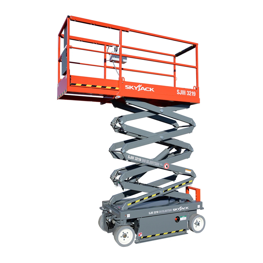
Skyjack SJ 3219 Operating Manual
Compact & conventional series (ce)
Hide thumbs
Also See for SJ 3219:
- Service manual (114 pages) ,
- Operation manual (114 pages) ,
- Service manual (155 pages)

Related Manuals for Skyjack SJ 3219


Summary of Contents for Skyjack SJ 3219
- Page 1 MODELS SJ 3215 SJ 3219 SJ 3220 SJ 3226 SJ 4620 SJ 4626 SJ 4632 Operating Manual Compact & Conventional Series (CE) 155150AB-A September 2010...
-
Page 2: Serial Number Of Machine
Note If your machine’s serial number is not listed above, please refer to www.skyjack.com a complete list of older machine models/operating manuals. Skyjack Service Center 3451 Swenson Ave. St. Charles, Illinois, 60174 USA Phone: 630-262-0005 Toll Free: 1-800-275-9522 Fax: 630-262-0006 Email: service@skyjack.com... - Page 3 The Safety Alert Symbol identifies important safety messages on aerial platform, safety signs This Safety Alert Symbol means attention! in manuals or elsewhere. When you see this symbol, be alert to the possibility of personal Become alert! Your safety is involved. injury or death.
-
Page 4: Table Of Contents
Table of Contents Section 1 - About Your Aerial Platform Read and Heed Aerial Platform Definition .............................7 Purpose of Equipment ..............................7 Use of Equipment ................................7 Manual ..................................7 Operator ..................................7 Service Policy and Warranty ............................7 Optional Accessories ..............................7 Scope of this Manual ..............................7 Safety Rules Operator Safety Reminders ............................8 Electrocution Hazard ..............................8... - Page 5 Table of Contents Section 2 - Operation (Continued) Component Identification (Special Options) ....................22 2.6-1 Powered Extension Control Console (If Equipped) ................22 2.6-2 1500W AC Inverter (If Equipped) ......................22 2.6-3 Motion Alarm (If Equipped) .......................22 Operator’ Responsibility ..........................23 Visual and Daily Maintenance Inspections .....................24 Function Tests..............................31 2.10 Start Operation ..............................38 2.10-1...
-
Page 6: Purpose Of Equipment
SKYJACK warrants each new SJIII Series work platform to be free of defective parts and workmanship for the first 24 months. Any defective part will be replaced or repaired by your local SKYJACK dealer at no charge for parts or labor. -
Page 7: Safety Rules
Common sense dictates the use of protective clothing when working on or near machinery. Use appropriate safety devices to protect your eyes, ears, hands, feet and body. Any modifications from the original design are strictly forbidden without written permission from SKYJACK. Electrocution Hazard This aerial platform is not electrically insulated. -
Page 8: Safety Precautions
Section 1 - About Your Aerial Platform Safety Rules Safety Precautions Know and understand the safety precautions before going on to next section. wARNiNG Failure to heed the following safety • Do Not increase the lateral precautions could result in tip over, surface area of the platform. - Page 9 Safety Rules Section 1 - About Your Aerial Platform Safety Precautions (Continued) Know and understand the safety precautions before going on to next section. • Do Not operate on surfaces not capable of • Do Not raise the aerial platform holding the weight of the aerial platform including while the aerial platform is on a the rated load, e.g.
- Page 10 • has been tagged or locked out for non-use or or materials that exceed the confines of the repair. guardrails unless approved by Skyjack. Failure to avoid these hazards could wARNiNG result in death or serious injury. Entering and exiting the aerial platform...
-
Page 11: Section 2 - Operation
Section 2 - Operation General 2.0 Operation • The operator must be sure that the aerial platform This section provides the necessary information needed has been properly maintained and inspected to operate the aerial platform. It is important that the user before using it. -
Page 12: Major Components
Section 2 - Operation 2.2 Major Components Platform Control Manual Storage Console Extension Main Platform Platform Lifting Mechanism Maintenance Support Hydraulic/Electric Tray Battery Tray Base Pothole Protection Device SKYJACK SJIII Series Aerial Platform SJIII Compacts & Conventionals Page 14 December 2007... -
Page 13: Major Assemblies
Section 2 - Operation Major Assemblies 2.3 Major Assemblies 2.4 Serial Number Nameplate The aerial platform consists of three major assemblies: The serial number nameplate, located at the rear of the base, lifting mechanism and platform. aerial platform, lists the following: 2.3-1 Base •... -
Page 14: Component Identification
Component Identification Section 2 - Operation 2.5 Component Identification 2.5-3 Load Sensing System This system is a safety device that will prevent any The following descriptions are for identification, normal movement of the aerial platform from a stationary explanation and locating purposes only. working position after the rated load is reached and 2.5-1 Main Power Disconnect Switch exceeded. -
Page 15: Base Control Console
Section 2 - Operation Component Identification 2.5-4 Base Control Console 2.5-5 Electrical Panel This control console is located at the rear of the base. This panel is located in the hydraulic/electric tray. It It contains the following controls: contains the following controls: Figure 2-3. -
Page 16: Free-Wheeling Valve
Component Identification Section 2 - Operation 2.5-7 Free-wheeling Valve 2.5-9 Pothole Protection Device Models 3220, 3226, and 46xx Figure 2-7. Pothole Protection Device Pothole Protection Device - This device consists of a set of mechanically actuated steel weldments located under the hydraulic/electric tray and battery tray. -
Page 17: 10 Emergency Lowering System
Section 2 - Operation Component Identification 2.5-10 Emergency Lowering System 2.5-12 Maintenance Support This emergency lowering system allows platform lowering in the event of an emergency or an electrical system failure. Refer to Section 2.15 for the emergency lowering procedure. The system contains the following controls: Figure 2-9. -
Page 18: 13 Platform Control Console
Component Identification Section 2 - Operation 2.5-13 Platform Control Console Emergency Stop Button/Operation Light - This This removable control console is mounted at the right button “ ”, when depressed, disconnects front of the platform. It contains the following controls: power to the control circuit. -
Page 19: 14 Manual Storage Box
Section 2 - Operation Component Identification 2.5-14 Manual Storage Box 2.5-16 Lanyard Attachment Anchorage This weather-resistant box is mounted on the platform railings. It contains the operating manual, EC declaration and other important documents. The operating manual for this make and model of aerial platform must be stored in this box. -
Page 20: Component Identification (Special Options)
Component Identification (Special Options) Section 2 - Operation 2.6 Component Identification 2.6-2 1500W AC Inverter (If Equipped) The inverter is located on the base of the aerial platform. (Special Options) It has the following controls: This section describes the components that are optional to aerial platforms. -
Page 21: Operator' Responsibility
Section 2 - Operation Operator’s Responsibility 2.7 Operator’s Responsibility Repairs to the aerial platform may only be made by a qualified service technician. After repairs are completed, It is the responsibility of the operator, prior to each work the operator must perform visual and daily maintenance shift, to perform the following: inspections &... -
Page 22: Visual And Daily Maintenance Inspections
Visual and Daily Maintenance Inspections Section 2 - Operations High Speed Limit Switch High Speed Limit Switch Pothole Protection Limit Switch COMPACTS CONVENTIONALS 2.8 Visual & Daily Maintenance 2.8-1 Labels Refer to the labels section in this manual and determine Inspections that all labels are in place and are legible. - Page 23 Section 2 - Operation Visual and Daily Maintenance Inspections Compact Conventional Free-wheeling (Back View) 220V Outlet Valve Receptacle CAUTION 106515AC Main Power Base Control Disconnect Console Ladder Switch Free-wheeling Valve Compact (Back View) 2.8-5 Entrance Side • 220V Outlet Receptacle Ensure receptacle is free from dirt and •...
- Page 24 Visual and Daily Maintenance Inspections Section 2 - Operations Conventional Compact Battery Battery Charger Battery Charger Hydraulic/Electric Battery Fuse Box Battery Tray Battery Tray Pothole Protection Device Tray 2.8-6 Battery Tray Side wARNiNG • Pothole Protection Device Battery acid is extremely corrosive - Wear proper eye and facial protection as Ensure mechanisms have no sign of well as appropriate protective clothing.
- Page 25 Section 2 - Operation Visual and Daily Maintenance Inspections Conventional Steer Cylinder Wheel/Tire Battery Tray Tie Rod • Steer Cylinder Assembly • Tie Rod (Conventionals) Ensure steer cylinder assembly is Ensure there are no loose or missing properly secured and there are no loose parts, tie rod end studs are locked and or missing parts.
- Page 26 Visual and Daily Maintenance Inspections Section 2 - Operations Compact Emergency Lowering Greasing Point Access Rod Electrical Panel Load/Tilt Sensor Hydraulic/Electric Tray Main Manifold Greasing Point Hydraulic Pump and Motor Hydraulic Tank 2.8-7 Hydraulic/Electric Tray Side • Proportional and Main Manifolds Ensure tray latch is secure and in proper Ensure all fittings and hoses are properly working order.
- Page 27 Section 2 - Operation Visual and Daily Maintenance Inspections Platform Control Console Platform Railing Manual Storage Platform Assembly 2.8-8 Platform Assembly • Platform Control Console Ensure all switches and controller are returned to neutral and are properly wARNiNG secured. Ensure that you maintain three points of Ensure there are no loose or missing contact to mount/dismount platform.
- Page 28 Visual and Daily Maintenance Inspections Section 2 - Operations Powered Extension Control Console Maintenance Support Lift Cylinder Scissor Bumper Scissor Assembly Roller • Powered Extension Control Console Ensure cables and wires are properly (If Equipped) routed and shows no signs of wear and/ Ensure all switches are returned to or physical damage.
-
Page 29: Function Tests
Section 2 - Operation Function Tests Conventional Compact (Back View) (Back View) Free-wheeling Valve Lower/ Lower/ Neutral/Raise Neutral/Raise Switch Switch CAUTION 106515AC Emergency Stop Emergency Stop Off/Platform/Base Switch Button Button 2.9 Function Tests 2.9-2 Base Control Console Function tests are designed to discover any malfunctions before aerial platform is put into service. - Page 30 Function Tests Section 2 - Operation Conventional Compact (Back View) (Back View) Free-wheeling Valve Lower/ Lower/ Neutral/Raise Neutral/Raise Switch Switch CAUTION 106515AC Emergency Stop Emergency Stop Off/Platform/Base Switch Button Button • Test Base Emergency Stop 2. Select off/platform/base key switch to “ ”...
- Page 31 Section 2 - Operation Function Tests Conventional Compact (Back View) (Back View) Free-wheeling Valve Lower/ Lower/ Neutral/Raise Neutral/Raise Switch Switch CAUTION 106515AC Emergency Stop Emergency Stop Off/Platform/Base Switch Button Button • Test Emergency Lowering • Test Free-wheeling 1. Raise the platform. 1.
- Page 32 Function Tests Section 2 - Operation Lift/Drive/Steer Enable Lift/Drive/Steer Enable Trigger Switch Trigger Switch Rocker Switch Rocker Switch Emergency Stop Button/ Controller Operation Light Emergency Stop Button/ Inclined Drive/Level Drive Operation Light Switch Horn Pushbutton Horn Pushbutton Lift/Off/Drive Switch Lift/Inclined Drive/Level Drive Switch Platform Control Console with Toggle Switch Platform Control Console with Rotary Switch 2.9-3 Platform Control Console...
- Page 33 Section 2 - Operation Function Tests Lift/Drive/Steer Enable Lift/Drive/Steer Enable Trigger Switch Trigger Switch Rocker Switch Rocker Switch Emergency Stop Button/ Controller Operation Light Emergency Stop Button/ Inclined Drive/Level Drive Operation Light Switch Horn Pushbutton Horn Pushbutton Lift/Off/Drive Switch Lift/Inclined Drive/Level Drive Switch Platform Control Console with Toggle Switch Platform Control Console with Rotary Switch 3.
- Page 34 Function Tests Section 2 - Operation Lift/Drive/Steer Enable Lift/Drive/Steer Enable Trigger Switch Trigger Switch Rocker Switch Rocker Switch Emergency Stop Button/ Controller Operation Light Emergency Stop Button/ Inclined Drive/Level Drive Operation Light Switch Horn Pushbutton Horn Pushbutton Lift/Off/Drive Switch Lift/Inclined Drive/Level Drive Switch Platform Control Console with Toggle Switch Platform Control Console with Rotary Switch •...
- Page 35 Section 2 - Operation Function Tests Compact Pothole Protection Device • Test Pothole Sensor • Test Elevated Drive Speed wARNiNG wARNiNG Ensure that you maintain three points of Be aware of overhead obstructions contact to mount/dismount platform. or other possible hazards around the aerial platform when lifting.
-
Page 36: Start Operation
Start Operation Section 2 - Operation 2.10 Start Operation 2.10-1 To Activate Base Control Console Carefully read and completely understand the operating manual and all warnings and instruction labels (refer to wARNiNG labels section) on the aerial platform. Ensure that you maintain three points of contact when using the ladder to mount/ wARNiNG dismount platform. -
Page 37: To Activate Platform Control Console
Section 2 - Operation Start Operation Lowering Warning System - A lowering warning For platform control console with toggle switch: system automatically stops lowering function Select lift/off/drive switch to “ ” lift position. before reaching fully retracted position and sounds the alarm. After the operator has released For platform control console with rotary switch: down controls and taken time to check that no Select lift/inclined drive/level drive switch to “... -
Page 38: To Drive Forward Or Backward
Start Operation Section 2 - Operation 2.10-5 To Drive Forward or Backward 2.10-6 To Steer Activate platform control console (refer to wARNiNG Section 2.10-3). Be aware of blind spots when operating the aerial platform. For platform control console with toggle switch: Select lift/off/drive switch to “... -
Page 39: To Select Level Drive Or Inclined Drive Mode
Section 2 - Operation Start Operation 2.10-7 To Select Level Drive or Inclined Drive 2.10-8 To Extend/Retract Manual Extension Mode (If Equipped) Platform Level Drive Mode DANGER Select level drive mode when traveling on flat Crushing Hazard - Extension platform surface. -
Page 40: To Extend/Retract Powered Extension Platform (If Equipped)
Start Operation Section 2 - Operation 2.10-9 To Extend/Retract Powered Extension 2.10-10 Electrical Inverter (If Equipped) Platform (If Equipped) Turn main power disconnect switch to “ ” on To extend/retract powered extension platform, position. ensure “ ” emergency stop button is pulled out. -
Page 41: Guardrail Folding Procedure
Section 2 - Operation Guardrail Folding Procedure 2.11 Guardrail Folding Procedure Remove the platform control console and outrigger When folder down, the folding guardrail system reduces control console (if equipped) and lay it down on the height of the retracted aerial platform for transporting the platform. -
Page 42: Loading/Unloading
Loading/Unloading Section 2 - Operation 2.12 Loading/Unloading 2.12-1 Lifting Know and heed all national, state or territorial/provincial and local rules which apply to your loading/unloading wARNiNG of aerial platforms. Only qualified rigger shall operate machinery during lifting. Only qualified personnel shall operate machinery during loading/unloading. -
Page 43: Driving
The aerial platform can be lifted with a • Aerial platform speed should be on high torque forklift from the sides but Skyjack does setting (if equipped). not recommend this use. Lift with forks in designated pockets as illustrated in... -
Page 44: Moving The Aerial Platform Through A Doorway
Moving the Aerial Platform Through a Doorway Section 2 - Operation 2.13 Moving the Aerial Platform Through Note For some models, the connection is located a Doorway beneath an access panel which requires that the scissor assembly be raised to access it. wARNiNG This procedure is suitable for level Ensure there are no personnel in the intended... - Page 45 Section 2 - Operation Moving the Aerial Platform Through a Doorway O n c e s a f e l y t h r o u g h d o o r w a y, p u s h i n “...
-
Page 46: Winching And Towing Procedures
Winching and Towing Procedures Section 2 - Operation 2.14 Winching and Towing Procedures 2.14-1 To Release Free-wheeling Valve This section provides the operator with procedures Ensure aerial platform is on level ground. Chock about towing and winching and on how to manually or block the wheels to keep aerial platform from release the brakes. -
Page 47: To Release Brakes Manually
Section 2 - Operation Winching and Towing Procedures 2.14-2 To Release Brakes Manually Remove wheel chocks or blocks, then push, winch or tow aerial platform to desired location. wARNiNG wARNiNG Do not manually disengage brakes if the aerial platform is on a slope. Brakes must be reengaged immediately after reaching the desired location. -
Page 48: Emergency Lowering Procedure
Emergency Lowering Procedure Section 2 - Operation 2.15 Emergency Lowering Procedure This section guides the operator on how to use the emergency lowering system. This system allows platform lowering in the event of an emergency or an electrical system failure. wARNiNG Keep clear of scissors mechanism when using emergency lowering valve. -
Page 49: Maintenance Support Procedure
Section 2 - Operation Maintenance Support Procedure 2.16 Maintenance Support Procedure To Store the Maintenance Support This section provides the operator with procedure regarding deployment and storage of maintenance Turn main power disconnect switch to “ ” on support. position. The maintenance support is a safety mechanism Raise platform until there is adequate clearance designed to support the scissor assembly. -
Page 50: Battery Maintenance
Battery Maintenance Section 2 - Operation 2.17 Battery Maintenance 2.17-2 Battery Charging Operation This section provides the operator with procedures on how to service and charge the battery. This also provides charger operation instructions. 2.17-1 Battery Service Procedures wARNiNG Explosion Hazard - Keep flames and Figure 2-25. -
Page 51: Charging State Led
Section 2 - Operation Battery Maintenance Charging State LED CAUtioN When changing the input voltage wait State of charge until all the LEDs are OFF or wait a 0 to 50% Blinking 50% to 75% Blinking minimum of 20 seconds before switching 75% to 100% Blinking on the new voltage. - Page 52 Battery Maintenance Section 2 - Operation Batteries do not fully charge. If the batteries are charged overnight, make sure the AC supply is not being switched off at night with other building items. Check battery condition and for dead cells or reduced capacity. Replace charger only if other problems are not found.
-
Page 53: Table 2.1 Standard And Optional Features
Tables Section 2 - Operation Table 2.1 Standard and Optional Features - CE Compacts Conventionals Models 3215 3219 3220 3226 4620 4626 4632 S T A N D A R D E Q U I P M E N T Base control console Color coded and numbered wiring system DC power (VDC) -
Page 54: Table 2.2 Owner's Annual Inspection Record
Table 2.2 Owner’s Annual Inspection Record Model Number: ________________________ Serial Number: _________________________ Inspection Date Recording Year Owner’s Skyjack Name Inc. Inspected Skyjack Inc. 158AA As described earlier in this section, this decal is located on the scissor assembly. It must be completed after an annual inspection has been completed. -
Page 55: Tables
Tables Section 2 - Operation Table 2.3a Specifications and Features MODEL 3215 3219 3220 3226 1120 kg 1312 kg 1599 kg 1891 kg Weight 0.81 m 0.83 m Overall width 1.80 m 2.34 m Overall length 0.66 m x 1.63 m 0.70 m x 2.10 m Platform Size (inside) Height... - Page 56 Section 2 - Operation Tables Table 2.3b Specifications and Features MODEL 4620 4626 4632 1980 kg 2170 kg 2300 kg Weight 1.2 m Overall width 2.3 m Overall length 1.1 m x 2.1 m Platform Size (inside) Height Working Height 8.1 m 9.9 m 11.8 m...
-
Page 57: Table 2.4 Floor Loading Pressure
Tables Section 2 - Operation Table 2.4 Floor Loading Pressure Total Aerial Total Aerial Platform Load Platform MODEL Wheel LCP** OUP** Weight kPa (kN/m kPa (kN/m min* 1120 685.9 3215 max* 1347 742.4 min* 1312 743.4 3219 max* 1539 782.0 10.6 min* 1542... - Page 58 Intermixing tires of different types or using tires of types other than those originally supplied with this equipment can adversely affect stability. Therefore, replace tires only with the exact original Skyjack-approved type. Failure to operate with matched approved tires in good condition may result in death or serious injury.
-
Page 59: Table 2.5 Maximum Platform Capacities (Evenly Distributed)
Tables Section 2 - Operation Table 2.5 Maximum Platform Capacities (Evenly Distributed) Maximum Tilt Manual Extension Platform Powered Extension Platform MODEL Wind Cutout Total Capacity Extension Capacity Total Capacity Extension Capacity Speed Setting 227 kg 2 Persons 113 kg 1 Person No Wind 3215 1.5 x 3.5... - Page 60 Section 2 - Operation Tables Table 2.6 EC Declaration of Conformity EC Declaration of Conformity We, SKYJACK Inc., [*], declare under our sole responsibility that the product Scissor Type Elevating Work Platform Model number: [*] Serial number: [*] To which this declaration relates is in conformity with the following directives:...
-
Page 61: Table 2.7 Maintenance And Inspection Schedule
B - Perform Scheduled Maintenance Inspection. Refer to Service & Maintenance manual. * - Maintenance must be performed only by trained and competent personnel who are familiar with mechanical procedures. † - Refer to Skyjack's website @ www.skyjack.com for latest service bulletins prior to performing quarterly or yearly inspection. -
Page 62: Table 2.8 Operator's Checklist
Hourmeter Reading: Operator's Name (Printed): Date: Time: Operator's Signature: Each item shall be inspected using the the appropriate section of the Skyjack operating manual. As each item is inspected, check the appropriate box. INSPECTION FREQUENCY - PASS FREQUENTLY - FAIL... -
Page 63: Labels
CE rating mark Caution Tape Stripe Caution stripe Wheel Load. Indicates rated wheel load. Tape - Red/Blue/Red Skyjack pinstripe “Keep” Keep clear. Skyjack Logo Small Skyjack logo - blue and red “Clear” Keep clear. SJIII Compacts & Conventionals Page 66 December 2007... - Page 64 Place spacers only as shown in diagram. *Spacers vary over different units. Crushing Hazard Danger - Crushing hazard Tape Blue/White Skyjack pinstripe Model Number* Product Identifier *Model number will vary, may not be as shown. Battery - Charger Connection Connect charger to batteries at this point.
- Page 65 Labels Section 2 - Operation Labels and Nameplates - Models 3215 & 3219 Front Side Lift Cylinder Label Pictorial Description Crushing Hazard Danger - Crushing hazard Caution Tape Stripe Caution stripe Maintenance Support Deploy maintenance support here. Free-wheeling Valve Open valve to initiate free wheeling prior to winching/towing/pushing.
- Page 66 Caution Tape Stripe Caution stripe Wheel Load. Indicates rated wheel load. Tape - Red/Blue/Red Skyjack pinstripe Crushing Hazard Danger - Crushing hazard “Keep” Keep clear. Skyjack Logo Small Skyjack logo - blue and red SJIII Compacts & Conventionals December 2007 Page 69...
- Page 67 Use or operation of an uninspected aerial platform could result in death or serious injury! Tape Blue/White Skyjack pinstripe Lanyard Anchorage Point Attach anchorage harness lanyard here. Skyjack Logo Small Skyjack logo - blue “Keep Clear” Keep clear. SJIII Compacts & Conventionals Page 70 December 2007...
- Page 68 Section 2 - Operation Labels Labels and Nameplates - Models 3215 & 3219 Left Side (Continued) Electrical Panel Hydraulic Tray Label Pictorial Description Ground Circuit Breaker Push to reset ground circuit breaker. Power Circuit Breaker Push to reset power circuit breaker. Hydraulic Oil ATF Dexron III Replace hydraulic fluid with ATF Dexron III only.
- Page 69 Labels Section 2 - Operation Labels and Nameplates - Models 3215 & 3219 Back Side Label Pictorial Description Base Control Console Select “ ” to lower or “ ” raise platform. Select “ ” platform to enable platform controls, “ ”...
- Page 70 Section 2 - Operation Labels Labels and Nameplates - Models 3215 & 3219 Back Side (Continued) Label Pictorial Description Winching/Towing/Pushing Procedure Winching/towing/pushing procedure. Ensure brake is released and free-wheeling valve is open before moving the unit manually. Main Power Disconnect Rotate clockwise to turn on main power;...
- Page 71 Labels Section 2 - Operation Labels and Nameplates - Models 3215 & 3219 Back Side (Continued) Label Pictorial Description Inverter Switch Turn inverter switch to off position after use. Warning - Do Not Alter Aerial platform altering warning Operator Checklist Operator checklist.
- Page 72 Section 2 - Operation Labels Labels and Nameplates - Models 3215 & 3219 Top Side Outlet Box Railing Pins Label Pictorial Description Forklift Pocket Insert fork fully into pocket to lift aerial platform. Lift and Tie Down Points Only use these points for lifting or tying down. Warning - Do Not Alter Aerial platform altering warning Maintenance Support...
- Page 73 Labels Section 2 - Operation Labels and Nameplates - Models 3215 & 3219 Platform Control Console with Toggle Switch Label Pictorial Description Platform Control Console Squeeze “ ” trigger to enable controller. Operate “ ” rocker switch to steer. Move controller handle forward to “ ”...
- Page 74 Section 2 - Operation Labels Labels and Nameplates - Models 3215 & 3219 Platform Control Console with Rotary Switch Label Pictorial Description Platform Control Console Squeeze “ ” trigger to enable controller. Operate “ ” rocker switch to steer. Move controller handle forward to “ ”...
- Page 75 Labels and Nameplates - Models 3220, 3226 & 46xx Right Side Label Pictorial Description “Keep” Keep clear. Skyjack Logo Small Skyjack logo - blue Tape Blue/White Skyjack pinstripe Tape - Red/Blue/Red Skyjack pinstripe Wheel Load.* Indicates rated wheel load. *Wheel load will vary with each model.
- Page 76 Labels Labels and Nameplates - Models 3220, 3226 & 46xx Right Side (Continued) Battery Tray Label Pictorial Description Skyjack Logo Small Skyjack logo - blue and red Caution Tape Stripe Caution stripe “CE” CE rating mark Model Number* Product Identifier *Model number will vary, may not be as shown.
- Page 77 Labels Section 2 - Operation Labels and Nameplates - Models 3220, 3226 & 46xx Front Side Label Pictorial Description Crushing Hazard Danger - Crushing hazard Maintenance Support Deploy maintenance support here. Lift and Tie Down Points Only use these points for lifting or tying down. Caution Tape Stripe Caution stripe SJIII Compacts &...
- Page 78 Section 2 - Operation Labels Labels and Nameplates - Models 3220, 3226 & 46xx Left Side Label Pictorial Description Skyjack Logo Small Skyjack logo - blue “CE” CE rating mark Caution Tape Stripe Caution stripe Wheel Load.* Indicates rated wheel load.
- Page 79 Hydraulic Oil ATF Dexron III Replace hydraulic fluid with ATF Dexron III only. Skyjack Logo Small Skyjack logo - blue and red Annual Inspection WARNING Do not u se or ope rate this aerial pla tform if a n inspec tion has not Ensure that work platform has received annual inspection prior been per formed w ithin 6 m onths of last reco rded insp ection da te.
- Page 80 Labels Labels and Nameplates - Models 3220, 3226 & 46xx Left Side (Continued) Electrical Panel Label Pictorial Description Tape Blue/White Skyjack pinstripe Model Number* Product Identifier *Model number will vary, may not be as shown. “Clear” Keep clear. “Keep” Keep clear.
- Page 81 Labels Section 2 - Operation Labels and Nameplates - Models 3220, 3226 & 46xx Back Side Avoid Avoid power Avoid slopes overhead lines obstructions Avoid Ladders, Avoid lightning scaffolding prohibited crushing and storms hazards Avoid Be aware Avoid side of blind wind forces spots...
- Page 82 Section 2 - Operation Labels Labels and Nameplates - Models 3220, 3226 & 46xx Back Side (Continued) Avoid Avoid power Avoid slopes overhead lines obstructions Avoid Ladders, Avoid lightning scaffolding prohibited crushing and storms hazards Avoid Be aware Avoid side of blind wind forces...
- Page 83 Labels Section 2 - Operation Labels and Nameplates - Models 3220, 3226 & 46xx CAUTION 106515AC Back (46xx) Label Pictorial Description Base Control Console Select “ ” to lower or “ ” raise platform. Select “ ” platform to enable platform controls, “ ”...
- Page 84 Section 2 - Operation Labels Labels and Nameplates - Models 3220, 3226 & 46xx CAUTION 106515AC Back (46xx) Label Pictorial Description Free-wheeling Valve Open valve to initiate free wheeling prior to winching/towing/pushing. Winching/Towing/Pushing Procedure Winching/towing/pushing procedure. Ensure brake is released CAUTION and free-wheeling valve is open before moving the unit Instructions for towing, pushing or...
- Page 85 Labels Section 2 - Operation Labels and Nameplates - Models 3220, 3226 & 46xx Top View Railing Pins Platform Label Pictorial Description Lift and Tie Down Points Only use these points for lifting or tying down. Forklift Pocket Insert fork fully into pocket to lift aerial platform. Maintenance Support Instructions on use on maintenance support Lanyard Anchorage Point...
- Page 86 Section 2 - Operation Labels Labels and Nameplates - Models 3220, 3226 & 46xx Platform Control Console with Toggle Switch Label Pictorial Description Platform Control Console Squeeze “ ” trigger to enable controller. Operate “ ” rocker switch to steer. Move controller handle forward to “...
- Page 87 Labels Section 2 - Operation Labels and Nameplates - Models 3220, 3226 & 46xx Platform Control Console with Rotary Switch Label Pictorial Description Platform Control Console Squeeze “ ” trigger to enable controller. Operate “ ” rocker switch to steer. Move controller handle forward to “...
- Page 88 Section 2 - Operation Labels Labels and Nameplates - Models 3220, 3226 & 46xx Control Box - Powered Cross Member- 1st Level Extension Platform Inside Scissors Label Pictorial Description Lift Enable Select to enable lift mode. Powered Extension Platform Extend/Retract Select “...
- Page 89 Reliable lift solutions by people who care. www.skyjack.com...
Need help?
Do you have a question about the SJ 3219 and is the answer not in the manual?
Questions and answers