Table of Contents
Advertisement
Quick Links
Advertisement
Table of Contents

Subscribe to Our Youtube Channel
Related Manuals for Malaguti MALBO Line


Summary of Contents for Malaguti MALBO Line
-
Page 2: Table Of Contents
CONTENTS DESCRIPTION PAGE INTRODUCTION NOTES FOR EASY CONSULTATION SPECIFICATIONS MAIN COMPONENTS IDENTIFICATION DATA: CHASSIS N° / ENGINE N° ANTI-TAMPERING PLATE TIRES PRESSURE FUEL TANK FRONT LUGGAGE COMPARTMENT REAR-VIEW MIRROR HELMET COMPARTMENT LUGGAGE HOOK INSTRUMENT BOARD HANDLEBAR CONTROLS RIGHT HAND CONTROL (FIG. 17) LEFT HAND CONTROL (FIG. - Page 3 DESCRIPTION PAGE DISMANTLING THE BRAKE PAD SET FRONT FORK DISMANTLING THE FORK REPLACING CAPS AND STEERING CONES DISMANTLING THE FORK OIL LEVEL CHECK MAIN IGNITION SWITCH REAR WHEEL AND SHOCK ABSORBER DISMANTLING THE REAR WHEEL DISMANTLING THE BRAKE SHOES DISMANTLING THE SHOCK ABSORBER CHECKING THE BRAKE HUB CHECKING BRAKE SHOES CHECKING THE SHOCK ABSORBER...
- Page 4 DESCRIPTION PAGE REPLACING CENTRIFUGAL ROLLERS DISMANTLING THE CLUTCH ASSY ASSEMBLING THE CLUTCH ASSY DISMANTLING THE CARBURETTOR DISMANTLING THE STARTER DISMANTLING THE VALVE DISMANTLING THE FLOAT, NEEDLE AND JET REMOVE THE IDLE SCREW AND IDLING ADJUSTING SCREW CYCLE TIGHTENING TORQUES ENGINE TIGHTENING TORQUE TIGHTENING TORQUE (GENERIC TABLE) FRAME DIMENSION CHECKS ELECTRICAL PART LOCATION...
-
Page 5: Introduction
INTRODUCTION NOTES FOR EASY CONSULTATION - MALBO Line makes on-going efforts to perfect all its For a quick and easy interpretation, symbols have been vehicles as well as the manuals supplied with them. used to highlight situations requiring extra attention, practical advice or just information. -
Page 6: Specifications
SPECIFICATIONS Ignition Electronic. MALBO Line reserves the right to modify the specifica- tions at any time without prior notice. Brakes Front brake: disk type, Ø 155 mm transmission and hydraulic calipers. Rear brake: drum Ø 110 mm mechanical transmission. Chassis High resistance tubular steel frame. -
Page 7: Main Components
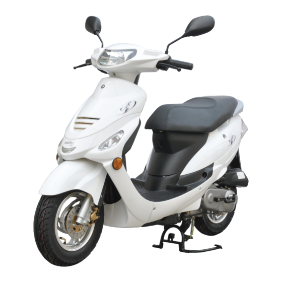
MAIN COMPONENTS 1 - Headlight 2 - Front turn indicator 3 - Passenger footboard 4 - Centre stand 5 - Battery - Protection fuses 6 - Helmet compartment 7 - Tail lamp 8 - Number plate holder 9 - Muffler 10 - Luggage hooks 11 - Front luggage compartment Fig. -
Page 8: Tires
TIRES PRESSURE Type: Tubeless (without inner tube) The pressure of tires must be adjusted while the tire is at ambient temperature. Pressure differing from that indicated can lead to higher fuel consumption, irregular wear of 3.50-10 42J 3.50-10 42J Fig. 07 the tire, impaired vehicle performance and rid- ing conditions. -
Page 9: Fuel Tank
FUEL TANK FRONT LUGGAGE COMPARTMENT To gain access to the fuel tank, proceed as follows: This is located at the centre of the lower fairing (A- Fig. 11). It can be used for storage small and light ob- - Place the vehicle on the centre stand. jects. -
Page 10: Helmet Compartment
HELMET COMPARTMENT INSTRUMENT BOARD - This is located under the seat. The helmet compart- 1 - Analogue instruments, Speedometer This indicates the current speed in kmh or mph. ment can contain a Jet helmet. Some types of helmet 2 - Odometer may not fit into the compartment. -
Page 11: Handlebar Controls
HANDLEBAR CONTROLS LEFT HAND CONTROL (FIG. 18) 1) Rear brake lever RIGHT HAND CONTROL (FIG. 17) Horn button. 1) Throttle grip 2) Front brake lever Turn indicator switch. 3) Engine stop: 4) Button for turning off indicator lights right = Position - Engine stop 5) Light switch: left = Position - Engine starting high beam... -
Page 12: Maintenance Table
Due to their simplicity, checks featuring an asterisk CAN also be carried out by technicians not author- ised by MALBO Line or MALAGUTI, but under their direct responsibility. TRANSMISSION OIL Checking level/topping up every 5,000 km/3,120... -
Page 13: Engine Oil
ENGINE OIL Topping up Before topping up, check the oil level and in no case Check oil level EVERY 500 KM (310 MILES) allow the level to rise above the MAX notch. As far as four-stroke engines are concerned, engine oil is Never allow the level to rise above the MAX used to lubricate distribution components, base bearings mark! Excessive internal pressure can impair... -
Page 14: Lubricant Table
LUBRICANT TABLE NOTE - The vehicle’s life depends also on the care devoted to lubricating it. SPARK PLUG Replace every 5,000 km (3,120 mi) finger tight. Then, using the special spark plug The spark plug is an essential component: wrench, wrench it to the recommended torque wrench setting: 17.5 Nm / 1.75 kgm. -
Page 15: Checking The Pads And Disc Of The Front Brake (Condition And Wear)
CHECKING THE PADS AND DISC OF THE FRONT BRAKE (CONDITION AND WEAR) 1 - We recommend you to check the front pads and disc every 2,500 km (1,560 mi). 2 - The minimum thickness of the brake lining shall not be less than 2 mm (Fig. -
Page 16: Tail Lamp (With Stop Light)
TAIL LAMP (WITH STOP LIGHT) - Parking/Stop light (B-Fig. 30) Bulb 12V - 21W/5W - Rear turn indicator (E-Fig. 30) Bulb 12V - 10W (R10W) NOTE - Visually check if the stop light works properly, by pulling one of the two brake levers. Fig. -
Page 17: Battery (12V - 5Ar)
Battery (12V - 5Ar) The battery compartment is located in the front section of the vehicle. Fitting battery (operation performed before delivery) To fit battery, proceed as follows: - Take a previously charged battery. - Remove the rubber mat. - Loosen the four screws (V-Fig. 32) and remove the bat- tery cover (C-Fig. -
Page 18: Fairing
FAIRING Fig. 01 Item Item Handlebar cover (front) Rear fairing r/h Handlebar cover (rear) Rear fairing l/h Front shield Central fairing Shield (lower) Side cover r/h Inner shield (upper) Side cover l/h Inner shield (lower) Central fairing VIN number cover Helmet compartment Foot board panel Seat... -
Page 19: Dismantling The Front Handlebar Cover
DISMANTLING THE FRONT HANDLEBAR COVER - Remove the RIGHT and LEFT mirrors (1) Fig. 02 - Remove the front handlebar cover (2). Fig. 03 - Disconnect the connector (3). Fig. 04 REPLACING THE HEAD LIGHT BULB - Disconnect the connector (1) and replace the light bulb (2). -
Page 20: Dismantling The Rear Handlebar Cover
DISMANTLING THE REAR HANDLEBAR COVER - Remove the rear handlebar cover (1). - Remove the speedometer cable (2). Fig. 06 DISMANTLING THE FRONT SHIELD - Remove the front shield (3). Fig. 07 03/10... -
Page 21: Dismantling The Side Covers
DISMANTLING THE SIDE COVERS - Remove the central fairing (1). Fig. 08 - Remove the right and left side covers (2). Fig. 09 DISMANTLING THE TAIL LIGHT ASSY - Unscrew the tail glass screws. Fig. 10 03/10... -
Page 22: Dismantling The Rear Handle
- Release the tail cover glass by slighting pushing your thumbs on the illustrated points. NOTE - Be careful not to push too hard on the point (1); the glass could break. Fig. 11 - Tail light bulb (2). - Turn indicator light bulbs (3). Fig. -
Page 23: Dismantling The Helmet Compartment
- Remove the rear handle (2). Fig. 14 DISMANTLING THE HELMET COMPARTMENT - Open the seat. - Unscrew the illustrated screws and nuts. - Remove the helmet compartment (1). Fig. 15 DISMANTLING THE FAIRING - Remove the mat set (1). Fig. -
Page 24: Battery Box
- Unscrew the fuel tank cap (3). - Before removing the fairing, release the seat opening cable (4). Fig. 18 - Remove the fairing (5). Fig. 19 BATTERY BOX - Remove the battery cover (1). Fig. 20 - Remove the battery (2). - Remove the 10 Ampere fuse box holder (3). -
Page 25: Dismantling The Foot Board
DISMANTLING THE FOOT BOARD - Remove the battery (see specific chapter). - Remove the foot board (1). Fig. 22 DISMANTLING THE LOWER SHIELD AND INNER SHIELD - Remove the ignition barrel cover (1). - Remove the bag handle hook (2). Fig. -
Page 26: Replacing The Park Light And Turn Indicators Bulbs
REPLACING THE PARK LIGHT AND TURN INDICATORS BULBS - Pack light bulb (1). - Turn indicator light bulb (2). Fig. 25 DISMANTLING THE FRONT MUDGUARD - Release the two front mudguard halves (wheel side and shield side). - Remove the wheel as indicated in the specific chapter. Fig. - Page 27 - Remove the rear part (2) and front part (3). Fig. 28 03/10...
-
Page 28: Front Wheel
FRONT WHEEL Fig. 29 Item Item Front rim Brake disc Front tyre (Tubeless) Bolt M8x24 Spacer Spacer front brake Bearing 6002 (ø15x32x9) Nut M12 Bearing 6003 (ø17x35x10) Front wheel spindle Oil seal Speedo drive 03/10... -
Page 29: Dismantling The Front Wheel
DISMANTLING THE FRONT WHEEL Check perfect vehicle stability, positioned on the main stand. - Disconnect the speedometer cable (2). - Unscrew the nut (1). Cs - N * m Fig. 30 DISMANTLING THE FRONT BRAKE CALLIPER - Unscrew the front brake calliper screws (3). - Lift the vehicle using the lift and remove the wheel. -
Page 30: Front Rim Check (Wheel Removed)
FRONT RIM CHECK (WHEEL REMOVED) Check front rim oscillation (Radial and Axial) and make sure it does not exceed the service limit. If oscillation was caused by the bearing, the rim may be reused after replac- ing the bearing. Otherwise, replace with a new rim. Oscillation limit = 2.0 mm Fig. - Page 31 When reassembling: - Mount the springs (5) as indicated. - Mount the pad set (6) facing them in the indicated direc- tions (flat side (7) facing towards the cover). When reassembling the pad set, fully push the piston into its housing. After reassembling, pull the brake lever several times to position the pad set in contact with the brake disk.
-
Page 32: Front Fork
FRONT FORK Fig. 37 Item Item Handlebar Plug Bolt O-Ring Spring Bolt Piston tube Screw Seeger Lock nut Return spring Lock washer Fork tube Adjustable cone Dust seal Steering ball cages N° 26 (ø 5/32) Seeger Upper washer Oil seal Lower washer R/h fork leg assy Steering ball cages (lower) N°... -
Page 33: Dismantling The Fork
DISMANTLING THE FORK - Remove the handlebar cover. - Unscrew screw (1) and screw (2). - Remove the front wheel. - Remove the front mudguard. - Remove the calliper. - Remove the front shield - Slide the handlebar off the fork tube. Fig. -
Page 34: Dismantling The Fork
Install the following new parts: - Fork cone (7). - Steering caps (8). Fig. 41 DISMANTLING THE FORK - Lubricate the caps - Install 26 ball cages (9) for the upper cap and 29 ball cages (10) for the lower cap (ø 5/32). - Insert the fork in the steering shaft. -
Page 35: Main Ignition Switch
MAIN IGNITION SWITCH - Remove the front shield. - Unscrew the fixing screws. - Disconnect the connector. - Remove the key switch (1). Fig. 44 REAR WHEEL AND SHOCK ABSORBER Fig. 45 Item Item Rear rim Nut M6 Rear tire Washer Brake shoes Wheel nut... -
Page 36: Dismantling The Rear Wheel
DISMANTLING THE REAR WHEEL - Remove the exhaust. - Unscrew the nut (D). - Remove the rear wheel. Cs - N * m Fig. 46 DISMANTLING THE BRAKE SHOES - Remove the rear wheel. - Unscrew the screw (V). - Remove the brake shoes (1) being careful not to dam- age the springs (M). -
Page 37: Checking The Brake Hub
CHECKING THE BRAKE HUB Check the INTERNAL DIAMETER of the brake hub and re- place the rim if the INTERNAL DIAMETER exceeds wear limits. Wear limit: 120.7 mm Fig. 49 CHECKING BRAKE SHOES Make sure brake shoes are not worn or damaged and re- place the complete brake shoe set if necessary. -
Page 38: Dismantling The Main Stand
DISMANTLING THE MAIN STAND Secure the vehicle so that it does not fall when the main stand is removed. - Remove the split pin (1). Fig. 52 - Remove the spring (2). - Slide out the pin (3) and remove the main stand. Fig. - Page 39 - Remove the right and left side covers (2). Fig. 55 - Disconnect the carburettor starter connector (A) and stator connector (B). Fig. 56 - Release the throttle cable (3), the fuel hose (4) and de- pression hose (5). - Unscrew the filter box clamp (6). Fig.
- Page 40 - Disconnect the positive and negative starter motor ca- bles (7). Fig. 58 - Remove the rear brake cable adjustment nut (8). Fig. 59 - Remove the filter case (9). Fig. 60 - Unscrew the rear shock absorber screw (10). Fig.
- Page 41 - Slide off the spark plug cap (11). - Remove the main stand (see specific chapter). Fig. 62 - Unscrew the nut (12), slide off the engine pin and re- move the engine from the frame. Fig. 63 - Unscrew the screws (13). Cs - N * m Fig.
- Page 42 - Unscrew the nut (15) and remove the rear wheel. Fig. 66 03/10...
-
Page 43: Checking The End Compression Pressure
CHECKING THE END COMPRESSION PRESSURE - With the engine cold, remove the spark plug cap - Remove the spark plug. - Fit a compression testing pressure gauge in the spark plug seat with a spark plug fitting and tighten it. - Run the engine using the starter motor and with the carburettor fully open, until the reading on the pressure gauge is stable. -
Page 44: Engine Dismantling
ENGINE DISMANTLING - Place the engine on a suitable support. Fig. 01 - Unscrew the engine oil tank cap (1). - Unscrew the cap (2) and drain oil. Note: the filtering net (3) must be cleaned and the gasket replaced at each oil change. Cs - N * m Fig. -
Page 45: Dismantling The Assy Primary Pulley
DISMANTLING THE PRIMARY PULLEY ASSY - Unscrew the nut (1) and remove the washer (2). - Remove the kick starter plate (3). - Remove the fan (4). - Remove the primary fixed half pulley (5). Cs - N * m Fig. -
Page 46: Dismantling The Starter Motor
DISMANTLING THE STARTER MOTOR - Remove the 2 fixing screws (1). - Remove the starter motor (2) after disconnecting the positive wire. Cs - N * m Check starter motor O-Ring conditions. Fig. 07 DISMANTLING THE ETC INTAKE MANIFOLD - Unscrew the 2 intake manifold fixing nuts. - Remove the intake manifold. -
Page 47: Dismantling The Valve Cover
- Unscrew the 2 air conveyor fixing screws (4) on the clutch side. - Remove the air conveyors. - Remove the gasket (5). Fig. 10 DISMANTLING THE VALVE COVER - Unscrew the 4 fixing screws (1). - Unscrew the 2 secondary air hose screws (2). - Remove the valve cover with its gasket. -
Page 48: Dismantling The Rotor
DISMANTLING THE ROTOR - Unscrew the fan fixing screws (V - Remove the fan. Cs - N * m Fig. 13 - Lock the rotor with the specific tool. - Unscrew the nut (D). Cs - N * m Warning: using an unsuitable tool may deterio- rate the magneto flywheel coils. -
Page 49: Dismantling The Stator And Pick-Up
DISMANTLING THE STATOR AND PICK-UP - Unscrew the 2 pick-up fixing screws (1) and two stator fixing screws (2). - Remove the stator and pick-up. Cs - N * m Cs - N * m Fig. 16 DISMANTLING THE CHAIN TENSIONER - Unscrew the screw, O-Ring and chain tensioner spring (1). -
Page 50: Dismantling The Head
DISMANTLING THE HEAD - Remove the spark plug. - Manually rotate the engine shaft in the operating direc- tion to correctly align the rocker arm with the cam (A). Fig. 19 - Loosen the 2 screws (1). - Gradually loosen the four head nuts (2) in crossed order. - Remove the 4 nuts, washers and 2 screws. -
Page 51: Dismantling The Rocker Arms
DISMANTLING THE ROCKER ARMS - Remove the 2 rocker arm pins (1). - Remove the intake (2) and exhaust (3) rocker arms. Fig. 23 DISMANTLING VALVES AND VALVE STEM SEALS - Compress the valve spring using the specific tool. - Remove the 2 valve stem halves (1). - Decompress the spring and remove the tool. -
Page 52: Dismantling The Cylinder
When one valve is removed, always replace the relevant valve stem seals. - Using a specific tool, install a new valve stem seal. Fig. 26 - Reassemble valves, springs (7) and 2 valve stem halves (6) in the upper valve cup. When reassembled, thoroughly grease the rocker arm shafts, cams and contact points between the rocker arm and valve to avoid jamming when the... -
Page 53: Dismantling The Piston
DISMANTLING THE PISTON - Remove one of the seals (1). - Remove the piston pin. - Remove the piston (2). Fig. 30 DISMANTLING THE OIL SUMP - Unscrew the 4 screws (1) (85 mm). - Unscrew the 4 screws (2) (100mm). No tool is required to remove the oil sump. -
Page 54: Dismantling The Oil Pump
DISMANTLING THE OIL PUMP - Lock the shaft. - Unscrew the oil pump pinion nut (1). - Remove the oil pump pinion (2). Fig. 33 - Unscrew the 3 oil pump screws (3). - Remove the oil pump. Cs - N * m Fig. -
Page 55: Dismantling The Right Crank Case
DISMANTLING THE RIGHT CRANK CASE - Remove the two O-Rings (1). - Remove the oil pump pin (2). - Remove the fixing screw (3). - Remove the right crankcase (4). - Remove the 2 pins. - Remove the gasket. Cs - N * m Fig. -
Page 56: Dismantling The Transmission Cover
- Eccentricity values read at the end of the crank shaft must not exceed 0.10 mm. - 35 mm transmission side (A). - 27 mm flywheel side (B). Fig. 39 DISMANTLING THE TRANSMISSION COVER - Drain oil through the drain cap (1). - Fill and check oil level through the cap (2). -
Page 57: Assembly
- Remove the spacer (1) and idle gear assy (2). Fig. 43 - Remove the drive shaft assy (3). - Remove the wheel axle (4). - Remove the primary drive shaft (5). Fig. 44 ASSEMBLY CRANKCASE ASSEMBLY The oil seals must be replaced each time the crankcase is dismantled. -
Page 58: Assemble The Oil Sump
- Mount the 2 pins (1). - Assemble the gasket (2). Fig. 46 - Assemble the right crankcase with the left crankcase. - Tighten the screw (3). - Mount the oil pump pin (4) and 2 O-Rings (5). Fig. 47 - Assemble the oil pump. -
Page 59: Assembling The Stator And Pick-Up
- Assemble the right crankcase (2). - Tighten the 4 screws (3) (85 mm). - Tighten the 4 screws (4) (100mm). - Make sure the crank shaft freely rotates in the crank- case. Cs - N * m Fig. 50 ASSEMBLING THE STATOR AND PICK-UP - Position the stator as indicated. -
Page 60: Assembling The Piston Rings
ASSEMBLING THE PISTON RINGS - Position the spring (1) (no assembly direction). - Position the 2 piston rings (2) next to the spring, offset- ting the two openings (no assembly direction). - Position the piston ring (3) with reference "A" facing up. - Position the upper piston ring (4) with reference "A"... -
Page 61: Assembling The Cylinder
ASSEMBLING THE CYLINDER - Install a new base gasket and 2 pins on the crankcase. - Position piston ring opening as follows. - A. Upper seal piston ring opening - B. Lower seal piston ring opening - C. Upper piston ring opening. - D. -
Page 62: Timing
TIMING - Position the rotor on the crank shaft, making sure it cor- rectly fits on the key. - Turn the magneto flywheel (1) to position the "T" refer- ence in front of the crankcase stud (2) (clockwise). - Position the cam shaft pinion references as on the refer- ence (3). -
Page 63: Checking Timing
- Position the chain tensioner and 2 fixing screws (8). - Position the spring (9). - Position the screw (10) and gasket (11) (checking gas- ket conditions, replacing it if necessary). Cs - N * m Cs - N * m Fig. -
Page 64: Various Interventions
VARIOUS INTERVENTIONS DISMANTLING THE STARTING SYSTEM - Unscrew the 8 clutch cover screws. - Remove the gear cover. - Remove the gasket. - Remove the 2 pins. Cs - N * m Replace the gasket each time the cover is disman- tled. -
Page 65: Replacing Centrifugal Rollers
REPLACING CENTRIFUGAL ROLLERS - Unscrew the 8 cover screws. - Remove the gear cover. - Remove the gasket. - Remove the 2 pins. Replace the gasket each time the cover is disman- tled. - Unscrew the nut (1) and remove the washer (2). - Remove the kick starter plate (3) and fan (4). -
Page 66: Assembling The Clutch Assy
- Remove the clutch assy (2), the spring holder cup (3), spring (4) and pulley side cup. - Slide out the guide pins (6). - Separate the secondary fixed pulley (7) and secondary mobile pulley (8). Fig. 72 ASSEMBLING THE CLUTCH ASSY - After ensuring that the 2 oils seals (1-Fig. -
Page 67: Dismantling The Valve
- Remove the 2 starter mounting screws (5). - Remove the starter mounting and relevant gasket. Fig. 75 DISMANTLING THE VALVE - Remove the 2 valve cover screws (1). - Remove the valve cover (2). - Remove the spring. - Remove the needle, valve and diaphragm. Fig. -
Page 68: Dismantling The Float, Needle And Jet
DISMANTLING THE FLOAT, NEEDLE AND JET - Remove the 3 float chamber screws (1). - Remove the float chamber (1) and relevant O-Ring. Fig. 78 - Remove the float (2), relevant float pin (3) and needle (4). Fig. 79 - Remove the idle jet (5) (Ø 30). - Remove the max jet (6) (Ø... -
Page 69: Remove The Idle Screw And Idling Adjusting Screw
Check the conditions of the needle and its hous- ing (A). Check chamber O-Ring conditions. Fig. 81 REMOVE THE IDLE SCREW AND IDLING ADJUST- ING SCREW - Turn the idle screw (1) clockwise, counting the number of turns until stop. This operation allows it to be replaced in the same regulation position when reassembled. -
Page 70: Cycle Tightening Torques
CYCLE TIGHTENING TORQUES Fig. 85 Fig. 86 Fig. 87 Fig. 88 Fig. 89 Fig. 90 Fig. 91 Fig. 92 03/10... -
Page 71: Engine Tightening Torque
Fig. 93 Fig. 94 Item Figure Front wheel spindle Handlebar screw Front fork nut Handlebar positioning screw Fork leg screw (botton yoke) Brake pump jumper screw Brake hose bolt Caliper screw Clamp drain valve 0,75 Front disc screw Rear wheel nut Shock absorber screw Rear brake lever nut Engine mount pivot... -
Page 72: Tightening Torque (Generic Table)
Item Figure Pick-up screw Oil pump gear nut Oil filter cap Starter motor screw Gear motor oil level screw Gear motor crankcase screw Oil pump screw Crankcase screw Cylinder stud bolt Cooling fan screw Intake manifold screw Spark plug TIGHTENING TORQUE (GENERIC TABLE) Item M5 nut and bolt M6 nut and bolt... -
Page 73: Electrical Part Location
ELECTRICAL PART LOCATION Fig. 96 Legend 1 - Ignition switch 6 - Front stop switch 2 - Regulator 7 - Rear stop switch 3 - Horn 8 - Right switch connector 4 - Resistance 9 - Left switch connector 5 - Relay 03/10... - Page 74 Fig. 97 Legend: 10 - Battery 16 - Tail light wiring connector 11 - Fuse box holder (10 A) 17 - Flywheel connectors 12 - CDI unit 18 - HT coil 13 - Starter relay 19 - Starter motor wire connector (+) 14 - Fuel level gauge 20 - Ground wire 15 - Fuel level gauge connector...
-
Page 75: Switch Checks
SWITCH CHECKS Engine stop button Start White/ Red/ Yel- Position Yellow/ Black Black Position low/ Green - Off - On Push Light switch Horn White/ Position Blue White Black Blue Light Position Black green High beam Low beam Push Passing Front/rear brake switch Indicator switch Green/... -
Page 76: Check Fuel Level Sensor
CHECK FUEL LEVEL SENSOR - Remove the helmet case. - Disconnect the fuel level sensor connector. - Remove the sensor (1) from the tank. Fig. 99 - Measure sensor resistance as per the table. Float position Resistance "F" position 6-10 Ω "E"... -
Page 77: Wiring Diagram
WIRING DIAGRAM 10 10 B/BL GL/R GL/V Fig. 101 03/10... - Page 78 Colour legend Component legend 1 - Flasher relay Code Colour 2 - Dashboard Orange 3 - Left turn indicator Light Blue 4 - Park light 5 - High/low beam White 6 - Right turn indicator White/Black 7 - Stop switch B/BL White/Blue 8 - Light switch...
Need help?
Do you have a question about the MALBO Line and is the answer not in the manual?
Questions and answers