Table of Contents
Advertisement
Quick Links
RCS20
M:N Redundancy Switch
Installation and Operation Manual
Part Number MN-RCS20
Revision 15
IMPORTANT NOTE: The information contained in this document supersedes all previously published information
regarding this product. Product specifications are subject to change without prior notice.
MN-RCS20 and CD-RCS20
Revision 15
Advertisement
Table of Contents

Related Manuals for Comtech EF Data Radyne RCS20


Summary of Contents for Comtech EF Data Radyne RCS20
- Page 1 RCS20 M:N Redundancy Switch Installation and Operation Manual Part Number MN-RCS20 Revision 15 IMPORTANT NOTE: The information contained in this document supersedes all previously published information regarding this product. Product specifications are subject to change without prior notice. MN-RCS20 and CD-RCS20 Revision 15...
- Page 2 Copyright © Comtech EF Data, 2013. All rights reserved. Printed in the USA. Comtech EF Data, 2114 West 7th Street, Tempe, Arizona 85281 USA, 480.333.2200, FAX: 480.333.2161...
-
Page 3: Table Of Contents
EN 301 489-1 ..............................ii EMC (Electromagnetic Compatibility) ........................iii Electrical Safety ................................ iii Related Documents ..............................iii Comtech EF Data Headquarters .......................... iii Warranty Policy ..............................iv Limitations of Warranty ............................iv Exclusive Remedies ..............................iv CHAPTER 1. INTRODUCTION ...................... 1–1 Overview ............................ - Page 4 RCS20 M:N Redundancy Switch Revision 15 Table of Contents MN-RCS20 and CD-RCS20 Connecting the RCS20 ......................... 2–5 System Cabling Configuration ......................2–6 Modem Checkout and Initial Power-Up ....................2–6 Storage ............................... 2–6 CHAPTER 3. THEORY OF OPERATION ..................3–1 Overview ............................3–1 RCU20 Major Assemblies ........................
- Page 5 RCS20 M:N Redundancy Switch Revision 15 Table of Contents MN-RCS20 and CD-RCS20 Remote Interface ..........................4–108 4.4.1 Host Computer Remote Communications ................... 4–108 Terminal Port Control ........................4–109 4.5.1 Terminal Interface ..........................4–109 CHAPTER 5. ELECTRICAL INTERFACES ................... 5–1 Overview ............................5–1 RCU20 Back Panel Connectors ......................
- Page 6 RCS20 M:N Redundancy Switch Revision 15 Table of Contents MN-RCS20 and CD-RCS20 Complementary Products ........................7–4 APPENDIX A. REMOTE OPERATIONS ..................A–1 Host Computer Remote Communications ................... A–1 A.1.1 Protocol Structure ........................... A–1 A.1.2 Protocol Wrapper ............................ A–2 A.1.3 Frame Description and Bus Handshaking ....................A–4 A.1.4 Global Response Operational Codes .......................
- Page 7 RCS20 M:N Redundancy Switch Revision 15 Table of Contents MN-RCS20 and CD-RCS20 APPENDIX C. L-BAND DEMOD SWITCH SETUP AND CONFIGURATION ......C–1 FIGURES Figure 1-1 RCU20 Redundancy Control Unit – Front Panel ..............1–2 Figure 1-2 RCU20 Redundancy Control Unit – Back Panel (AC Powered) ........... 1–2 Figure 1-3 RCU20 Redundancy Control Unit –...
- Page 8 RCS20 M:N Redundancy Switch Revision 15 Table of Contents MN-RCS20 and CD-RCS20 Figure B-12. RCS20 Interconnect with DDS20 and IFS20 L-Band TX/RX ..........B–7 Figure B-13. Modems using SCSI Interface with DDS20 TX-Combiner and RX-Divider Cable Chart ..B–8 Figure B-14. RCS20 Interconnect with DDS20 and TX-Combiner & RX-Divider ........B–8 Figure B-15.
-
Page 9: Preface
MN-RCS20 and CD-RCS20 PREFACE About this Manual This manual gives installation and operation information for the Comtech EF Data Radyne RCS20 M:N Redundancy Switch unit. This manual is intended for anyone who installs or operates the unit. Cautions and Warnings WARNING indicates a potentially hazardous situation that, if not avoided, could result in death or serious injury. -
Page 10: Regulatory Compliance
In accordance with the Telecommunications Terminal Equipment Directive 91/263/EEC, do not connect this equipment directly to the Public Telecommunications Network. CE Mark Comtech EF Data declares that the RCS20 M:N Redundancy Switch meets the necessary requirements for the CE Mark. RoHS Compliancy This unit satisfies (with exemptions) the requirements specified in the European Union Directive on the Restriction of Hazardous Substances, Directive 2002/95/EC, (EU RoHS). -
Page 11: Emc (Electromagnetic Compatibility)
Otherwise, EN 60950 safety is not guaranteed. Related Documents EN300-421 and EN301-210 ETSI ETSI EN302-307 INTELSAT Earth Station Standards IESS-308, -309, -310, and -315 EUTELSAT SMS Comtech EF Data Headquarters http://www.comtechefdata.com Comtech EF Data Corp. 2114 West 7 Street Tempe, Arizona USA 85281 +1.480.333.2200... -
Page 12: Warranty Policy
Comtech EF Data products are warranted against defects in material and workmanship for a specific period from the date of shipment, and this period varies by product. In most cases, the warranty period is two years. During the warranty period, Comtech EF Data will, at its option, repair or replace products that prove to be defective. -
Page 13: Chapter 1. Introduction
Chapter 1. Introduction Overview The Radyne RCS20 M:N Redundancy Switch provides backup switching/protection for up to nine pairs of satellite modem channels (modulators/demodulators). The RCS20 is a companion product to the Radyne DD240, DM240, DMD15, DMD20, DMD2401, and DMD50 units. The RCS20 may be referred to in this manual as the RCS20, “the switch”, or “the unit”. -
Page 14: Rcu20 Redundancy Control Unit
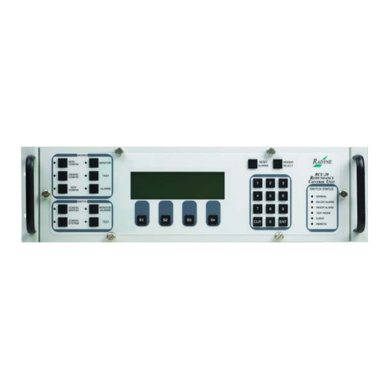
RCS20 M:N Redundancy Switch Revision 15 Introduction MN-RCS20 and CD-RCS20 1.3.1 RCU20 Redundancy Control Unit Front panel controls and indicators provide for auto/manual configuration, as well as display of online/off line status information for all modems in the Redundancy configuration. Figure 1-1 RCU20 Redundancy Control Unit –... -
Page 15: Digital Data Switch (Dds20) Configurations
RCS20 M:N Redundancy Switch Revision 15 Introduction MN-RCS20 and CD-RCS20 1.3.2 Digital Data Switch (DDS20) Configurations The DDS20 provides all of the data interconnections between the online and backup modems. The DDS20 also provides buffering of terrestrial data signals to backup modulators allowing ‘hot-standby’ modes of operation. -
Page 16: Figure 1-4 Universal Dds20 Digital Data Switch - Front Panel
RCS20 M:N Redundancy Switch Revision 15 Introduction MN-RCS20 and CD-RCS20 1.3.2.1 Universal DDS20 The Universal DDS20 has nine available slots supporting up to a 1:9 or 2:8 configuration. Figure 1-4 Universal DDS20 Digital Data Switch – Front Panel Figure 1-5 Universal DDS20 Digital Data Switch – Back Panel 1–4... -
Page 17: Figure 1-6 Dds20 Asi Or G703-M Digital Data Switch - Front Panel
RCS20 M:N Redundancy Switch Revision 15 Introduction MN-RCS20 and CD-RCS20 1.3.2.2 DDS20-ASI-M or DDS20-G703-M (Modulator-only) The DDS20-ASI-M or G703-M is a modulator-only configuration. Figure 1-6 DDS20 ASI or G703-M Digital Data Switch – Front Panel Figure 1-7 DDS20 ASI or G703-M Digital Data Switch – Back Panel 1–5... -
Page 18: Figure 1-8 Dds20-Asi-D Or Dds20-G.703-D Digital Data Switch - Front Panel
RCS20 M:N Redundancy Switch Revision 15 Introduction MN-RCS20 and CD-RCS20 1.3.2.3 DDS20-ASI or DDS20-G.703-D (Demodulator-only) The DDS20-ASI-D or DDS20-G.703-D is a demodulator-only configuration. Figure 1-8 DDS20-ASI-D or DDS20-G.703-D Digital Data Switch – Front Panel Figure 1-9 DDS20-ASI-D or DDS20-G.703-D Digital Data Switch – Back Panel 1–6... -
Page 19: Figure 1-10 Dds20-Gige Backup Switch - Front Panel
RCS20 M:N Redundancy Switch Revision 15 Introduction MN-RCS20 and CD-RCS20 1.3.2.4 DDS20-GigE (10/100/1000 Gigabit Ethernet) Backup Switch The DDS20-GigE Backup Switch configuration supports the DMD20, DMD50, DM240 and DD240 products. The Ethernet switch can support up to a 1:9 system. Figure 1-10 DDS20-GigE Backup Switch –... -
Page 20: Intermediate Frequency Switch (Ifs20) Configurations
RCS20 M:N Redundancy Switch Revision 15 Introduction MN-RCS20 and CD-RCS20 1.3.3 Intermediate Frequency Switch (IFS20) Configurations The IFS20 Intermediate Frequency Switch interfaces the IF signals of the modems with the Earth Station IF system and provides backup switching. The RCU20 can be configured with or without the IFS20. When the system does not require independent uplink and downlink ports, then the RCU20 will monitor the status of the primary modem and ensure backup when a primary modem faults. -
Page 21: Figure 1-14 L-Band (Transmit Only) Ifs20 Intermediate Frequency Switch - Front Panel
RCS20 M:N Redundancy Switch Revision 15 Introduction MN-RCS20 and CD-RCS20 1.3.3.2 L-Band IFS20 (Transmit Only) This IFS20 configuration is used for L-Band transmit only systems. Figure 1-14 L-Band (Transmit Only) IFS20 Intermediate Frequency Switch – Front Panel Figure 1-15 L-Band (Transmit Only) IFS20 Intermediate Frequency Switch – Back Panel 1–9... -
Page 22: Figure 1-16 L-Band (Transmit & Receive) Ifs20 Intermediate Frequency Switch - Front Panel
RCS20 M:N Redundancy Switch Revision 15 Introduction MN-RCS20 and CD-RCS20 1.3.3.3 L-Band IFS20 (Transmit & Receive) This IFS20 configuration is used for L-Band transmit and receive systems. Figure 1-16 L-Band (Transmit & Receive) IFS20 Intermediate Frequency Switch – Front Panel Figure 1-17 L-Band (Transmit &... -
Page 23: Chapter 2. Installation
RCS20 M:N Redundancy Switch Revision 15 Installation MN-RCS20 and CD-RCS20 Chapter 2. Installation Overview This chapter provides unpacking instructions, and instructions for installing an RCS20 M:N Redundancy Switch into a Satellite Modem system with cabling configurations for up to nine channels and nine transponders. -
Page 24: Test Data Sheet
RCS20 M:N Redundancy Switch Revision 15 Installation MN-RCS20 and CD-RCS20 M:N Switch to Modem Cable(s) for Backup Modulator and Demodulator • Test I/O Mating Connector • Optional 1:N Switch to Modem, I/O and Coaxial Cables for Modems 1 – 9 •... -
Page 25: Operating Environment
RCS20 M:N Redundancy Switch Revision 15 Installation MN-RCS20 and CD-RCS20 The IFS20A is also 8¾” (5 RU) high and is designed to be installed at the rear of a rack with the Up/Downconverter interface connections facing to the rear of the rack with the modem IF connections available in the interior of the rack. -
Page 26: Electrical
RCS20 M:N Redundancy Switch Revision 15 Installation MN-RCS20 and CD-RCS20 2.4.3 Electrical Make sure that the site has adequate electrical power. The power sources must be properly grounded and must be free from electrical interference as much as possible. If a redundant configuration is to be used, then each power cord on the RCS20 must be plugged into its own separate power circuit. -
Page 27: Connecting The Rcs20
RCS20 M:N Redundancy Switch Revision 15 Installation MN-RCS20 and CD-RCS20 2.4.3.2 Battery WARNING The RCS20 contains a Lithium Battery. DANGER OF EXPLOSION EXISTS if the battery is incorrectly replaced. Replace only with the same or equivalent type recommended by the manufacturer. -
Page 28: System Cabling Configuration
RCS20 M:N Redundancy Switch Revision 15 Installation MN-RCS20 and CD-RCS20 System Cabling Configuration See Appendix B for the cabling configurations between the RCS20 and its various companion products. The following figures are provided to illustrate the proper placement of the cables: Modem Checkout and Initial Power-Up The following descriptions assume that the RCS20 is installed in a suitable location with AC power applied to both slide out power supplies. -
Page 29: Chapter 3. Theory Of Operation
RCS20 M:N Redundancy Switch Revision 15 Theory of Operation MN-RCS20 and CD-RCS20 Chapter 3. Theory of Operation Overview This chapter provides additional basic information on the RCU20, DDS20, and IFS20 hardware and internal operation. RCU20 Major Assemblies The RCU20 Redundancy Control Unit contains the modules that control and monitor the operation of the M:N Switch System. -
Page 30: Clock Distribution Module (Optional)
RCS20 M:N Redundancy Switch Revision 15 Theory of Operation MN-RCS20 and CD-RCS20 3.2.4 Clock Distribution Module (Optional) Consult factory for availability. See Section 5.2.3.1. 3.2.5 Redundant Power Supplies The M:N Switch comes equipped with two fully redundant internal power supplies (PS1 and PS2) that supply DC voltage to the system. -
Page 31: If Switch Relays
RCS20 M:N Redundancy Switch Revision 15 Theory of Operation MN-RCS20 and CD-RCS20 3.3.1 IF Switch Relays The IFS20 contains 16 IF Switch Relays; eight uplink and eight downlink. The relays switch the IF signals to the Backup units. The signals to each downlink relay pass through a splitter with a loss of about 3.5 dB (including the loss due to energy splitting). -
Page 32: Rcs20 Channel Definitions
RCS20 M:N Redundancy Switch Revision 15 Theory of Operation MN-RCS20 and CD-RCS20 RCS20 Channel Definitions The RCS20 organized the modems connected to the switch according to satellite communications channels. These channels are labeled on the DDS20 and IFS20 panels, and are defined as follows: Channel 0 - Backup 1 Channel 1 - Modem 1 Channel 2 - Modem 2... -
Page 33: Chapter 4. User Interfaces
RCS20 M:N Redundancy Switch Revision 15 User Interfaces MN-RCS20 and CD-RCS20 Chapter 4. User Interfaces Operating Procedures Operation of the RCS20 consists of controlling the unit operating parameters and monitoring status and responses via one of the following control interfaces: Front Panel Interface •... -
Page 34: Modem Control Keys
RCS20 M:N Redundancy Switch Revision 15 User Interfaces MN-RCS20 and CD-RCS20 Feature Label Description LCD Front Panel Display. This is the 8 lines by 40 characters Liquid Crystal Display, (---) used to communicate with the RCS20. RESET Reset Alarms. This key resets all RCS20 current and latched major and minor alarms. ALARMS MODEM Select Current Modem. -
Page 35: Lcd Front Panel Display
RCS20 M:N Redundancy Switch Revision 15 User Interfaces MN-RCS20 and CD-RCS20 4.2.1.4 MODEM MONITOR Pressing this key brings up a series of menus on the LCD that allow the monitoring of status parameters for modems connected to the RCS20. This feature is presently not implemented on the RCS20. 4.2.1.5 MODEM TEST Pressing this key brings up a series of menus on the LCD that allow testing of the modems connected to... -
Page 36: Switch Status Leds
RCS20 M:N Redundancy Switch Revision 15 User Interfaces MN-RCS20 and CD-RCS20 4.2.5 Switch Status LEDs Refer to Table 4-2 for the description and colors of the Switch Status LEDs. 4.2.1.6 MODEM ALARMS. Table 4-2. Switch Status LED Function Color Description Normal Green Indicates that the unit is currently under power. -
Page 37: Switch Control Keys
RCS20 M:N Redundancy Switch Revision 15 User Interfaces MN-RCS20 and CD-RCS20 Table 4-4. Soft Key Function Description soft key Aborts loading values into memory and advances to the next screen in the menu tree. (‘NEXT’) soft key Aborts loading values into memory and advances to the previous screen in the menu tree. (‘PREVIOUS’) 4.2.8 Switch Control Keys The following keys, when pressed, control the RCS20 and decide which of the menu trees is displayed on... -
Page 38: Moving To The Next Screen In A Menu Tree
RCS20 M:N Redundancy Switch Revision 15 User Interfaces MN-RCS20 and CD-RCS20 what parameter is currently being edited. If there are several parameters on one screen, two of the soft keys will be labeled and . These keys are used to move the cursor from one parameter to the next, and therefore any of the configuration parameters displayed on the screen can be edited. -
Page 39: Front Panel Screens
RCS20 M:N Redundancy Switch Revision 15 User Interfaces MN-RCS20 and CD-RCS20 Front Panel Screens There are four menu trees used to control the RCS20: CONFIG SWITCH • CONFIG SYSTEM • MONITOR/ALARMS • TEST • These menu trees and their functions are discussed in the subsections that follow. NOTE The screens as depicted in the subsections that follow are representations. - Page 40 RCS20 M:N Redundancy Switch Revision 15 User Interfaces MN-RCS20 and CD-RCS20 2. Press <TOG MODE> to switch through the choices above. 3. Press <CLR> or <NEXT> to abort programming (no switch parameters changed). 4. Press <ENT> to load the information on the screen into the switch parameter table. Label Function Press to move the blinking cursor to the left.
- Page 41 RCS20 M:N Redundancy Switch Revision 15 User Interfaces MN-RCS20 and CD-RCS20 Label Function 1 through 0) to which the address is to be changed. Press to move the blinking cursor to the right. Used to select the modem (labeled Modems 1 through 0) to which the address is to be changed.
- Page 42 RCS20 M:N Redundancy Switch Revision 15 User Interfaces MN-RCS20 and CD-RCS20 Label Function Press to begin the test. As each modem is being tested, the screen will indicate astericks (**) at that location in the ACTIVE row. As the astericks move across the START screen, a ‘Y’...
- Page 43 RCS20 M:N Redundancy Switch Revision 15 User Interfaces MN-RCS20 and CD-RCS20 4.3.1.5 MODEM 9 / BACKUP 2 MODE MODEM 9 / <BACKUP> 2 CONFIGURATION MODE: BACKUP <BACKUP> <PREEMPT> <TRAFFIC> <RETURN> This screen allows the user to select the mode operation for Channel 9. The channel 9 modem can operate as a prime, a preemptable prime, or a dedicated backup.
- Page 44 RCS20 M:N Redundancy Switch Revision 15 User Interfaces MN-RCS20 and CD-RCS20 4.3.1.6 BACKUP MODE CONFIGURATION <BACKUP> MODE CONFIGURATION BACKUP 1 <BACKUP> MODE: MANUAL BACKUP 2 <BACKUP> MODE: MANUAL BU1 MODE BU2 MODE NEXT This screen displays the mode of backup operation for Backup Channels 1 and 2. If Channel 9 is configured as a prime channel, the selections for Backup Channel 2 will be unavailable.
- Page 45 RCS20 M:N Redundancy Switch Revision 15 User Interfaces MN-RCS20 and CD-RCS20 4.3.1.7 BACKUP MODE 1 SELECT <BACKUP> MODE CONFIGURATION BACKUP 1 <BACKUP> MODE: MANUAL <MANUAL> <NON-REV> <REVERT> <RETURN> This screen allows the user to select the mode of backup operation for Backup Channel 1 (Channel 0). The following backup modes are available: Manual - allows the operator to force backups to occur even if prime channel modems have not •...
- Page 46 RCS20 M:N Redundancy Switch Revision 15 User Interfaces MN-RCS20 and CD-RCS20 Label Function RETURN Pressed to return to the Backup Mode Configuration Screen. Press <CLR> or <RETURN> to abort programming (no switch parameters changed). Numeric Keypad Returns to the Backup Mode Configuration Screen. 4.3.1.8 BACKUP MODE 2 SELECT <BACKUP>...
- Page 47 (CnC) switching mode, Independent Switching should NOT be used. DoubleTalk is licensed from Raytheon Applied Signal Technology. ® DoubleTalk is a registered trademark of Raytheon Applied Signal Technology. ® Carrier-in-Carrier is a registered trademark of Comtech EF Data. ® 4–15...
- Page 48 RCS20 M:N Redundancy Switch Revision 15 User Interfaces MN-RCS20 and CD-RCS20 4.3.1.9.1 Programming steps: 1. Press or to move the blinking cursor the channel to be programmed 2. Press <TOG MODE> to toggle between U (linked switching) and M (independent switching). 3.
- Page 49 RCS20 M:N Redundancy Switch Revision 15 User Interfaces MN-RCS20 and CD-RCS20 L - indicates that a demodulator is programmed for automatic backup and is currently in “Looped • Back” standby. This means that the demodulator is looped to itself and is not locked to the actual Rx signal.
- Page 50 RCS20 M:N Redundancy Switch Revision 15 User Interfaces MN-RCS20 and CD-RCS20 4.3.1.11 AUTO MODE BACKUP 1 ASSIGNMENT PROGRAM AUTO MODE <BACKUP> ASSIGNMENT PROGRAM MODEM SET BU1 :md md md md md md md md <--- ---> TOG MODE RETURN The Auto Mode Backup 1 Assignment Program Subscreen allows the user to program the RCS20 Backup Channel 1 to provide automatic switching for any or all of the prime channel modems.
- Page 51 RCS20 M:N Redundancy Switch Revision 15 User Interfaces MN-RCS20 and CD-RCS20 Label Function Press to move the blinking cursor to the right. Used to select the modem (labeled Modems 1 through 8) to which the is to be changed. Used to toggle through the choices above.
- Page 52 RCS20 M:N Redundancy Switch Revision 15 User Interfaces MN-RCS20 and CD-RCS20 3. Select the desired Backup Channel 2 automatic backup assignments for each prime channel. 4. Press <CLR> or <NEXT> to abort programming (no switch parameters changed). 5. Press <ENT> to load the information on the screen into the Switch Parameter Table. Label Function Press to move the blinking cursor to the left.
- Page 53 RCS20 M:N Redundancy Switch Revision 15 User Interfaces MN-RCS20 and CD-RCS20 Label Function Numeric Keypad Used to enter the priority for the selected prime modem. 4.3.1.14 IFS20L DEMOD BKUP ASSIGNMENT SUMMARY AUTO MODE <BACKUP> ASSIGNMENT SUMMARY MODEM BU1-DEMOD : A BU2-DEMOD : E SET BU1 SET BU2...
- Page 54 RCS20 M:N Redundancy Switch Revision 15 User Interfaces MN-RCS20 and CD-RCS20 4.3.1.15 LEARN/BACKUP TEST CONFIGURATION LEARN/BACKUP TEST CONFIGURATION (*=ConfigChanged, F=BackupTestFailed) MODEM LEARNED :** md md md md md md md md md BU1 TEST BU2 TEST LEARN TEST COPY NEXT This screen displays modem learn state and backing test status.
- Page 55 RCS20 M:N Redundancy Switch Revision 15 User Interfaces MN-RCS20 and CD-RCS20 Label Function Press to cycle down through the modem test options (ALL, MODEM9, MODEM8 - DOWN MODEM0). CANCEL Press to cycle back to the LEARN/BACKUP TEST CONFIGURATION Screen. Press <ENT> to accept the selection from S1 and S2. Numeric Keypad Press <CLR>...
- Page 56 RCS20 M:N Redundancy Switch Revision 15 User Interfaces MN-RCS20 and CD-RCS20 4.3.1.18 COPY MODEM CONFIGURATION COPY MODEM CONFIGURATION <ENT> to accept, <CLR> to abort. COPY FROM : MODEM1 COPY TO MODEM8 CURSOR DOWN CANCEL This screen allows the user to copy configurations between (from/to) modems. Label Function CURSOR...
- Page 57 RCS20 M:N Redundancy Switch Revision 15 User Interfaces MN-RCS20 and CD-RCS20 reaches fault delay seconds. The fault delay can be from 0.0 seconds to 199.9 seconds for each of the modulators (each modulator may be set to a different time delay if desired). 4.3.1.19.1 Programming steps: 1.
- Page 58 RCS20 M:N Redundancy Switch Revision 15 User Interfaces MN-RCS20 and CD-RCS20 4.3.1.20.1 Programming steps: 1. Press or to move the blinking cursor the prime channel to be programmed. 2. Use the numeric keypad to enter the demodulator fault delay for the selected prime channel. 3.
- Page 59 RCS20 M:N Redundancy Switch Revision 15 User Interfaces MN-RCS20 and CD-RCS20 3. Select the desired demodulator acquisition delays for each prime channel (each demodulator may be set to a different time delay if desired). 4. Press <CLR> or <NEXT> to abort programming (no switch parameters changed). 5.
- Page 60 RCS20 M:N Redundancy Switch Revision 15 User Interfaces MN-RCS20 and CD-RCS20 4. Press <ENT> to load the information on the screen into the switch parameter table. Switching will occur immediately after pressing <ENT>. IMPORTANT SET BU2 will be unavailable if Channel 9 is configured as a prime channel. Label Function Selects Backup Unit 1 for change and cycles to the FORCE MANUAL BACKUP 1...
- Page 61 RCS20 M:N Redundancy Switch Revision 15 User Interfaces MN-RCS20 and CD-RCS20 4. Press <ENT> to load the information on the screen into the switch parameter table. Switching will occur immediately after pressing <ENT>. Label Function Press to place the blinking cursor on MODULATOR. DEMOD Press to place the blinking cursor on DEMODULATOR.
-
Page 62: Config System Menu Tree
RCS20 M:N Redundancy Switch Revision 15 User Interfaces MN-RCS20 and CD-RCS20 Label Function RETURN Press to return to the AUTO MODE BACKUP ASSIGNMENT SUMMARY Screen. Used to enter the prime channel number to switch to Backup Channel 2. Press <CLR> or <NEXT> to abort programming (no switch parameters changed). Numeric Keypad Press <ENT>... - Page 63 RCS20 M:N Redundancy Switch Revision 15 User Interfaces MN-RCS20 and CD-RCS20 Label Function Press <NEXT> to advance to next screen. Numeric Keypad Press <CLR> to return to previous screen. 4.3.2.2 TERMINAL PORT CONFIGURATION TERMINAL PORT CONFIGURATION TERMINAL BAUD RATE : 19200 TERMINAL EMULATION : VT 100 BAUD EMUL...
- Page 64 RCS20 M:N Redundancy Switch Revision 15 User Interfaces MN-RCS20 and CD-RCS20 Label Function NEXT Press to cycle to the next screen. Numeric Keypad 4.3.2.3 TERMINAL PORT BAUD RATE TERMINAL PORT BAUD RATE BAUD RATE: 19200 19200 9600 2400 CANCEL This subscreen allows the user to modify the RCS20 terminal port baud rate. 4.3.2.3.1 Programming steps: 1.
- Page 65 RCS20 M:N Redundancy Switch Revision 15 User Interfaces MN-RCS20 and CD-RCS20 4.3.2.4 TERMINAL PORT EMULATION TERMINAL PORT EMULATION TERMINAL EMULATING: VT100 ADDS VP VT100 WYSESO RETURN This subscreen allows the user to modify the RCS20 terminal port terminal emulation. 4.3.2.4.1 Programming steps: 1.
- Page 66 RCS20 M:N Redundancy Switch Revision 15 User Interfaces MN-RCS20 and CD-RCS20 4.3.2.5 REMOTE PORT CONFIGURATION REMOTE PORT CONFIGURATION RCU20 REMOTE PORT BAUD RATE : 1200 RCU20 REMOTE PORT ADDRESS : 32 RCU20 REMOTE PORT PROTOCOL : RLLP BAUD ADDR PROTOCOL NEXT This screen displays the Remote Port Baud Rate, the Remote Port Address, and the Terminal Emulation Type, and allows the user to cycle to Subscreens to change the configurations.
- Page 67 RCS20 M:N Redundancy Switch Revision 15 User Interfaces MN-RCS20 and CD-RCS20 4.3.2.6 REMOTE PORT BAUD RATE CONFIGURATION REMOTE PORT BAUD RATE CONFIGURATION RCU20 REMOTE PORT BAUD RATE : 1200 1200 2400 4800 NEXT This subscreen allows the user to modify the Remote Port Baud Rate. 4.3.2.6.1 Programming steps: Select either <115200>, <57600>, <38400>, <19200>, <9600>, <4800>, <2400>, or <1200>...
- Page 68 RCS20 M:N Redundancy Switch Revision 15 User Interfaces MN-RCS20 and CD-RCS20 4.3.2.7 REMOTE PORT ADDRESS REMOTE PORT ADDRESS : RETURN This subscreen allows the user to modify the RCS20 remote port baud address. 4.3.2.7.1 Programming steps: Use the numeric keypad to enter the desired multi-drop address for the RCS20. Valid addresses are 32 through 255.
- Page 69 RCS20 M:N Redundancy Switch Revision 15 User Interfaces MN-RCS20 and CD-RCS20 4.3.2.8 REMOTE PORT PROTOCOL CONFIGURATION MODEM PORT PROTOCOL CONFIGURATION MODEM MODEM PORT PROTOCOL : 9600 BAUD NEXT This subscreen allows the user to modify the modem remote port communication protocol. The remote port protocol determines the binary format for communication between the RCU20 and all modems connected to the RCU20.
- Page 70 RCS20 M:N Redundancy Switch Revision 15 User Interfaces MN-RCS20 and CD-RCS20 4.3.2.9 MODEM PORT CONFIGURATION MODEM PORT CONFIGURATION RCU20 MODEM PORT BAUD RATE : 9600 BAUD NEXT This screen displays the Remote Port Baud Rate and allows the user to cycle to Subscreens to change the configurations.
- Page 71 RCS20 M:N Redundancy Switch Revision 15 User Interfaces MN-RCS20 and CD-RCS20 4.3.2.10 MODEM PORT BAUD RATE CONFIGURATION MODEM PORT BAUD RATE CONFIGURATION RCU20 MODEM PORT BAUD RATE : 1200 9600 19200 38400 57600 This subscreen allows the user to modify the Modem Port Baud Rate. 4.3.2.10.1 Programming steps: Select either <9600>, <19200>, <38400>, or <57600>...
- Page 72 RCS20 M:N Redundancy Switch Revision 15 User Interfaces MN-RCS20 and CD-RCS20 4.3.2.11 KEY CLICK CONFIGURATION KEY CLICK CONFIGURATION KEY CLICK : NEXT This screen allows the user to turn on/off the audible key click that is heard with every key press on the front panel.
-
Page 73: Set Date
RCS20 M:N Redundancy Switch Revision 15 User Interfaces MN-RCS20 and CD-RCS20 Press <TIME> to cycle to the SET TIME Subscreen. Label Function DATE Press to cycle to the SET DATE Subscreen. TIME Press to cycle to the SET TIME Subscreen. NEXT Press to cycle to the next screen. -
Page 74: Set Time
RCS20 M:N Redundancy Switch Revision 15 User Interfaces MN-RCS20 and CD-RCS20 4.3.2.14 SET TIME SET TIME TIME : 09:l5:59 <--- ---> DOWN This subscreen allows the user to configure the real-time clock function for the RCS20. 4.3.2.14.1 Programming steps: Press or to move the blinking cursor the hour, minute, or second. Press <UP>... - Page 75 RCS20 M:N Redundancy Switch Revision 15 User Interfaces MN-RCS20 and CD-RCS20 4.3.2.15 LCD CONTRAST ADJUSTMENT LCD CONTRAST ADJUSTMENT +----------------------------+ : ABCDEFGHIJKLMNOPQRSTUVWXYZ : +----------------------------+ DOWN NEXT This screen allows the user to adjust the contrast of the characters on the LCD screen. The switch parameter table is immediately updated upon any changes.
- Page 76 RCS20 M:N Redundancy Switch Revision 15 User Interfaces MN-RCS20 and CD-RCS20 4.3.2.16.1 Programming steps: Use the numeric keypad to enter the desired backlight timeout value in seconds. Valid values are 0 to 255 seconds. Press <CLR> or <NEXT> to abort programming (no switch parameters changed). Press <ENT>...
- Page 77 RCS20 M:N Redundancy Switch Revision 15 User Interfaces MN-RCS20 and CD-RCS20 4.3.2.18 IFS BANK CONTROLLER IFS BANK CONTROLLER DISABLE IFS: TOG MODE RETURN This screen allows the user to disable IFS. Label Function TOG MODE Press to toggle between NO and YES. RETURN Press to return to the BANK CONTROL CONFIGURATION Screen.
- Page 78 RCS20 M:N Redundancy Switch Revision 15 User Interfaces MN-RCS20 and CD-RCS20 4.3.2.20 COMBINE IFL (IFS L-Band Demodulator Only) COMBINE DEMOD IFL COMBINE IFL: TOG MODE RETURN This screen allows the user to combine the IFS L-Band (enable 8-input mode) or return the switch to its original 2x4 (enable 4-input mode) configuration.
- Page 79 RCS20 M:N Redundancy Switch Revision 15 User Interfaces MN-RCS20 and CD-RCS20 4.3.2.21.1 Programming Steps for setting up the link: Establish a link from the prime channel to the far end modem using TX IF = RX IF and CnC Learn Prime Modem Test Prime Modem Set BU modem to IF LOOPBACK Verify no alarms...
- Page 80 RCS20 M:N Redundancy Switch Revision 15 User Interfaces MN-RCS20 and CD-RCS20 4.3.2.22 CnC SWITCHING CARRIER-IN-CARRIER MODEMS CNC SWITCHING: TOG MODE RETURN This screen is the actual location where the user can configure the CnC Switching Mode. Label Function TOG MODE Press to toggle between NO and YES.
- Page 81 RCS20 M:N Redundancy Switch Revision 15 User Interfaces MN-RCS20 and CD-RCS20 4.3.2.24 REFERENCE DISTRIBUTION CONFIGURATION REFERENCE DISTRIBUTION CONFIGURATION NO RDM PRESENT FALLBACK : EXTA ONLY INTERNAL FREQ : 10.0 MHZ ( ‘***’ INDICATES CURRENT SOURCE) FALL FREQ NEXT This screen displays the configuration of the optional Reference Distribution Module Expansion Card (RDM), located at the rear of the RCU20.
- Page 82 RCS20 M:N Redundancy Switch Revision 15 User Interfaces MN-RCS20 and CD-RCS20 4.3.2.25 RDM FALLBACK CONFIGURATION RDM INTERNAL REFERENCE CONFIGURATION FALLBACK : EXTA ONLY TOG MODE RETURN This screen allows the user to configure the fallback programming for the optional Reference Distribution Module (RDM).
- Page 83 RCS20 M:N Redundancy Switch Revision 15 User Interfaces MN-RCS20 and CD-RCS20 4.3.2.26 RDM FALLBACK CONFIGURATION RDM INTERNAL REFERENCE CONFIGURATION INTERNAL FREQ : 10.0 MHZ TOG MODE RETURN This screen allows the user to configure the RDM Internal Reference Frequency. The internal frequencies may be one of the following: •...
- Page 84 RCS20 M:N Redundancy Switch Revision 15 User Interfaces MN-RCS20 and CD-RCS20 4.3.2.27 MODEM SERVICE MODE MODEM SERVICE MODE (N = Normal, S = Service) BACKUP : MODEM SERVICE: N SERVICE NEXT This screen displays the modem service mode: N - Normal •...
- Page 85 RCS20 M:N Redundancy Switch Revision 15 User Interfaces MN-RCS20 and CD-RCS20 Label Function Press to move the blinking cursor to the left. Used to select the modem for the service selection. Used to toggle between N and S. MODE RETURN Press to cycle back to the MODEM SERVICE MODE Screen.
-
Page 86: Monitor/Alarms Menu Tree
RCS20 M:N Redundancy Switch Revision 15 User Interfaces MN-RCS20 and CD-RCS20 4.3.3 MONITOR/ALARMS Menu Tree 4.3.3.1 EXPANSION SLOT MONITOR EXPANSION SLOT MONITOR SLOT 0: (EMPTY) SLOT 1: USER INTERFACE SLOT 2: BANK CONTROL:(IFS20A, DDS20) SLOT 3: (EMPTY) SLOT 4: (EMPTY) SLOT 5: UNKNOWN TYPE NEXT... - Page 87 RCS20 M:N Redundancy Switch Revision 15 User Interfaces MN-RCS20 and CD-RCS20 “.” - A period indicates that the modulator or demodulator is reporting status normal. • F - Indicates that the modulator or demodulator is reporting failure status. • ? - Indicates that the status monitor for a channel on the DDS20 is either missing or •...
- Page 88 RCS20 M:N Redundancy Switch Revision 15 User Interfaces MN-RCS20 and CD-RCS20 Label Function NEXT Press to cycle to the next Events Screen. Numeric Keypad 4.3.3.4 NEXT EVENTS SCREEN Label Function DELALL Press to delete all stored events. NEXT Press to cycle to the next screen. Numeric Keypad 4.3.3.5 SWITCH MAJOR ALARMS 1...
- Page 89 RCS20 M:N Redundancy Switch Revision 15 User Interfaces MN-RCS20 and CD-RCS20 Press <TOG MODE> to toggle between YES and NO. ‘Y’ indicates an alarm is masked, ‘N’ indicates an alarm is not masked. Press <CLR> or <NEXT> to abort programming (no switch parameters changed). Press <ENT>...
- Page 90 RCS20 M:N Redundancy Switch Revision 15 User Interfaces MN-RCS20 and CD-RCS20 4.3.3.7 SWITCH MINOR ALARMS 1 SWITCH MINOR ALARMS MASK POWER SUPPLY 1 PRESENT : FAIL POWER SUPPLY 1 VOLTAGE : FAIL POWER SUPPLY 2 PRESENT : PASS POWER SUPPLY 2 VOLTAGE : PASS TOG MODE NEXT...
-
Page 91: Test Menu Tree
RCS20 M:N Redundancy Switch Revision 15 User Interfaces MN-RCS20 and CD-RCS20 4.3.3.8 SWITCH MINOR ALARMS 2 SWITCH MINOR ALARMS MASK COMMUNICATIONS : PASS PRIME MODEM STATUS : FAIL BACKUP MODEM STATUS : PASS PRIME MODEM CONFIGURATION : FAIL TOG MODE NEXT ... - Page 92 RCS20 M:N Redundancy Switch Revision 15 User Interfaces MN-RCS20 and CD-RCS20 SYSTEM COMMUNICATION TEST - tests modem channel connections. • MODEM PARAMETER COMPATIBILITY TEST - tests modem parameter compatibility (this test • is currently under development). LAMP TEST - tests the operation of all LEDs on the front panel. •...
- Page 93 RCS20 M:N Redundancy Switch Revision 15 User Interfaces MN-RCS20 and CD-RCS20 Label Function START Press to start test. RETURN Press to cycle back to the SWITCH SYSTEM TESTS Screen. Numeric Keypad 4.3.4.3 MODEM PARAMETER COMPATIBILITY TEST MODEM PARAMETER COMPATIBILITY TEST MODEM BU1-MANUAL:md md md md md md md md md md BU2-MANUAL:md md md md md md md md md md...
-
Page 94: Lamp Test
RCS20 M:N Redundancy Switch Revision 15 User Interfaces MN-RCS20 and CD-RCS20 4.3.4.4 LAMP TEST LAMP TEST PRESS THE ‘START SOFTKEY TO ILLUMINATE ALL FRONT PANEL LEDS FOR 5 SECONDS. <START> RETURN This screen allows the user to test all LED lamps on the front panel of the RCU20 for five seconds. Label Function START... -
Page 95: Remote Interface
RCS20 M:N Redundancy Switch Revision 15 User Interfaces MN-RCS20 and CD-RCS20 4.3.4.6 REMOTE PORT TEST REMOTE PORT TEST Remote test will send ASCII characters ‘Test’ to remote port each time the softkey labeled ‘Test’ is pressed. <TEST> <RETURN> This screen allows the user to send an ASCII test string out of the remote port. 4.3.4.6.1 Programming steps: Press <TEST>... -
Page 96: Terminal Port Control
RCS20 M:N Redundancy Switch Revision 15 User Interfaces MN-RCS20 and CD-RCS20 Terminal Port Control The RCS20 has a dedicated RS-232 serial port (Terminal Port) for use with a separate terminal or computer running a terminal emulation program. The Terminal Port is a 9-Pin female ‘D’ sub connector J2 located at the rear of the unit on the Switch Interface plug in module. -
Page 97: Channel Status
RCS20 M:N Redundancy Switch Revision 15 User Interfaces MN-RCS20 and CD-RCS20 1.Main Menu 11.Ch 0 Config :BACKUP 21.Force Mod BU1:0 2.Control Mode:FT PANEL 12.Ch 9 Config :TRAFFIC 22.Force Dmd BU1:0 3.Remote Mode :RLLP 13.BU1 BU Mode :MANUAL 23.Force Mod BU2:0 4.Remote Addr :32 14.BU2 BU Mode :MANUAL... -
Page 98: Figure 4-5. Terminal Submenu 3
RCS20 M:N Redundancy Switch Revision 15 User Interfaces MN-RCS20 and CD-RCS20 1.Main Menu 21.Reset Alarms 2.Control Mode:FT PANEL 3.Remote Mode :RLLP 4.Remote Addr :32 5.Remote Baud :9600 ------------------------------- ALARMS -------------------------------------- MAJOR ALARMS MASK LATCH MINOR ALARMS MASK LATCH 30.RAM/ROM PASS PASS 40.PS1 Present PASS... -
Page 99: Chapter 5. Electrical Interfaces
RCS20 M:N Redundancy Switch Revision 15 Electrical Interfaces MN-RCS20 and CD-RCS20 Chapter 5. Electrical Interfaces Overview This chapter describes the interfaces available on the RCS20 M:N Redundancy Switch System (Figure 5-1). All RCS20 connections (including the RCU20 and various configurations of the DDS20 and IFS20) are made to labeled connectors located on the back panel of the RCU (Figure 5-2). -
Page 100: Rcu20 Back Panel Connectors
RCS20 M:N Redundancy Switch Revision 15 Electrical Interfaces MN-RCS20 and CD-RCS20 RCU20 Back Panel Connectors Figure 5-2 RCS20 Connectors 5.2.1 Slide-Out Redundant Power Supply/Switch Modules WARNING Dangerous AC voltages exist inside of the RCS20 when either one of the AC Plug- in Switch Modules are enabled or plugged in. -
Page 101: Expansion Slots
RCS20 M:N Redundancy Switch Revision 15 Electrical Interfaces MN-RCS20 and CD-RCS20 5.2.3 Expansion Slots There are six expansion slots (numbered 0 through 5). The following cards may be inserted into the slots, as shown in Figure 5-2: Reference Distribution Module (shown installed in Slot 0) •... -
Page 102: Figure 5-4 Reference Distribution Module Jumper Settings
RCS20 M:N Redundancy Switch Revision 15 Electrical Interfaces MN-RCS20 and CD-RCS20 The Reference Distribution Module must be configured with two jumpers to select the termination impedance. The jumpers, J1 and J2, are shown in Figure 5-4. Figure 5-4 Reference Distribution Module Jumper Settings Set the jumpers according to the following table to get the required termination impedance: Termination Impedance (Ohms) Pins 1 and 2 Shorted... - Page 103 RCS20 M:N Redundancy Switch Revision 15 Electrical Interfaces MN-RCS20 and CD-RCS20 5.2.3.1.2 J2 | EXT B IN (External Input B) Impedance 50, 75, 510 Ohms (Jumper-Selectable) Frequency 1.25, 2.5, 5.0 and 10.0 MHz Input Level High-Level 2 to 5 Volt Specification Low-Level 0 to 0.8 Volts 5.2.3.1.3...
-
Page 104: Figure 5-5 Cpu Terrestrial I/O Card
RCS20 M:N Redundancy Switch Revision 15 Electrical Interfaces MN-RCS20 and CD-RCS20 5.2.3.2 CPU Terrestrial I/O Card Figure 5-5 CPU Terrestrial I/O Card 5.2.3.2.1 J1 | ALARMS The J1 | ALARMS port is a 9-Pin Type D Female Connector. This port has relay contacts that trigger various switch faults. -
Page 105: Figure 5-6 Bank Control I/O Card
RCS20 M:N Redundancy Switch Revision 15 Electrical Interfaces MN-RCS20 and CD-RCS20 Ground No Connection Output Input No Connection 5.2.3.2.3 J3 | REMOTE The J3 | REMOTE EIA-485 Remote Interface port is a 9-Pin Type D Female Connector. It is used to monitor and control switch functions and modems via an M&C designed based on the RLLP. - Page 106 RCS20 M:N Redundancy Switch Revision 15 Electrical Interfaces MN-RCS20 and CD-RCS20 5.2.3.2.4 J1 | MODEM REMOTE The J1 | MODEM REMOTE EIA-485 Control port is a 9-Pin Type D Female Connector. It is used as an RS485 bus to interface to the modems remote ports Pin No.
-
Page 107: Dds20 Universal Modem Data Switch
RCS20 M:N Redundancy Switch Revision 15 Electrical Interfaces MN-RCS20 and CD-RCS20 Pin No. Signal Name Signal Direction Relay +6 Volts VCC_RELAY Output Serial Control Data 2 DDS_LDAT2 Bidirectional Ground Ground Logic +5 Volts Output Relay +6 Volts VCC_RELAY Output Relay +6 Volts VCC_RELAY Output Ground... -
Page 108: Figure 5-8 Front Panel Interface - Dds20 Data Switch Module
RCS20 M:N Redundancy Switch Revision 15 Electrical Interfaces MN-RCS20 and CD-RCS20 5.3.1.1 DDS20 Data Switch Module Figure 5-8 Front Panel Interface – DDS20 Data Switch Module Two part numbers exist for Data Switch Modules on the DDS20: AS/3356 (Figure 5-9) and AS/3478 (Figure 5-10 for the 6-position DIP Switch version, and Figure 5-11 for the 8-position DIP Switch version). -
Page 109: Figure 5-9 As/3356 Data Switch Module
RCS20 M:N Redundancy Switch Revision 15 Electrical Interfaces MN-RCS20 and CD-RCS20 5.3.1.1.1 Configuring Data Switch Module DIP Switches Figure 5-9 AS/3356 Data Switch Module Table 5-1. AS/3356 G.703 Unbalanced DIP Switch Settings Setting Table 5-2 AS/3356 G.703 Balanced DIP Switch Settings Setting 5–11... -
Page 110: Table 5-3 As/3356 All Sync (Eia-422/V.35) Dip Switch Settings
RCS20 M:N Redundancy Switch Revision 15 Electrical Interfaces MN-RCS20 and CD-RCS20 Setting Table 5-3 AS/3356 ALL SYNC (EIA-422/V.35) DIP Switch Settings Setting 5–12... -
Page 111: Figure 5-10 As/3478 Data Switch Module
RCS20 M:N Redundancy Switch Revision 15 Electrical Interfaces MN-RCS20 and CD-RCS20 Figure 5-10 AS/3478 Data Switch Module Table 5-4. AS/3478 G.703 Balanced DIP Switch Settings Setting Table 5-5. AS/3478 G.703 Balanced DIP Switch Settings Setting 5–13... -
Page 112: Figure 5-11 As/3478 Data Switch Module (For A2 Forward Only)
RCS20 M:N Redundancy Switch Revision 15 Electrical Interfaces MN-RCS20 and CD-RCS20 Figure 5-11 AS/3478 Data Switch Module (for A2 Forward Only) Table 5-6. AS/3356 G.703 Unbalanced DIP Switch Settings Setting Table 5-7. AS/3356 G.703 Balanced DIP Switch Settings Setting 5–14... -
Page 113: Table 5-8. As/3356 Eia-422/V.35 Dip Switch Settings
RCS20 M:N Redundancy Switch Revision 15 Electrical Interfaces MN-RCS20 and CD-RCS20 Table 5-8. AS/3356 EIA-422/V.35 DIP Switch Settings Setting 5.3.1.1.2 DDS20 Data Switch Module Connectors 5.3.1.1.2.1 J1 | SD (Send Data) The J1 | SD G.703 Unbalanced Send Data port is a 75 Ohm female BNC Connector. 5.3.1.1.2.2 J2 | DDO (Drop Data Out) The J2 | DDO Unbalanced Drop Data Out port is a 75 Ohm female BNC Connector. -
Page 114: Table 5-9. J6 | Es/Es 9-Pin Type D Female Connector (For Use With Dmd20/Dmd50)
RCS20 M:N Redundancy Switch Revision 15 Electrical Interfaces MN-RCS20 and CD-RCS20 Pin No. Signal Description Direction Description Direction ESCAUDRX 2A Rx Audio 2A Output Rx Clock 64K A Output 5.3.1.1.2.6 J9 | ES/ES (Earth Station-to-Earth Station) The J9 | ES/ES Earth-Station-to-Earth-Station port is a 9-Pin Type D Female Asynchronous Data Connector. - Page 115 RCS20 M:N Redundancy Switch Revision 15 Electrical Interfaces MN-RCS20 and CD-RCS20 Pin No. Signal Name Signal Direction No Connection Backward Alarm Out-4 NO ESCBWO 4 NO Ground Backward Alarm Out-4 NO ESCBWO 4 NO No Connection Backward Alarm In 2 ESCBWI 2 Input Backward Alarm In 4...
- Page 116 RCS20 M:N Redundancy Switch Revision 15 Electrical Interfaces MN-RCS20 and CD-RCS20 Pin No. Signal Name Signal Direction Tx Clock-B (+) ESCTXC-B Output Tx Octet-B (+) ESCTXO-B Output 5.3.1.1.2.9 J9 | G.703 (G.703 Balanced) The J9 | G.703 Balanced Interface port is a 15-Pin Type D Female Connector Pin No.
- Page 117 RCS20 M:N Redundancy Switch Revision 15 Electrical Interfaces MN-RCS20 and CD-RCS20 Pin No. Signal Name Signal Direction No Connection Receiver Ready A (-) RR-A Output No Connection External Clock A (-) BAL EXC-A Input Receive Octet A (-) RX-0-A Output Terminal Timing A (-) TT-A Input...
-
Page 118: Dds20 - Universal Switch Back Panel Connectors
RCS20 M:N Redundancy Switch Revision 15 Electrical Interfaces MN-RCS20 and CD-RCS20 5.3.2 DDS20 – Universal Switch Back Panel Connectors Figure 5-12 DDS20 Universal Switch – Back Panel Connectors 5.3.2.1 J1 | MODEM 1 through J8 | MODEM 8 68-Pin High Density Min DSUB Female Connectors Each connector, J1 | MODEM 1 through J8 | MODEM 8, connects to each prime modem. - Page 119 RCS20 M:N Redundancy Switch Revision 15 Electrical Interfaces MN-RCS20 and CD-RCS20 Pin No. Signal Name Signal Direction IDR ESC Backward Alarm Input - 3 ESCBWI 3 IBS ES Transmit Data A IDR ESC Backward Alarm Input 1 TXD-A BWI 1 Input Mod Fault Open Collector Output MOD FLT...
- Page 120 RCS20 M:N Redundancy Switch Revision 15 Electrical Interfaces MN-RCS20 and CD-RCS20 Pin No. Signal Name Signal Direction IDR ESC Transmit 8 Kbps Output Data B ESCTXD-B Input IDR ESC Receive 8 Kbps Clock Output B ESCRXC-B Output IDR ESC Receive 8 Kbps Data Output B ESCRXD-B Output IDR ESC Backward Alarm Out 4 Normally Open...
-
Page 121: Gige (10/100/1000 Ethernet) Backup Switch
RCS20 M:N Redundancy Switch Revision 15 Electrical Interfaces MN-RCS20 and CD-RCS20 DDS-20 GigE (10/100/1000 Ethernet) Backup Switch 5.4.1 DDS-20 – GigE Switch Front Panel Connectors Figure 5-13 DDS GigE Switch – Front Panel Connectors 5.4.1.1 J1 | CH1 DATA IN through J9 | CH 9 DATA IN The J1 | CH1 DATA IN through J9 | CH9 DATA IN ports are RJ-45, 10/100/1000 Ethernet Data ports for connecting channels 1 through 9. - Page 122 RCS20 M:N Redundancy Switch Revision 15 Electrical Interfaces MN-RCS20 and CD-RCS20 Prime Modem 5 Fault Prime Modem 6 Fault Prime Modem 7 Fault Prime Modem 8 Fault Prime Modem 9 Fault Backup Modem 1 Fault No Connection No Connection No Connection No Connection Ground 5.4.2.4...
-
Page 123: Ifs20 Intermediate Frequency Switch Units
RCS20 M:N Redundancy Switch Revision 15 Electrical Interfaces MN-RCS20 and CD-RCS20 IFS20 Intermediate Frequency Switch Units 5.5.1 IFS20 70/140 MHz Unit 5.5.1.1 IFS20 70/140 MHz Unit Connectors – Front Panel The IFS20 has connections to both the front and back panels (Figures 5-15 and 5-16). Unless otherwise indicated, all IF connectors are 75 Ohm Female BNC connectors. - Page 124 RCS20 M:N Redundancy Switch Revision 15 Electrical Interfaces MN-RCS20 and CD-RCS20 5.5.1.1.7 J7 | UP6 The J7 | UP6 port is used for connecting satellite transmission channel 6 to an up converter or combiner. 5.5.1.1.8 J8 | UP7 The J8 | UP7 port is used for connecting satellite transmission channel 7 to an up converter or combiner. 5.5.1.1.9 J9 | UP8 The J9 | UP8 port is used for connecting satellite transmission channel 8 to an up converter or combiner.
-
Page 125: Figure 5-16 Ifs20 Back Panel Connectors
RCS20 M:N Redundancy Switch Revision 15 Electrical Interfaces MN-RCS20 and CD-RCS20 5.5.1.1.17 J29 | DN4 The J29 | DN4 port is used for connecting a down converter or splitter for satellite receive channel 4. 5.5.1.1.18 J30 | DN5 The J30 | DN5 port is used for connecting a down converter or splitter for satellite receive channel 5. 5.5.1.1.19 J31 | DN6 The J31 | DN6 port is used for connecting a down converter or splitter for satellite receive channel 6. - Page 126 RCS20 M:N Redundancy Switch Revision 15 Electrical Interfaces MN-RCS20 and CD-RCS20 5.5.1.2.4 J15 | MOD 2 The J15 | MOD 2 Input port is used for connecting to the prime modem 2 transmit IF. 5.5.1.2.5 J16 | MOD 3 The J16 | MOD 3 Input port is used for connecting to the prime modem 3 transmit IF. 5.5.1.2.6 J17 | MOD 4 The J17 | MOD 4 Input port is used for connecting to the prime modem 4 transmit IF.
- Page 127 RCS20 M:N Redundancy Switch Revision 15 Electrical Interfaces MN-RCS20 and CD-RCS20 5.5.1.2.15 J36 | DMD3 The J36 | DMD3 port is used for connecting to the prime modem 3 receive IF. 5.5.1.2.16 J37 | DMD4 The J37 | DMD4 port is used for connecting to the prime modem 4 receive IF. 5.5.1.2.17 J38 | DMD5 The J38 | DMD5 port is used for connecting to the prime modem 5 receive IF.
-
Page 128: Ifs20L L-Band Unit
RCS20 M:N Redundancy Switch Revision 15 Electrical Interfaces MN-RCS20 and CD-RCS20 5.5.2 IFS20L L-Band Unit The IFS20L has connections to both the front and back panels (shown in Figures 5-17 and 5-18). Unless otherwise indicated, all L-Band connectors are 50 Ohm Female SMA connectors. 5.5.2.1 IFS20L L-Band Unit Connectors –... - Page 129 RCS20 M:N Redundancy Switch Revision 15 Electrical Interfaces MN-RCS20 and CD-RCS20 5.5.2.1.7 J19 | MODEM 6 The J19 | MODEM 6 port is used for connecting to the prime modem 6 L-Band transmit port. 5.5.2.1.8 J20 | MODEM 7 The J20 | MODEM 7 port is used for connecting to the prime modem 7 L-Band transmit port. 5.5.2.1.9 J21 | MODEM 8 The J21 | MODEM 8 port is used for connecting to the prime modem 8 L-Band transmit port.
-
Page 130: Figure 5-18 Ifs20L Back Panel Connectors
RCS20 M:N Redundancy Switch Revision 15 Electrical Interfaces MN-RCS20 and CD-RCS20 5.5.2.1.17 J29 | DOWN CONVERTER PORT H J29 | DOWN CONVERTER PORT H is used for connecting to a downlink feed for mapped satellite receive channels 1 thru 8. 5.5.2.1.18 J30 | DOWN CONVERTER PORT E J30 | DOWN CONVERTER PORT E is used for connecting to a downlink feed for mapped satellite... - Page 131 RCS20 M:N Redundancy Switch Revision 15 Electrical Interfaces MN-RCS20 and CD-RCS20 5.5.2.2.6 J6 | UPCONV4 The J6 | UPCONV 4 port is used for connecting satellite transmit channel 4 to uplink. 5.5.2.2.7 J7 | UPCONV3 The J7 | UPCONV 3 port is used for connecting satellite transmit channel 3 to uplink. 5.5.2.2.8 J8 | UPCONV2 The J8 | UPCONV 2 port is used for connecting satellite transmit channel 2 to uplink...
- Page 132 RCS20 M:N Redundancy Switch Revision 15 Electrical Interfaces MN-RCS20 and CD-RCS20 BLANK PAGE 5–34...
-
Page 133: Chapter 6. Maintenance And Troubleshooting
RCS20 M:N Redundancy Switch Revision 15 Maintenance and Troubleshooting MN-RCS20 and CD-RCS20 Chapter 6. Maintenance and Troubleshooting Periodic Maintenance There are two external fuses in each power supply module located in a slide out drawer just to the left of the power switch. -
Page 134: Active Major Alarms
RCS20 M:N Redundancy Switch Revision 15 Maintenance and Troubleshooting MN-RCS20 and CD-RCS20 Active Major Alarms Major Alarms indicate that failure conditions that result in loss of service on one or more primary satellite channels. A major alarm may be caused by an internal switch hardware failure, by failure of one or more modems under redundancy protection, or by an incorrect configuration. -
Page 135: Active Minor Alarms
RCS20 M:N Redundancy Switch Revision 15 Maintenance and Troubleshooting MN-RCS20 and CD-RCS20 Active Minor Alarms Minor Alarms mean a failure condition exists that does not immediately result in loss of service on one or more primary satellite channels. However, a minor alarm may mean that there is a loss of redundancy protection for one or more channels. - Page 136 RCS20 M:N Redundancy Switch Revision 15 Maintenance and Troubleshooting MN-RCS20 and CD-RCS20 BLANK PAGE 6–4...
-
Page 137: Chapter 7. Technical Specifications
RCS20 M:N Redundancy Switch Revision 15 Technical Specifications MN-RCS20 and CD-RCS20 Chapter 7. Technical Specifications General Specifications Configurations: 1:9, 2:8, 1:4/1:4, 1:2/1:6, 1:3/1:5 Online Modulators: 1 to 9 Online Demodulators: 1 to 9 Backup Modulators: 1 to 2 Backup Demodulators: 1 to 2 Uplink Transponders: 1 to 9... -
Page 138: Ifs20 (L-Band)
RCS20 M:N Redundancy Switch Revision 15 Technical Specifications MN-RCS20 and CD-RCS20 IFS20 (L-Band) Uplink Transponders: 1 to 9 Downlink Transponders: 1 to 8 Return Loss 20 dB Minimum Tx Insertion Loss 2 dB Nominal IFL Connection SMA, 50 Ohm Terrestrial Interfaces DDS20 Universal I/O (UIO) Data Switch: RS-449, V.35, RS-232 (DCE), G.703... -
Page 139: Options
RCS20 M:N Redundancy Switch Revision 15 Technical Specifications MN-RCS20 and CD-RCS20 DDS20-Ethernet: GigE (10/100/1000) Ethernet Data Switch Options Cable Sets: DMD2401 DMD15 DMD20/DMD50 ESC Cable Sets Clock Distribution Modules Ethernet Module Power and Environmental Prime Power: 100 to 240 VAC, 50 to 60 Hz, 65 Watts Operating Temperature: 0 to 50°C, 95% Humidity, Non-Condensing Storage Temperature:... -
Page 140: Complementary Products
RCS20 M:N Redundancy Switch Revision 15 Technical Specifications MN-RCS20 and CD-RCS20 Complementary Products DMD2401 VSAT/SCPC Satellite Modem DMD15 Universal IBS/IDR Satellite Modem DMD20/DMD50 Universal Satellite Modem DM240/DM240 XR Digital Video Broadcast Modulator DD240/DD240 XR Digital Video Broadcast Demodulator DD2401 Satellite Demodulator 7–4... -
Page 141: Appendix A. Remote Operations
RCS20 M:N Redundancy Switch Revision 15 Remote Operations MN-RCS20 and CD-RCS20 Appendix A. Remote Operations Host Computer Remote Communications Control and status messages are conveyed between the RCS20 and the subsidiary modems and the host computer using packetized message blocks in accordance with a proprietary communications specification. -
Page 142: Protocol Wrapper
RCS20 M:N Redundancy Switch Revision 15 Remote Operations MN-RCS20 and CD-RCS20 A.1.2 Protocol Wrapper The Radyne COMMSPEC is byte-oriented, with the Least Significant Bit (LSB) issued first. Each data byte is conveyed as mark/space information with one mark comprising the stop data. When the last byte of data is transmitted, a hold comprises one steady mark (the last stop bit). -
Page 143: Table A-1. Checksum Calculation Example
RCS20 M:N Redundancy Switch Revision 15 Remote Operations MN-RCS20 and CD-RCS20 <FRAME SEQUENCE NUMBER> -the FSN is a tag with a value from 0 through 255 that is sent with each message. It assures sequential information framing and correct equipment acknowledgment and data transfers, (1 byte). -
Page 144: Frame Description And Bus Handshaking
RCS20 M:N Redundancy Switch Revision 15 Remote Operations MN-RCS20 and CD-RCS20 For a decimal checksum calculation, the equivalent values for each information field are: 0 + 2 + 240 + 42 + 9 + 3 + 223 + 254 = 773; 773/256 = 3 with a remainder of 5. -
Page 145: Global Response Operational Codes
RCS20 M:N Redundancy Switch Revision 15 Remote Operations MN-RCS20 and CD-RCS20 overflows and begins again at zero. The FSN tag is a powerful tool that assures sequential information framing, and is especially useful where commands require more than one message packet. The full handshake/acknowledgment involves a reversal of source and destination ID codes in the next message frame, followed by a response code in the <OPCODE>... -
Page 146: Collision Avoidance
RCS20 M:N Redundancy Switch Revision 15 Remote Operations MN-RCS20 and CD-RCS20 Table A-3 summarizes the response error codes tht are specific to the RCS20: Table A-3. RCS20 Response Error Codes RCS20 RESPONSE ERROR CODES OPCODE DESCRIPTION SPARM_DATACOUNT_ERROR 0201 Invalid number of data bytes SPARM_CHANNELNUM_ERROR 0202 Invalid number of M for N channels... -
Page 147: Table A-4. Broadcast Lds
RCS20 M:N Redundancy Switch Revision 15 Remote Operations MN-RCS20 and CD-RCS20 pitfall, which is often overlooked, concerns multi-drop override IDs. All too often, multiple devices of the same type are assigned in a direct-linked ("single-thread") configuration accessible to the M&C computer directly. -
Page 148: Software Compatibility
Multi-drop override IDs 01 or 02 can be used interchangeably to broadcast a message to a DMD-3000/4000 Modem, DMD-4500/5000, or a DMD20 Modem. Comtech EF Data recommends that the multi-drop override IDs be issued only during system configuration as a bus test tool by experienced programmers, and that they not be included in run-time software. -
Page 149: Flow Control And Task Processing
RCS20 M:N Redundancy Switch Revision 15 Remote Operations MN-RCS20 and CD-RCS20 Volatile Section is. This count is used by M&C developers to index into the start of the volatile section use this count. When new features are added to Radyne equipment, the control parameters are appended to the end of the non-volatile section, and status of the features, if any, are added at the end of the volatile section. -
Page 150: Rllp Summary
RCS20 M:N Redundancy Switch Revision 15 Remote Operations MN-RCS20 and CD-RCS20 the packet is complete, the IOPT conveys the appropriate message to the RLLT and invokes an I/0 wait state (wait for next <SYNC> character). If the RLLT receives the packetized message from the sender before it times out, it checks for any error messages appended by the IOPT. -
Page 151: Remote Port Packet Structure
RCS20 M:N Redundancy Switch Revision 15 Remote Operations MN-RCS20 and CD-RCS20 the same <FSN>. When the intended receiver detects a duplicate packet, the packet is acknowledged with a response packet and internally discarded to preclude undesired repetitive executions. If the M&C computer sends a command packet and the corresponding response packet is lost due to a system or internal error, the computer times out and re- transmits the same command packet with the same <FSN>... -
Page 152: Rcs20 Channel Definitions
RCS20 M:N Redundancy Switch Revision 15 Remote Operations MN-RCS20 and CD-RCS20 A.2.1 RCS20 Channel Definitions The RCS20 organized the modems connected to the switch according to satellite communications channels. These channels are labeled on the DDS20 and IFS20 panels, and are defined as follows: Channel 0 - Backup 1 •... -
Page 153: Rcs20 Opcode Command Set
RCS20 M:N Redundancy Switch Revision 15 Remote Operations MN-RCS20 and CD-RCS20 A.2.3 RCS20 Opcode Command Set Command Opcode Query Switch Status 2001h Query Switch Configuration 2002h Query Switch Modem Remote Addresses 2003h Query Switch Backup Mode 2004h Query Switch Expansion Module Config 2005h Query Reference Distribution Configuration 2010h... -
Page 154: Detailed Opcode Descriptions
RCS20 M:N Redundancy Switch Revision 15 Remote Operations MN-RCS20 and CD-RCS20 DETAILED OPCODE DESCRIPTIONS A.3.1 Opcode <2001h> Query RCS20 Switch Status Query Response Data Field (44 bytes) (64 bytes release 4.0) <1> Control Mode 0 = Front Panel, 1 = Terminal Mode, 2 = Remote Port (Computer RLLP) <1>... - Page 155 RCS20 M:N Redundancy Switch Revision 15 Remote Operations MN-RCS20 and CD-RCS20 <1> *Module 0 Alarms 3 Bits 0 and 1 = Mod backup 1 test status (0 = No Mod backup 1 test Status performed, 1 = Mod backup 1 test pass, 2 = Mod backup 1 test fail) Bits 2 and 3 = Demod backup 1 test status (0 = No Demod backup 1 test performed, 1 = Demod backup 1 test pass, 2 = Demod backup 1 test fail)
- Page 156 RCS20 M:N Redundancy Switch Revision 15 Remote Operations MN-RCS20 and CD-RCS20 <1> Switch Minor Alarms 2 Bit 0 = CDM Error Bit 1 = Reserved (RCS10 only) Bit 2 = Reserved (RCS10 only) Bit 3 = Reserved (RCS10 only) Bit 4 = Backup 1 Test Fault Bit 5 = Backup 2 Test Fault Bit 6 = Reserved (RCS10 only) Bit 7 = Spare...
-
Page 157: Opcode <2002H> Query Rcs20 Switch Configuration
RCS20 M:N Redundancy Switch Revision 15 Remote Operations MN-RCS20 and CD-RCS20 <1> Latched Switch Minor Bit 0 = CDM Error Alarms 2 Bit 1 = Reserved (RCS10 only) Bit 2 = Reserved (RCS10 only) Bit 3 = Reserved (RCS10 only) Bit 4 = Backup 1 Test Fault Bit 5 = Backup 2 Test Fault Bit 6 = Reserved (RCS10 only) - Page 158 RCS20 M:N Redundancy Switch Revision 15 Remote Operations MN-RCS20 and CD-RCS20 <2> *Channel 0 Mod 0h - BB7h in tenths of a second; decimal point implied Backup Delay <2> *Channel 0 Demod 0h - BB7h in tenths of a second; decimal point implied Backup Delay <1>...
- Page 159 RCS20 M:N Redundancy Switch Revision 15 Remote Operations MN-RCS20 and CD-RCS20 <1> Switch Major Alarm Bit 0 = RAM/ROM fault Mask Bit 1 = No Backup for Faulted Prime Bit 2 = Error During Backup Bit 3 = Backup 1 Mod Error Bit 4 = Backup 1 Demod Error Bit 5 = Backup 2 Mod Error Bit 6 = Backup 2 Demod Error...
- Page 160 RCS20 M:N Redundancy Switch Revision 15 Remote Operations MN-RCS20 and CD-RCS20 <1> Backup 1 (Channel 0) 0 = Manual, 1 = Automatic non-Revertive, 2 = Automatic Revertive Backup Mode <1> Backup 1 (Channel 0) Channel number for manual backup (1 to 9) (ignored if in automatic Force Manual mode) Modulator Backup...
- Page 161 RCS20 M:N Redundancy Switch Revision 15 Remote Operations MN-RCS20 and CD-RCS20 <1> *Channel 0 Alarm 2 Bit 0 = Mod learned Mask Bit 1 = Demod learned Bit 2 = Mod configuration changed Bit 3 = Demod configuration changed Bits 4 through 7 = Spares (0 =Mask, 1 = Allow) <1>...
- Page 162 RCS20 M:N Redundancy Switch Revision 15 Remote Operations MN-RCS20 and CD-RCS20 <1> *Channel 0 Status Bit 0 = modulator failure flag (0 = no failure, 1 = failure) Bit 1 = demodulator failure flag (0 = no failure, 1 = failure) Bit 2 = switch communication in process (0 = no communication in process, 1 = communication in process) Bit 3 = modem communication fault (0 = no failure, 1 = failure)
- Page 163 RCS20 M:N Redundancy Switch Revision 15 Remote Operations MN-RCS20 and CD-RCS20 <1> Switch Major Alarms Bit 0 = RAM/ROM fault Bit 1 = No Backup for Faulted Prime Bit 2 = Error During Backup Bit 3 = Backup 1 Mod Error Bit 4 = Backup 1 Demod Error Bit 5 = Backup 2 Mod Error Bit 6 = Backup 2 Demod Error...
- Page 164 RCS20 M:N Redundancy Switch Revision 15 Remote Operations MN-RCS20 and CD-RCS20 <1> Latched Switch Major Bit 0 = RAM/ROM fault Alarms Bit 1 = No Backup for Faulted Prime Bit 2 = Error During Backup Bit 3 = Backup 1 Mod Error Bit 4 = Backup 1 Demod Error Bit 5 = Backup 2 Mod Error Bit 6 = Backup 2 Demod Error...
-
Page 165: Opcode <2003H> Query Rcs20 Modem Addresses
RCS20 M:N Redundancy Switch Revision 15 Remote Operations MN-RCS20 and CD-RCS20 <1> Backup 2 Demod Hot Channel number (1 to 8) (0 = No hot standby for backup 2 Demod, or Standby Channel Channel 9 not configured as backup A.3.3 Opcode <2003h> Query RCS20 Modem Addresses Query Response Data Field (11 bytes) <1>... -
Page 166: Opcode <2010H> Query Rcs20 Reference Distribution Module Configuration
RCS20 M:N Redundancy Switch Revision 15 Remote Operations MN-RCS20 and CD-RCS20 <1> Slot 0 Expansion 255 decimal = no expansion card present, 0 = RCS20 Interface Control Type Module, 1 = RCS20 Bank Control Module, 2 = RCS20 Ethernet Interface Module, 3 = RCS20 Reference Distribution Module <1>... -
Page 167: Opcode <2200H> Relay Command Or Query To Modem
RCS20 M:N Redundancy Switch Revision 15 Remote Operations MN-RCS20 and CD-RCS20 A.3.7 Opcode <2200h> Relay Command or Query to Modem Command Data Field (n+1 bytes): <1> Channel Number Channel number for the modem for which the message is to be relayed (0 to 9 for the RCS20) <n>... - Page 168 RCS20 M:N Redundancy Switch Revision 15 Remote Operations MN-RCS20 and CD-RCS20 <1> *Channel 0 Demod Bit 0 = Backup 1 assigned to this demodulator Backup Configuration Bit 1 = Backup 2 assigned to this demodulator (0 = not assigned, 1 = assigned) <1>...
- Page 169 RCS20 M:N Redundancy Switch Revision 15 Remote Operations MN-RCS20 and CD-RCS20 <1> Switch Minor Alarm 1 Bit 0 = Power Supply #1 Present Mask Bit 1 = Power Supply #1 Voltage Bit 2 = Power Supply #2 Present Bit 3 = Power Supply #2 Voltage Bit 4 = Communications Error Bit 5 = Faulted Prime Modem Bit 6 = Faulted Backup Modem...
- Page 170 RCS20 M:N Redundancy Switch Revision 15 Remote Operations MN-RCS20 and CD-RCS20 <1> Backup 2 (Channel 9) 0 = Manual, 1 = Automatic non-Revertive, 2 = Automatic Revertive Backup Mode <1> Backup 2 (Channel 9) Channel number for manual backup (1 to 8) (ignored if in automatic Force Manual mode or if channel 9 is configured as prime) Modulator Backup...
-
Page 171: Opcode <2204H> Set Rcs20 Backup Mode
RCS20 M:N Redundancy Switch Revision 15 Remote Operations MN-RCS20 and CD-RCS20 <1> *Channel 0 Backup1 0 = A, 1 = B, 2 = C, 3 = D IFS20L Demod Port Assignment <1> *Channel 0 Backup2 0 = E, 1 = F, 2 = G, 3 = H IFS20L Demod Port Assignment <2>... -
Page 172: Opcode <2210H> Set Rcs20 Frequency Distribution Module Configuration
RCS20 M:N Redundancy Switch Revision 15 Remote Operations MN-RCS20 and CD-RCS20 Bits 4-7 = Demodulator Command will return an error if Backup 1 and Backup 2 are forced to backup the same channel. Set channel = 255 decimal if no forced backup is desired for either backup channel. Command will return an error if trying to force a backup for a backup channel not configured in manual backup mode. -
Page 173: Opcode <2218H> Copy Modem Configuration
RCS20 M:N Redundancy Switch Revision 15 Remote Operations MN-RCS20 and CD-RCS20 A.3.15 Opcode <2218h> Copy Modem Configuration Command Data Field (2 bytes) <1> From Modem 0 = Modem 0, 1 = Modem 1, 2 = Modem 2, 3 = Modem 3, 4 = Modem 4, 5 = Modem 5, 6 = Modem 6, 7 = Modem 7, 8 = Modem 8, 9 = Modem 9. -
Page 174: Opcode <2404H> Query Rcs20 Switch Control Mode
RCS20 M:N Redundancy Switch Revision 15 Remote Operations MN-RCS20 and CD-RCS20 A.3.19 Opcode <2404h> Query RCS20 Switch Control Mode Query Response Data Field (1 Byte) <1> Control Mode 0 = Front Panel, 1 = Terminal Mode, 2 = Remote Port A.3.20 Opcode: <240Eh>... -
Page 175: Opcode: <2C04H> Command Set Time
RCS20 M:N Redundancy Switch Revision 15 Remote Operations MN-RCS20 and CD-RCS20 A.3.24 Opcode: <2C04h> Command Set Time Command Data Field (3 bytes): <1> Hour 0 - 23 <1> Minute 0 - 59 <1> Second 0 - 59 A.3.25 Opcode: <2C05h> Command Set Date Command Data Field (3 bytes): <1>... - Page 176 RCS20 M:N Redundancy Switch Revision 15 Remote Operations MN-RCS20 and CD-RCS20 BLANK PAGE A–36...
-
Page 177: Appendix B. System Cabling Configuration
RCS20 M:N Redundancy Switch Revision 15 System Cabling Configuration MN-RCS20 and CD-RCS20 Appendix B. System Cabling Configuration Overview This appendix describes the cabling configurations between the RCS20 and its various companion products. The figures provided in this appendix illustrate the proper placement of the cables. WARNINGS 1. -
Page 178: Rcs20 Interconnects
RCS20 M:N Redundancy Switch Revision 15 System Cabling Configuration MN-RCS20 and CD-RCS20 RCS20 Interconnects Figure B-1 shows a cable chart for the DMD20-50 units using SCSI interface with DDS20 and IFS 70/140. Figure B-2 shows an RCS20 interconnect with DDS-20 units and IFS-20 70/140. Figure B-1. -
Page 179: Figure B-3. Modems Using Eia530 Interface W/Dds20 And 70/140 Cable Chart
RCS20 M:N Redundancy Switch Revision 15 System Cabling Configuration MN-RCS20 and CD-RCS20 Figure B-3 shows a cable chart for the DMD20-50 units using EIA530 Interface with DDS20 and 70/140 IFS. Figure B-4 shows an RCS20 interconnect with DDS-20 units and IFS-20 70/140. Figure B-3. -
Page 180: Figure B-5. Modems Using Universal Scsi Interface With Dds20 And Ifs20 L-Band Tx Cable Chart
RCS20 M:N Redundancy Switch Revision 15 System Cabling Configuration MN-RCS20 and CD-RCS20 Figure B-5 shows a cable chart for the DMD20-50 units using Universal SCSI Interface with DDS20 and IFS20 L-Band TX. Figure B-6 shows an RCS20 interconnect with DDS-20 units and IFS-20 L-Band TX. Figure B-5. -
Page 181: Figure B-7. Modems Using Eia530 Interface With Dds20 And Ifs20 L-Band Tx Cable Chart
RCS20 M:N Redundancy Switch Revision 15 System Cabling Configuration MN-RCS20 and CD-RCS20 Figure B-7 shows a cable chart for the DMD20-50 units using EIA530 Interface with DDS20 and IFS20 L- Band TX. Figure B-8 shows an RCS20 interconnect with DDS-20 units and IFS20 L-Band TX. Figure B-7. -
Page 182: Figure B-9. Modems Using Scsi Interface With Dds20 & Ifs20 L-Band Tx/Rx Cable Chart
RCS20 M:N Redundancy Switch Revision 15 System Cabling Configuration MN-RCS20 and CD-RCS20 Figure B-9 shows a cable chart for the DMD20-50 units using SCSI interface with DDS20 and IFS20 L- Band TX/RX. Figure B-10 shows an RCS20 interconnect with DDS-20 units and IFS20 L-Band TX/RX. Figure B-9. -
Page 183: Figure B-11. Modems Using Eia530 Interface With Dds20 And Ifs20 L-Band Tx/Rx Cable Chart
RCS20 M:N Redundancy Switch Revision 15 System Cabling Configuration MN-RCS20 and CD-RCS20 Figure B-11 shows a cable chart for the DMD20-50 units using EIA530 interface with DDS20 and IFS20 L-Band TX/RX. Figure B-12 shows an RCS20 interconnect with DDS-20 units and IFS20 L-Band TX/RX. Figure B-11. - Page 184 RCS20 M:N Redundancy Switch Revision 15 System Cabling Configuration MN-RCS20 and CD-RCS20 Figure B-13 shows a cable chart for the DMD20-50 L-Band units using SCSI interface with DDS20 TX- Combiner and RX Divider. Figure B-14 shows an RCS20 interconnect with DDS-20 units and TX/RX. Figure B-13.
-
Page 185: Figure B-15. Modems Using Eia530 Interface With Dds20 L-Band Tx-Combiner And Rx-Divider Cable Chart
RCS20 M:N Redundancy Switch Revision 15 System Cabling Configuration MN-RCS20 and CD-RCS20 Figure B-15 shows a cable chart for the DMD20-50 L-Band units using EIA530 interface with DDS20 TX- Combiner and RX Divider. Figure B-16 shows an RCS20 interconnect with DDS-20 units and TX/RX. Figure B-15. - Page 186 RCS20 M:N Redundancy Switch Revision 15 System Cabling Configuration MN-RCS20 and CD-RCS20 Figure B-17 shows a cable chart for the DMD20-50 units using DDS20 Ethernet and IFS20 70/140. Figure B-18 shows an RCS20 interconnect with DDS-20 Ethernet units and IFS-20 70/140. Figure B-17.
- Page 187 RCS20 M:N Redundancy Switch Revision 15 System Cabling Configuration MN-RCS20 and CD-RCS20 Figure B-19 shows a cable chart for the DMD20-50 units using DDS20 Ethernet and IFS20 L-Band. Figure B-20 shows an RCS20 interconnect with DDS-20 Ethernet units and IFS-20 L-Band TX. Figure B-19.
- Page 188 RCS20 M:N Redundancy Switch Revision 15 System Cabling Configuration MN-RCS20 and CD-RCS20 Figure B-21 shows a cable chart for the DMD20-50 units, in a 1:9 configuration, using DDS20 Ethernet and IFS20 L-Band TX/RX. Figure B-22 shows an RCS20 interconnect with DDS-20 Ethernet units and IFS-20 L-Band TX/RX.
- Page 189 RCS20 M:N Redundancy Switch Revision 15 System Cabling Configuration MN-RCS20 and CD-RCS20 (See Appendix C for L-Band Switch Block Diagram) Figure B-23 shows a cable chart for the DMD20-50 units to TX-Combiner and RX-Divider. Figure B-23. RCS20 Interconnect with DMD20-50 Units to TX-Combiner and RX-Divider B–13...
- Page 190 RCS20 M:N Redundancy Switch Revision 15 System Cabling Configuration MN-RCS20 and CD-RCS20 Figure B-24 shows a cable chart for the DM240 PIIC 70/140 Modulators using DDS20-ASI-M and IFS20 70/140. Figure B-25 shows an RCS20 interconnect with DDS20-ASI-M and IFS20 70/140. Figure B-24.
- Page 191 RCS20 M:N Redundancy Switch Revision 15 System Cabling Configuration MN-RCS20 and CD-RCS20 Figure B-26 shows a cable chart for the DM240 PIIC L-Band Modulators using DDS20-ASI-M and IFS20 L-Band. Figure B-27 shows an RCS20 interconnect with DDS20-ASI-M and IFS20 L-Band. Figure B-26.
- Page 192 RCS20 M:N Redundancy Switch Revision 15 System Cabling Configuration MN-RCS20 and CD-RCS20 Figure B-28 shows a cable chart for the DD240 XR 70/140 Demodulators using DDS20-ASI-D. Figure B- 29 shows an RCS20 interconnect with DDS20-ASI-D. Figure B-28. Modems using DD240 XR 70/140 Demodulator Cable Chart Figure B-29.
- Page 193 RCS20 M:N Redundancy Switch Revision 15 System Cabling Configuration MN-RCS20 and CD-RCS20 Figure B-30 shows a cable chart for the DD240XR L-Band Demodulators using DDS20-ASI-D and IFS20 L-Band RX. Figure B-31 shows an RCS20 interconnect with DDS20-ASI-D. Figure B-30. Modems using DD240XR L-Band Demodulator Cable Chart Figure B-31.
- Page 194 RCS20 M:N Redundancy Switch Revision 15 System Cabling Configuration MN-RCS20 and CD-RCS20 Figure B-32 illustrates a cable chart for the DM240XR L-Band Modulators using DDS20-GIGE-M and IFS20 L-Band. Figure B-33 illustrates an RCS20 interconnect with DDS20-GIGE-M and IFS20 L-Band. Figure B-32. Modems using DM240XR L-Band Modulators Cable Chart Figure B-33.
- Page 195 RCS20 M:N Redundancy Switch Revision 15 System Cabling Configuration MN-RCS20 and CD-RCS20 Figure B-34 illustrates a cable chart for the DM240XR 70/140 Modulators using DDS20-GIGE-M and IFS20 70/140. Figure B-35 illustrates an RCS20 interconnect with DDS20-GIGE-M and IFS20 70/140. Figure B-34. Modems using DM240XR 70/140 Modulators Cable Chart Figure B-35.
- Page 196 RCS20 M:N Redundancy Switch Revision 15 System Cabling Configuration MN-RCS20 and CD-RCS20 BLANK PAGE B–20...
-
Page 197: Appendix C. L-Band Demod Switch Setup And Configuration
RCS20 M:N Redundancy Switch Revision 15 RCS20 L-Band Setup and Configuration MN-RCS20 and CD-RCS20 Appendix C. L-Band Demod Switch Setup and Configuration The L-Band Demodulator Switch supports various configurations such as multiple antennas and multiple polarities, 4-input or combined 8-input modes. Figure C-1 depicts the block diagram for an example switch setup in 4-input mode. - Page 198 RCS20 M:N Redundancy Switch Revision 15 RCS20 L-Band Setup and Configuration MN-RCS20 and CD-RCS20 Figure C-2 depicts a block diagram of the switch setup in combined, 8-input mode. Figure C-2. RCS20 L-Band Demodulator IFS Combined Configuration This configuration is available in the 1:9 configuration and only for the IFS L-Band Demodulator. See the Chapter 4 BANK CONTROL CONFIGURATION section for the software control used to either combine the IFS (8-input) or return the switch to its original, default 4-input configuration.
- Page 199 BLANK PAGE...
- Page 200 2114 85281 WEST TH STREET TEMPE ARIZONA 480 • 333 • 2200 PHONE 480 • 333 • 2161...
Need help?
Do you have a question about the Radyne RCS20 and is the answer not in the manual?
Questions and answers