Table of Contents
Advertisement
Quick Links
CRS-300
1:10 Redundancy Switch
Installation and Operation Manual
Part Number MN/CRS300.IOM
Revision 19
IMPORTANT NOTE: The information contained in this document supersedes all previously
published information regarding this product. Product specifications are subject to change
without prior notice.
Advertisement
Table of Contents

Related Manuals for Comtech EF Data CRS-300


Summary of Contents for Comtech EF Data CRS-300
- Page 1 CRS-300 1:10 Redundancy Switch Installation and Operation Manual Part Number MN/CRS300.IOM Revision 19 IMPORTANT NOTE: The information contained in this document supersedes all previously published information regarding this product. Product specifications are subject to change without prior notice.
- Page 2 Copyright © Comtech EF Data, 2014. All rights reserved. Printed in the USA. Comtech EF Data, 2114 West 7th Street, Tempe, Arizona 85281 USA, 480.333.2200, FAX: 480.333.2161...
-
Page 3: Table Of Contents
European Union RoHS Directive (2002/95/EC) .................. xxi European Union Telecommunications Terminal Equipment Directive (91/263/EEC) ....... xxi CE Mark .............................. xxi Product Support ..........................xxi Comtech EF Data Headquarters ...................... xxii Warranty Policy ..........................xxii Limitations of Warranty ......................... xxii Exclusive Remedies ..........................xxiii CHAPTER 1. - Page 4 1.3.2 Rear Panel ..........................1–8 1.3.3 Plug-in Module (Card) Assemblies ................... 1–9 1.3.3.1 CRS-300 System Controller Card Assembly ..............1–9 1.3.3.2 Power Supply Card Assemblies ..................1–9 1.3.3.3 Modem Interface Cards ....................1–10 1.3.3.3.1 CDM-625/A, CDM-570/A, CDM-570L/AL, CDM-600/L Interface Cards ....1–10 1.3.3.3.1.1 RMI Card ......................
- Page 5 ® 4.4.2 Carrier-in-Carrier (CnC) Data Connections ................4–19 4.4.3 Control and Data Connections – CRS-300 to Modem ............4–21 4.4.3.1 Control Cabling Requirement (Regardless of Driving Traffic Data Type) ...... 4–21 4.4.3.2 G.703 Balanced / Unbalanced Data Connections ............4–22 4.4.3.3...
- Page 6 Operation of the CDM-625/A in CDM-600/L Emulation Mode ..........4–33 4.4.6.1 Preparing the CDM-625/A for Operation in CDM-600/L Emulation Mode ....4–34 4.4.6.2 Control and Data Connections – CRS-300 to Modems in CDM-600/L Emulation Mode ............................4–34 CDM-570/A, CDM-570L/AL Modem Connections .............. 4–38 4.5.1 Control and Data Connections –...
- Page 7 Interface Combinations ..................... 4–74 4.10.3 Control Cable Connections – CRS-300 to Modems ............4–75 4.10.4 Serial Traffic Data Connections – CRS-300 to Modems ............ 4–75 4.10.5 Ethernet Traffic Data Connections – CRS-300 to Modems ..........4–76 4.10.5.1 Wired-thru Connections ....................4–76 4.10.5.2...
- Page 8 CRS-300 1:10 Redundancy Switch MN/CRS300.IOM Table of Contents Revision 19 5.6.2.1 Activate the Traffic Modems ..................5–25 5.6.2.2 Verify Each Active Modem Connection ................ 5–26 5.6.2.3 Set the Switch Operation Mode ................... 5–27 5.6.2.4 Set the Holdoff Period ....................5–27 5.6.2.5...
- Page 9 CHAPTER 7. SERIAL-BASED REMOTE PRODUCT MANAGEMENT ..........7–1 Overview ........................... 7–1 EIA-485 ..........................7–1 EIA-232 ..........................7–2 Rules for Remote Serial Communications with the CRS-300..........7–2 Basic Protocol ........................7–3 7.5.1 Packet Structure ........................7–4 7.5.1.1 Start of Packet ......................... 7–4 7.5.1.2...
- Page 10 CRS-300 1:10 Redundancy Switch MN/CRS300.IOM Table of Contents Revision 19 APPENDIX B. CABLE DRAWINGS ....................B-1 Overview ........................... B-1 User / Utility Cables ......................B-1 B.2.1 Switch-to-User, EIA-530-to-EIA-422/-449 Data Conversion Cable (DB-25MDB-37F) ...B-2 B.2.2 Switch-to-User, EIA-530-to-V.35 Data Conversion Cable (DB-25MWinchester 34F) ...B-3 B.2.3...
-
Page 11: Tables
Modem Setup ........................C–11 Transceiver Setup ......................C–12 M&C Applications ......................C–13 TABLES Table 1-1. CRS-300 Compatibility Table ....................1–6 Table 3-1. 485 Pass-Through User Data Connector .................. 3–4 Table 3-2. Remote Control Connector ...................... 3–5 Table 3-3. System Alarms Connector ......................3–6 Table 3-4. -
Page 12: Figures
Figure 4-1. Control Cable Connection Example for CRS-300 to CRS-280 ..........4–5 Figure 4-2. Control Cable Connection Example for CRS-300 to CRS-280L ..........4–6 Figure 4-3. Control Cable Connection Example for CRS-300 to CRS-350 ..........4–7 Figure 4-4. Control Cable Connection Example for CRS-300 to CRS-350 to CRS-280 ....... 4–8... - Page 13 Figure 4-11. CRS-300 to CDM-625/A Cable Connection Example – Quad E1-driven Configuration ..4–31 Figure 4-12. CRS-300 to CDM-625/A Cable Connection Example – Sub-Mux TMIs 3 & 9 ...... 4–32 Figure 4-13. Cabling Example for CDM-625/A to CRS-350 ..............4–35 Figure 4-14.
- Page 14 Figure B-30. CDM-700 G.703 Data Cable (CA/RF12278-1) ..............B-35 Figure B-31. CDM-700 G.703 Data Cable (CA/RF12279-1) ..............B-36 Figure B-32. CDM-600/L Audio Data Cable (CA/WR9932-1) ..............B-37 Figure C-1. CRS-300 Addressing Scheme Example: External EIA-232 with CDM-625/A, -570/A, -570L/AL, -600/L Modems ..........................C–3...
- Page 15 Figure C-4. CRS-300 Addressing Scheme Example: External EIA-485 with SLM-5650/5650A, CDM-7XX Modems ............................C–6 Figure C-5. CRS-300 Addressing Scheme Example: External EIA-232 with CDM-Qx/QxL Modems ..C–7 Figure C-6. CRS-300 Addressing Scheme Example: External EIA-485 with CDM-Qx/QxL Modems ..C–8 Figure C-7.
- Page 16 CRS-300 1:10 Redundancy Switch MN/CRS300.IOM Table of Contents Revision 19 BLANK PAGE...
-
Page 17: Preface
PREFACE About this Manual This manual provides installation and operation information for the Comtech EF Data CRS-300 1:10 Redundancy Switch. This document is intended for anyone who installs or operates the CRS-300. Related Documents • Comtech EF Data CDM-625A Advanced Satellite Modem Installation and Operation Manual (CEFD P/N MN-CDM625A) •... -
Page 18: Conventions And References
Patents and Trademarks See all of Comtech EF Data's Patents and Patents Pending at http://patents.comtechefdata.com. Comtech EF Data acknowledges that all trademarks are the property of the trademark owners. Warnings, Cautions and Notes A WARNING INFORMS YOU ABOUT A POSSIBLE HAZARD THAT MAY CAUSE DEATH OR SERIOUS INJURY. -
Page 19: Recommended Standard Designations
CRS-300 1:10 Redundancy Switch MN/CRS300.IOM Preface Revision 19 Recommended Standard Designations The Electronic Industries Association (EIA) designations supersede the Recommended Standard (RS) designations. References to the old designations may be shown when depicting actual text (e.g., RS-232) displayed on Web Server pages, serial remote interfaces, Telnet Command Line Interfaces (CLIs), or unit rear panels. -
Page 20: European Union Radio Equipment And Telecommunications Terminal Equipment (R&Tte) Directive (1999/5/Ec) And En 301 489-1
CRS-300 1:10 Redundancy Switch MN/CRS300.IOM Preface Revision 19 European Union Radio Equipment and Telecommunications Terminal Equipment (R&TTE) Directive (1999/5/EC) and EN 301 489-1 Independent testing verifies that the unit complies with the European Union R&TTE Directive, its reference to EN 301 489-1 (Electromagnetic compatibility and Radio spectrum Matters [ERM];... -
Page 21: European Union Low Voltage Directive (Lvd) (2006/95/Ec)
In accordance with the European Union Telecommunications Terminal Equipment Directive 91/263/EEC, the unit should not be directly connected to the Public Telecommunications Network. CE Mark Comtech EF Data declares that the unit meets the necessary requirements for the CE Mark. Product Support For all product support, please call: +1.240.243.1880... -
Page 22: Comtech Ef Data Headquarters
The warranty does not apply to any part of a product that has been installed, altered, repaired, or misused in any way that, in the opinion of Comtech EF Data Corporation, would affect the reliability or detracts from the performance of any part of the product, or is damaged as the result of use in a way or with equipment that had not been previously approved by Comtech EF Data Corporation. -
Page 23: Exclusive Remedies
The warranty does not cover damage or loss incurred in transportation of the product. The warranty does not cover replacement or repair necessitated by loss or damage from any cause beyond the control of Comtech EF Data Corporation, such as lightning or other natural and weather related events or wartime environments. - Page 24 CRS-300 1:10 Redundancy Switch MN/CRS300.IOM Preface Revision 19 Notes: xxiv...
-
Page 25: Chapter 1. Introduction
The CRS-300 1:10 Redundancy Switch (referred to throughout this manual as the Switch) provides fully automatic protection of traffic circuits in the case of equipment failure. You can configure the CRS-300 to back up (replace) a Traffic modem when a Unit Fault and/or a Tx/Rx Traffic Fault occurs. - Page 26 Introduction Revision 19 The CRS-300 is intended for hub applications. It is compatible for use with the Comtech EF Data modems specified in Table 1-1. While the Switch is capable of controlling any of these modems, note that it is important that only one type of modem may be connected to the Switch within a given redundancy system;...
- Page 27 Redundant Modem is not in service, no data is carried through the CRS-300 backplane – all data is routed via the TMI. Figure 1-2 in Sect. 1.1.2 shows an operational schematic for the CRS-280/280L Option –...
-
Page 28: System-Level Block Diagram
CRS-300 1:10 Redundancy Switch MN/CRS300.IOM Introduction Revision 19 1.1.1 System-Level Block Diagram Figure 1-1 shows the system-level block diagram of the CRS-300 1:10 Redundancy Switch, including the optional CRS-280/280L IF and CRS-350 ESC Switches. Figure 1-1. Typical Redundancy System-Level Block Diagram 1–4... -
Page 29: Crs-280/280L Functional Schematic
CRS-300 1:10 Redundancy Switch MN/CRS300.IOM Introduction Revision 19 1.1.2 CRS-280/280L Functional Schematic Figure 1-2 provides an operational schematic for the CRS-280/280L IF Switch. Figure 1-2. CRS-280/280L IF Switch Functional Schematic 1–5... -
Page 30: Compatibility
CRS-300 1:10 Redundancy Switch MN/CRS300.IOM Introduction Revision 19 CRS-300 Compatibility Table 1-1 shows the Comtech EF Data modems that are compatible for use with the CRS-300 1:10 Redundancy Switch. Table 1-1. CRS-300 Compatibility Table Modem Optional Switches CRS-280L IF Switch (L-Band) -
Page 31: Description Of Crs-300 Features
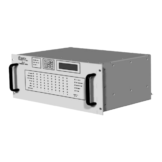
Description of CRS-300 Features 1.3.1 Front Panel Figure 1-3 shows the CRS-300 Front Panel features, and the manual chapter sections where you may reference additional information about that feature. The CRS-300 is constructed as a 4RU-high, rack-mounting chassis that can be freestanding, if desired. -
Page 32: Rear Panel
Chapter 5. MODEM, RMI/TMI, SWITCH CONFIGURATION Figure 1-4 shows the back panel of the CRS-300 with an example array of installedTMI cards. Because the RMI can have the capability for several TMIs, depending on user requirements the CRS-300 may be able to use several different TMI cards simultaneously. -
Page 33: Plug-In Module (Card) Assemblies
CRS-300 1:10 Redundancy Switch MN/CRS300.IOM Introduction Revision 19 1.3.3 Plug-in Module (Card) Assemblies Chapter 3. SWITCH CONNECTORS PINOUTS 1.3.3.1 CRS-300 System Controller Card Assembly DB-9 Female DB-25 Male Figure 1-5. CRS-230 System Controller (AS/0377) DB-9 Male DB-25 Female 1.3.3.2 Power Supply Card Assemblies Figure 1-6. -
Page 34: Modem Interface Cards
CRS-300 1:10 Redundancy Switch MN/CRS300.IOM Introduction Revision 19 1.3.3.3 Modem Interface Cards 1.3.3.3.1 CDM-625/A, CDM-570/A, CDM-570L/AL, CDM-600/L Interface Cards The following tables indicate which TMI (Traffic Modem Interface) cards and which RMI (Redundant Modem Interface) cards should be used with each modem and data type:... -
Page 35: Rmi Card
CRS-300 1:10 Redundancy Switch MN/CRS300.IOM Introduction Revision 19 1.3.3.3.1.1 RMI Card (2X) BNC - Male DB-15 Male Figure 1-8. CRS-310 RMI (PL/9579-1) HD-50 Female DB-25 Male 1.3.3.3.1.2 TMI Cards Figure 1-9. CRS-320 TMI EIA-232/-422 (PL/9581-1) OBSOLETE REPLACED BY CRS-340 DB-25 Female... -
Page 36: Cards
CRS-300 1:10 Redundancy Switch MN/CRS300.IOM Introduction Revision 19 Figure 1-13. CRS-370 TMI HSSI (PL/9034-1) FOR USE WITH CDM-600/L ONLY HD-50 Female DB-25 Male Depending on the traffic data type, the appropriate jumper settings are provided on the TMI to ensure proper operation for RTS/CTS, DTR/DSR (CRS-320 (obsolete) or CRS-340 TMIs) and CA/TA (CRS-370 TMI). -
Page 37: Rmi Cards
CRS-300 1:10 Redundancy Switch MN/CRS300.IOM Introduction Revision 19 Notes (as of April 2007): 1) Use CRS-316 instead of CRS-315. To maintain older TMIs in the field, Switch firmware must also support the CRS-315. 2) Use CRS-336 instead of CRS-335. To maintain older TMIs in the field, Switch firmware must also support the CRS-335. -
Page 38: Tmi Cards
CRS-300 1:10 Redundancy Switch MN/CRS300.IOM Introduction Revision 19 1.3.3.3.2.2 TMI Cards DB-25 Female Figure 1-17. CRS-315 TMI (PL/11493-1) OBSOLETE DB-25 Male HD-15 Female DB-25 Female RJ-45 Figure 1-18. CRS-316 TMI RS422 GigE (PL/12498-1) ALSO USED WITH CDM-625/A DB-25 Male RJ-45... -
Page 39: Optional Crs-350 Esc Switch
CRS-300 1:10 Redundancy Switch MN/CRS300.IOM Introduction Revision 19 (8X) BNC Male HD-15 Female Figure 1-22. CRS-345 TMI G.703 (4 ports) (PL/11495-1) FOR USE WITH CDM-700 ONLY DB-9 Makle (4X) RJ-45 Figure 1-23. CRS-365 TMI E1 (1-4 ports) (PL/12985-1) FOR USE WITH... -
Page 40: Figure 1-25. Crs-355 Udi
CRS-300 1:10 Redundancy Switch MN/CRS300.IOM Introduction Revision 19 Figure 1-25 shows the user interface for one of the (10) CRS-355 UDIs that plug in at the front panel of the CRS-350 ESC Switch. As explained in detail in the pertinent modem sections of Chapter 4. -
Page 41: Summary Of Specifications
Switch to Redundant Modem following a Unit fault, Tx or Rx traffic faults Switching Time 9 seconds max. (Delay interval set to minimum, 1 sec) • CRS-300 without CRS-280/280L IF Switch: IF ON / OFF control through the IF Switching Switch controller. •... -
Page 42: Modem Vs. Terrestrial User Data Interface Specifications
CRS-300 1:10 Redundancy Switch MN/CRS300.IOM Introduction Revision 19 1.5.2 Modem vs. Terrestrial User Data Interface Specifications Modem User Data Type User Data Connector(s) EIA-422, V.35 (1) DB-25F CRS-316 Single-port Ethernet Bridge Mode (1) RJ45 (2) BNCs CRS-325 G.703 Bal (DDI,IDO, DDO, IDI) (1) DB-15F G.703 Unbal (DDI, IDO) -
Page 43: And Crs-280L If Switch Specifications
CRS-300 1:10 Redundancy Switch MN/CRS300.IOM Introduction Revision 19 1.5.3 CRS-280 and CRS-280L IF Switch Specifications Requirement Characteristic CRS-280 (70/140MHz) CRS-280L (L-Band) Tx/Rx Operating Freq 50 to 180 MHz 950 to 1950 MHz Tx / Rx Connectors BNC female N-Type female (50Ω) 18 dB return loss into 75Ω... -
Page 44: Dimensional Envelope Details
CRS-300 1:10 Redundancy Switch MN/CRS300.IOM Introduction Revision 19 1.5.5 Dimensional Envelopes Details Figure 1-27. CRS-300 1:1 Redundancy Switch 1–20... -
Page 45: Figure 1-28. Crs-280 (70/140 Mhz) If Switch
CRS-300 1:10 Redundancy Switch MN/CRS300.IOM Introduction Revision 19 Figure 1-28. CRS-280 (70/140 MHz) IF Switch 1–21... -
Page 46: Figure 1-29. Crs-280L (L-Band) If Switch
CRS-300 1:10 Redundancy Switch MN/CRS300.IOM Introduction Revision 19 17.00 (43.18) 13.92 (35.36) 13.18 (33.48) 6.96 (17.68) 19.00 (48.26) Figure 1-29. CRS-280L (L-Band) IF Switch 1–22... -
Page 47: Figure 1-30. Crs-350 Esc Switch
CRS-300 1:10 Redundancy Switch MN/CRS300.IOM Introduction Revision 19 Figure 1-30. CRS-350 ESC Switch 1–23... - Page 48 CRS-300 1:10 Redundancy Switch MN/CRS300.IOM Introduction Revision 19 Notes: 1–24...
-
Page 49: Chapter 2. Installation
Unpack and Inspect the Shipment Figure 2-1. Unpacking and Inspecting the Shipment The CRS-300 1:10 Redundancy Switch, its optional Installation and Operation Manual (otherwise available online at http://www.comtechefdata.com), and its power cords were packaged and shipped in a reusable cardboard carton containing protective foam spacing. -
Page 50: Install The Unit Into A Rack Enclosure
Figure 2-2 provides a “cut-away” side view of a typical rack configuration for modems combined with the CRS-300, optional CRS-280, and optional CRS-350: • The CRS-300 is constructed as a 4RU-high, rack-mounting chassis. Handles on the Switch front panel facilitate placement and removal of the Switch into a rack. •... - Page 51 CANNOT have rack slides mounted to the sides of the chassis – air flow must not be impeded. Comtech EF Data recommends that an alternate method of support is provided within the rack, such as standard rack shelves, as needed.
-
Page 52: Figure 2-2. Typical Rack Mounting Configuration
CRS-300 1:10 Redundancy Switch MN/CRS300.IOM Installation Revision 19 Feature Description Custom Rack Enclosure (side view) Standard Rack Shelving Rack Enclosure Threaded Mounting Rail (typical) Product Front Panel (typical) User-supplied Screws CRS-300 1:10 Redundancy Switch Redundant Modem 1 to 10 Traffic Modems... -
Page 53: Cabling Connection Types
3.1.1 Coaxial Cable Connections Figure 3-1 show the coaxial cables (plugs) and their mating connectors (jacks/sockets) that Comtech EF Data uses with their products: ‘BNC’, ‘TNC’, ‘N’, ‘F’, and ‘SMA’. Connector Type Coupling Type Plug (Male) -
Page 54: Type 'Bnc
CRS-300 1:10 Redundancy Switch MN/CRS300.IOM Switch Connectors and Pinouts Revision 19 These connectors are available in two coupling styles: Bayonet or Threaded: • Bayonet Coupling Style – The jack has a pair of guideposts that accommodate the plug’s lockdown slots. This lockdown design provides secure assembly without over-tightening the connection. -
Page 55: Type 'Sma' (Subminiature Version 'A')
CRS-300 1:10 Redundancy Switch MN/CRS300.IOM Switch Connectors and Pinouts Revision 19 3.1.1.5 Type ‘SMA’ (Subminiature Version ‘A’) Type ‘SMA’ connectors feature a Threaded Coupling design similar to Type ‘TNC’, Type ‘N’, and Type ‘F’ connectors. 3.1.2 D-Subminiature Cable Connections Type ‘D’ Connection Type... -
Page 56: User Data Connectors
The CRS-280/350 performs the same bridging and backing up functions of the Tx and Rx IF signals identically to how the CRS-300 processes the terrestrial data signals. 3.2.1.2... -
Page 57: Remote Control Connector, Db-9M
CRS-300 1:10 Redundancy Switch MN/CRS300.IOM Switch Connectors and Pinouts Revision 19 3.2.1.3 Remote Control Connector, DB-9M The DB-9M Remote Control connector on the CRS-230 provides 2-Wire EIA-232 and EIA-485 serial remote monitor and control access to the Switch. Table 3-2. Remote Control Connector... -
Page 58: System Alarms Connector, Db-25F
CRS-300 1:10 Redundancy Switch MN/CRS300.IOM Switch Connectors and Pinouts Revision 19 3.2.1.4 System Alarms Connector, DB-25F See Table 3-3 for the pinouts for the DB-25F “System Alarms” connector on the CRS-230. Table 3-3. System Alarms Connector Signal Function by Mode of Operation “Show Fault”... -
Page 59: Tmi User Data Connectors
CRS-300 1:10 Redundancy Switch MN/CRS300.IOM Switch Connectors and Pinouts Revision 19 3.2.2 TMI User Data Connectors 3.2.2.1 EIA-232/422/V.35 Connector, DB-25F (CRS-316) See Table 3-4 for the pinouts of the DB-25F EIA-232/422/V.35 User Data Interface connector – “J2” on the CRS-316 TMI. -
Page 60: Eia-232/422/V.35/Lvds Connector, Db-25F (Crs-320/340)
CRS-300 1:10 Redundancy Switch MN/CRS300.IOM Switch Connectors and Pinouts Revision 19 3.2.2.2 EIA-232/422/V.35/LVDS Connector, DB-25F (CRS-320/340) Table 3-5 indicates the pinout for the DB-25F EIA-232/422/V.35/LVDS User Data Interface connector – “J1” on the CRS-320 TMI (obsolete), and “J2” on the CRS-340 TMI. -
Page 61: Asi Connectors, Bnc (Crs-325)
CRS-300 1:10 Redundancy Switch MN/CRS300.IOM Switch Connectors and Pinouts Revision 19 3.2.2.3 ASI Connectors, BNC (CRS-325) These BNC female connectors provide the Actuator Sensor Interface (ASI) User Data Interface on the CRS-325 TMI. Table 3-6. ASI Connectors BNC Connector TMI CRS-325 Ref Des... -
Page 62: Balanced G.703 Connector, Db-15F (Crs-325/330/340)
CRS-300 1:10 Redundancy Switch MN/CRS300.IOM Switch Connectors and Pinouts Revision 19 3.2.2.5 Balanced G.703 Connector, DB-15F (CRS-325/330/340) See Table 3-8 for the pinout for the DB-15F Balanced G.703 User Data Interface connectors – “J6” on the CRS-325 TMI; “J1” on the CRS-330 TMI; and “J2” on the CRS-340 TMI. -
Page 63: Unbalanced G.703 Connectors, Bnc (Crs-325/330/340)
CRS-300 1:10 Redundancy Switch MN/CRS300.IOM Switch Connectors and Pinouts Revision 19 3.2.2.6 Unbalanced G.703 Connectors, BNC (CRS-325/330/340) These BNC female connectors provide the Unbalanced G.703 User Data Interface on the CRS-325, CRS-330, and CRS-340 TMIs. Table 3-9. Unbalanced G.703 Connectors... -
Page 64: Hssi Connector, Hd-50F (Crs-336/370)
CRS-300 1:10 Redundancy Switch MN/CRS300.IOM Switch Connectors and Pinouts Revision 19 3.2.2.8 HSSI Connector, HD-50F (CRS-336/370) See Table 3-11 for the pinouts for the HD-50F SCSI-II (HSSI) User Data Interface connectors – “J2” on the CRS-336 TMI, and “J1” on the CRS-370 TMI. -
Page 65: 10/100/1000 Gigabit Ethernet Connector, Rj-45F (Crs-316/336)
CRS-300 1:10 Redundancy Switch MN/CRS300.IOM Switch Connectors and Pinouts Revision 19 3.2.2.9 10/100/1000 Gigabit Ethernet Connector, RJ-45F (CRS-316/336) See Table 3-12 for the RJ-45F connector pinouts for the 10/100/1000 Gigabit Ethernet User Data Interface (used for Ethernet Bridge Mode) connector – “J4” on the CRS-316 and CRS-336 TMIs. -
Page 66: Quad E1 Connectors, Rj-48F (Crs-365)
CRS-300 1:10 Redundancy Switch MN/CRS300.IOM Switch Connectors and Pinouts Revision 19 3.2.2.10 Quad E1 Connectors, RJ-48F (CRS-365) See Table 3-13 for the RJ-48F connector pinouts for the Quad E1 User Data Interface – Ports 1 through 4 on the CRS-365 TMI. -
Page 67: Quad E1 Connectors, Db-9F (Crs-365D)
CRS-300 1:10 Redundancy Switch MN/CRS300.IOM Switch Connectors and Pinouts Revision 19 3.2.2.11 Quad E1 Connectors, DB-9F (CRS-365D) See Table 3-14 for the DB-9F connector pinouts for the Quad E1 User Data Interface connectors – “J2” and “J3” on the CRS-365D TMI. -
Page 68: Chassis Ground And Power Connections
PROTECTIVE EARTH AND THAT YOU MUST MAINTAIN THE EQUIPMENT’S CONNECTION TO THE PROTECTIVE EARTH AT ALL TIMES. THE CRS-300 IS DESIGNED FOR CONNECTION TO A POWER SYSTEM THAT HAS SEPARATE GROUND, LINE, AND NEUTRAL CONDUCTORS. THE EQUIPMENT IS NOT DESIGNED FOR CONNECTION TO A POWER SYSTEM THAT HAS NO DIRECT CONNECTION TO GROUND. -
Page 69: Figure 3-4. Crs-300 Chassis Power Supply Interfaces
Switch Connectors and Pinouts Revision 19 3.3.2 Chassis Power Interfaces (TOP) CRS-240 (AC) Power Supply Module (BOTTOM) CRS-250 DC Power Supply Module Figure 3-4. CRS-300 Chassis Power Supply Interfaces 3.3.2.1 Alternating Current (AC) Power Interface Feature Description On / Off Switch... -
Page 70: Figure 3-6. Apply Ac Power
3.3.2.1.1 AC Operation – Power Application Figure 3-6. Apply AC Power Apply AC power to the CRS-300 (Figure 3-6, typical for each module). Do these steps: • First, plug the provided AC power cord female end into the unit. •... -
Page 71: Direct Current (Dc) Power Interface
While this interface features a fuse holder that is press-fit into the body of the IEC Fuse Protection power module, the CRS-300 chassis features an internal electronic resettable fuse. Figure 3-8. Chassis DC Power Interface (CRS-250 DC Power Supply Module) 3.3.2.2.1... - Page 72 CRS-300 1:10 Redundancy Switch MN/CRS300.IOM Switch Connectors and Pinouts Revision 19 Notes: 3–20...
-
Page 73: Chapter 4. Cables And Connections
CRS-300 Front Panel, as instructed in Sect. 5.5. Switch Configuration in this chapter. All cables required for the connection of control, IF, and traffic data between the CRS-300 1:10 Redundancy Switch and the modems, or within the system, are available from Comtech EF Data. - Page 74 Switch RMI or TMI plug-in card accept the female end of the cable in the section of the module labeled “Modem Interface.” See the subsections in Sect. 1.4 Description of CRS-300 Features for detailed information on these interfaces.
-
Page 75: Switch-To-Switch Connections
CRS-300 1:10 Redundancy Switch MN/CRS300.IOM Cables and Connections Revision 19 4.2 Switch-to-Switch Connections • CRS-300 to CRS-280/280L Connection • CRS-300 to CRS-350 Connection • CRS-300 to CRS-350 to CRS-280/280L Connection 4–3... -
Page 76: To Crs-350 And Crs-280/280L Connection
Revision 19 Switch-to-Switch Connections If your redundancy system requires the Comtech EF Data CRS-280 (70/140 MHz) IF, CRS-280L (L-Band) IF, and/or CRS-350 Engineering Service Channel (ESC) Switch (for use only with the CDM-600/L, CDM-625/A, or SLM-5650/5650A modems), you need to use Control/Data Cable CA/WR0066 to connect the Switches. -
Page 77: Figure 4-1. Control Cable Connection Example For Crs-300 To Crs-280
CRS-300 1:10 Redundancy Switch MN/CRS300.IOM Cables and Connections Revision 19 Figure 4-1. Control Cable Connection Example for CRS-300 to CRS-280 4–5... -
Page 78: Figure 4-2. Control Cable Connection Example For Crs-300 To Crs-280L
CRS-300 1:10 Redundancy Switch MN/CRS300.IOM Cables and Connections Revision 19 Figure 4-2. Control Cable Connection Example for CRS-300 to CRS-280L 4–6... -
Page 79: Figure 4-3. Control Cable Connection Example For Crs-300 To Crs-350
CRS-300 1:10 Redundancy Switch MN/CRS300.IOM Cables and Connections Revision 19 Figure 4-3. Control Cable Connection Example for CRS-300 to CRS-350 4–7... -
Page 80: Figure 4-4. Control Cable Connection Example For Crs-300 To Crs-350 To Crs-280
CRS-300 1:10 Redundancy Switch MN/CRS300.IOM Cables and Connections Revision 19 Figure 4-4. Control Cable Connection Example for CRS-300 to CRS-350 to CRS-280 4–8... -
Page 81: Figure 4-5. Control Cable Connection Example For Crs-300 To Crs-350 To Crs-280L
CRS-300 1:10 Redundancy Switch MN/CRS300.IOM Cables and Connections Revision 19 Figure 4-5. Control Cable Connection Example for CRS-300 to CRS-350 to CRS-280L 4–9... - Page 82 CRS-300 1:10 Redundancy Switch MN/CRS300.IOM Cables and Connections Revision 19 Notes: 4–10...
-
Page 83: If Cable Connections
CRS-300 1:10 Redundancy Switch MN/CRS300.IOM Cables and Connections Revision 19 IF Cable Connections • Single Transponder IF Connections Multiple Transponder IF Connections (Using IF Switch) • 4–11... -
Page 84: If Cable Connections - Single Transponder (Without Crs-280/280L)
CRS-300 1:10 Redundancy Switch MN/CRS300.IOM Cables and Connections Revision 19 IF Cable Connections There are two different possible IF configurations: 1) Single Transponder – All modems are connected to the same user-provided Up/Downconverter. 2) Multiple Transponders – The modems may be grouped and connected in various combinations to multiple Up/Downconverters. -
Page 85: Figure 4-6. If Cabling Example – Single Transponder Configuration
CRS-300 1:10 Redundancy Switch MN/CRS300.IOM Cables and Connections Revision 19 Figure 4-6. IF Cabling Example – Single Transponder Configuration (Without CRS-280/280L – Connections shown for 1:N <1> RM with TMs 3 and 8 only) 4–13... -
Page 86: If Cable Connections - Multiple Transponder (Using If Switch)
CRS-300 1:10 Redundancy Switch MN/CRS300.IOM Cables and Connections Revision 19 4.3.2 IF Cable Connections – Multiple Transponder (Using IF Switch) The CRS-280 IF (70/140 MHz) Switch provides complete isolation of the IF signals. The Redundant Modem’s IF signals are routed to the Traffic Modem’s IF path when the Switch RMI is online. -
Page 87: Figure 4-7. If Cabling Example – Multiple Transponder Configuration
CRS-300 1:10 Redundancy Switch MN/CRS300.IOM Cables and Connections Revision 19 Figure 4-7. IF Cabling Example – Multiple Transponder Configuration (CRS-280 and CDM-600s shown, connections for RMI and TMI 1 only) 4–15... - Page 88 CRS-300 1:10 Redundancy Switch MN/CRS300.IOM Cables and Connections Revision 19 Notes: 4–16...
-
Page 89: Cdm-625/A Modem Connections
ESC Data Connections – CRS-350 to User o Using the CDM-625/A Modem in CDM-600 Emulator Mode • Preparing the CDM-625/A for Operation in CDM-600/L Emulation Mode o Control and Data Connections – CRS-300 to Modems in CDM-600/L Emulation Mode 4–17... - Page 90 CRS-300 1:10 Redundancy Switch uses the CRS-310 Redundant Modem Interface (RMI) for all driving traffic configurations. When you use the CDM-625/A in a CRS-300 1:10 Redundancy System, you may mix TMIs within the same Switch, with some limitations: For example, while you may use the “P2” (DB-15M) connector on the CRS-310 RMI for Balanced / Unbalanced G.703 or Quad E1 traffic, you may use...
-
Page 91: Carrier-In-Carrier ® (Cnc) Data Connections
® 4.4.2 Carrier-in-Carrier (CnC) Data Connections The CA-0000275 cable bypasses the CRS-300 1:10 Redundancy Switch. ® If you use Carrier-in-Carrier (CnC) with any Traffic CDM-625/A, see Figure 4-8 and do these steps to connect and secure the PMSI Multi-drop CnC Plus Cable CA-0000275 (<11X> DB-9M, 8.25’) between the Redundant CDM-625/A and any CnC-enabled Traffic CDM-625/A(s):... -
Page 92: Figure 4-8. Cdm-625/A To Cdm-625/A Cnc ® Cable Connection Example
CRS-300 1:10 Redundancy Switch MN/CRS300.IOM Cables and Connections Revision 19 ® Figure 4-8. CDM-625/A to CDM-625/A CnC Cable Connection Example (Connections shown for Redundant Modem and Traffic Modems 1, 2, and 3 only) 4–20... -
Page 93: Control And Data Connections - Crs-300 To Modem
Cables and Connections Revision 19 4.4.3 Control and Data Connections – CRS-300 to Modem Table 4-1 shows the TMI and applicable data and control cables that you will need for each of the various data types. Table 4-1. CDM-625/A Cable Usage (RMI/TMI) CDM-625/A Cable Usage (see Appendix B. -
Page 94: Balanced / Unbalanced Data Connections
CRS-300 1:10 Redundancy Switch MN/CRS300.IOM Cables and Connections Revision 19 CA/WR0066 cable as: a control cable between the Traffic CDM-625/A(s) and the CRS-330 or CRS-340 TMI; as a data cable with the CRS-316 TMI; and as a combination control/data cable for use with the CRS-340 TMI. -
Page 95: Quad E1 Data Connections
CRS-300 1:10 Redundancy Switch MN/CRS300.IOM Cables and Connections Revision 19 First, do these steps to connect the Control/Data Cable CA/WR0066 (for control purposes) between the Redundant CDM-625/A and the Switch RMI (see Sect. 4.4.3.1). Next, do these steps to connect and secure the Data Cable CA-0000072 (DB-15F to DB-9M, 6’), between the Redundant CDM-625/A and Switch RMI:... -
Page 96: Asi Data Connections
CRS-300 1:10 Redundancy Switch MN/CRS300.IOM Cables and Connections Revision 19 • DB-9F connector labeled “Balanced G.703” on the Redundant CDM-625/A (using “P3” connector on cable), –and– • DB-9F connector labeled “Aux G.703” on the Redundant CDM-625/A (using “P2” connector on cable). -
Page 97: Data Connections
CRS-300 1:10 Redundancy Switch MN/CRS300.IOM Cables and Connections Revision 19 • BNC connector labeled “J3 Tx” on the Switch TMI(s), to BNC connector labeled “Unbal G.703/ASI – IN” on the Traffic CDM-625/A(s), and • BNC connector labeled “J5 Rx”on the Switch TMI(s) to BNC connector labeled “Unbal G.703/ASI –... -
Page 98: Hssi Data Connections
CRS-300 1:10 Redundancy Switch MN/CRS300.IOM Cables and Connections Revision 19 4.4.3.6 HSSI Data Connections If HSSI is the driving traffic data type (see Figure 4-9 and Figure 4-10): First, connect the Control/Data Cable CA/WR0066 (for control/data purposes) between the Redundant CDM-625/A and the Switch RMI (see Sect. 4.4.3.1). -
Page 99: Ethernet Data Connection - Wired-Thru Method (No Sub-Mux)
CRS-300 1:10 Redundancy Switch MN/CRS300.IOM Cables and Connections Revision 19 3) When you use Ethernet in combination with other data interfaces in the redundancy system – i.e., an IP Sub-Mux configuration – you must use the wired-around method, explained in Sect 4.4.3.8.2, to make all cabling connections. -
Page 100: Ethernet Data Connection - Wired-Around Method (Sub-Mux)
CRS-300 1:10 Redundancy Switch MN/CRS300.IOM Cables and Connections Revision 19 3) You may use the CRS-336 for single-port Ethernet Bridge Mode or HSSI, but not both at the same time. The CRS-336 does not handle Sub-Mux operation (where the CDM-625/A may use Ethernet Bridge Mode and EIA-530 simultaneously). -
Page 101: Figure 4-9. Crs-300 To Cdm-625/A Cable Connection Example – G.703-Driven Configuration
CRS-300 1:10 Redundancy Switch MN/CRS300.IOM Cables and Connections Revision 19 Figure 4-9. CRS-300 to CDM-625/A Cable Connection Example – G.703-driven Configuration (Connections shown for RMI and TMIs 1, 3, 5, 7, and 9 only) 4–29... -
Page 102: Figure 4-10. Crs-300 To Cdm-625/A Cable Connection Example – G.703-Driven Configuration
CRS-300 1:10 Redundancy Switch MN/CRS300.IOM Cables and Connections Revision 19 Figure 4-10. CRS-300 to CDM-625/A Cable Connection Example – G.703-driven Configuration (Connections shown for RMI and TMIs 1, 3, 5, 7, and 9 only) 4–30... -
Page 103: Figure 4-11. Crs-300 To Cdm-625/A Cable Connection Example – Quad E1-Driven Configuration
CRS-300 1:10 Redundancy Switch MN/CRS300.IOM Cables and Connections Revision 19 Figure 4-11. CRS-300 to CDM-625/A Cable Connection Example – Quad E1-driven Configuration (Connections shown for RMI and TMIs 1, 3, 5, 7, and 9 only) 4–31... -
Page 104: Figure 4-12. Crs-300 To Cdm-625/A Cable Connection Example – Sub-Mux Tmis 3 & 9
CRS-300 1:10 Redundancy Switch MN/CRS300.IOM Cables and Connections Revision 19 Figure 4-12. CRS-300 to CDM-625/A Cable Connection Example – Sub-Mux TMIs 3 & 9 (Connections shown for RMI and TMIs 1, 3, 5, 7, and 9 only) 4–32... -
Page 105: Data Connections - Crs-300 To User
For Quad E1 operation, the optional CA-0000163 and CA-0000164 Adapter Cables may be purchased from Comtech EF Data to adapt the Balanced G.703 or Auxiliary G.703 9-pin Type ‘D’ female connectors to either a standard 15-pin Type ‘D’ or a RJ-48 female connection pair. See Figure B-30 or Figure B-31 in Appendix B. -
Page 106: Preparing The Cdm-625/A For Operation In Cdm-600/L Emulation Mode
• DB-25F connector labeled “Data Interface” on the CDM-625/A. See Sect. 4.4.3 Control and Data Connections – CRS-300 to Modems for the system configuration and cable interconnection details for the various traffic data types that are available in this operational mode. - Page 107 CRS-300 1:10 Redundancy Switch MN/CRS300.IOM Cables and Connections Revision 19 Figure 4-13. Cabling Example for CRS-350 to CDM-625/A (Connections shown for RMI and TMI 1 only) 4–35...
-
Page 108: Figure 4-14. Data Cables – Crs-300 To Cdm-625/A (Cdm-600/L Emulation Mode)
CRS-300 1:10 Redundancy Switch MN/CRS300.IOM Cables and Connections Revision 19 Figure 4-14. Data Cables – CRS-300 to CDM-625/A (CDM-600/L Emulation Mode) (Connections shown for RMI and TMIs 1, 3, 5, and 7 only) 4–36... -
Page 109: Cdm-570/A, Cdm-570L/Al Modem Connections
CRS-300 1:10 Redundancy Switch MN/CRS300.IOM Cables and Connections Revision 19 CDM-570/A, CDM-570L/AL Modem Connections • Control and Data Connections – CRS-300 to Modems • User Data Connections – CRS-300 to User 4–37... -
Page 110: Control And Data Connections - Crs-300 To Modems
Traffic modems with differing data types can all be supported by the Redundant Modem. 4.5.1 Control and Data Connections – CRS-300 to Modems The 25-pin Control/Data Cable CA/WR0066 provides the EIA-422/232 traffic data path and serial communication path between the Switch and the modems. Therefore, you must alwys use this cable, even when the data type is G.703. -
Page 111: Figure 4-15. Data Cable Connection Example – Crs-300 To Cdm-570/A Or Cdm-570L/Al
For T1/E1 operation, the optional CN-0000268 T1/E1 Adapter (see Figure B-32 in Appendix B. CABLE DRAWINGS) may be purchased from Comtech EF Data to adapt the Balanced G.703 DB-15F connector on the User Data side of the Switch TMI to a RJ-48 female connection. - Page 112 CRS-300 1:10 Redundancy Switch MN/CRS300.IOM Cables and Connections Revision 19 Notes: 4–40...
-
Page 113: Slm-5650/5650A Modem Connections
• Control Cable Connections – CRS-300 to Modems • Traffic Data Connections – CRS-300 to Modems • Ethernet Traffic Data Connections – CRS-300 to Modems • User Data Connections – CRS-300 to User • ESC Data Connections – CRS-350 to Modems •... -
Page 114: Rmi/Tmi Limitations And Considerations
G.703 or single port Gigabit Ethernet card options. 4.6.2 Control Cable Connections – CRS-300 to Modems The Control Cable CA/WR12136-1 provides the serial communication path between the Switch and the modems and controls the modem’s external Tx IF-mute control line. You must always use this cable. -
Page 115: Traffic Data Connections - Crs-300 To Modems
• HD-15F connector labeled “J9 Auxiliary” on the SLM-5650/5650A. 4.6.3 Traffic Data Connections – CRS-300 to Modems Referring to Figure 4-16: If HSSI is the traffic data type, do these steps to connect and secure the HSSI Data Cable CA/WR9189-6 between the Switch and each SLM-5650/5650A: •... -
Page 116: Ethernet Traffic Data Connections
Network Processor (NP) Interface when operating in Single-port Ethernet Bridge Mode. 4.6.4 User Data Connections – CRS-300 to User You must connect your traffic data from the external router, multiplexing equipment, or test data generator to the connectors on the Switch TMI labeled “User Data Interface”. This interface replaces the direct connection to the Traffic Modem’s “Data Interface”... -
Page 117: User Esc Data Connections - Crs-350 To User
CRS-300 1:10 Redundancy Switch MN/CRS300.IOM Cables and Connections Revision 19 DB-25F Jxx “Overhead” connector on the CRS-350 rear panel (where xx specifies the • numbers 1 through 10 Traffic SLM-5650/5650As, and “R11” is reserved for the Redundant SLM-5650/5650A), to DB-25M “P1 Overhead Data” connector on each SLM-5650/5650A. -
Page 118: Figure 4-16. Control And Data Cables Example #1 – Crs-300 To Slm-5650/5650A
CRS-300 1:10 Redundancy Switch MN/CRS300.IOM Cables and Connections Revision 19 Figure 4-16. Control and Data Cables Example #1 – CRS-300 to SLM-5650/5650A (Connections shown for RMI & TMIs 1, 3, and 8 only) 4–46... -
Page 119: Figure 4-17. Control And Data Cables Example #2 – Crs-300 To Slm-5650/5650A
CRS-300 1:10 Redundancy Switch MN/CRS300.IOM Cables and Connections Revision 19 Figure 4-17. Control and Data Cables Example #2 – CRS-300 to SLM-5650/5650A (Connections shown for RMI & TMIs 4 and 7 only) 4–47... -
Page 120: Figure 4-18. Control And Data Cables Example #3 – Crs-300 To Slm-5650/5650A
CRS-300 1:10 Redundancy Switch MN/CRS300.IOM Cables and Connections Revision 19 Figure 4-18. Control and Data Cables Example #3 – CRS-300 to SLM-5650/5650A (Connections shown for RMI & TMIs 1 and 3 only) 4–48... - Page 121 CRS-300 1:10 Redundancy Switch MN/CRS300.IOM Cables and Connections Revision 19 Figure 4-19. Cabling Example for CRS-350 to SLM-5650/5650A (Connections shown for RMI and TMI 1 only) 4–49...
- Page 122 CRS-300 1:10 Redundancy Switch MN/CRS300.IOM Cables and Connections Revision 19 Notes: 4–50...
-
Page 123: Cdm-Qx/Qxl Modem Connections
4.7 CDM-Qx/QxL Modem Connections • RMI/TMI Limitations and Considerations • EIA-485 Connections – CRS-300 to Modems • Control Y-Cable Connections – CRS-300 to Modems • Traffic Data Connections – CRS-300 to Modems • User Data Connections – CRS-300 to User... - Page 124 There are two types of EIA-485 Multi-drop cable available: a standard CA/WR11417-1 shielded cable to guard against EMC (Electromagnetic Compatibility) concerns, or an optional CA/RB11423-1 ribbon cable. Both are available from Comtech EF Data. See Figure 4-20 and do these steps to connect the EIA-485 multi-drop cable between the Switch and the modems: •...
-
Page 125: Figure 4-20. Eia-485 Multi-Drop Cabling Example – Crs-300 To Cdm-Qx/Qxl
CRS-300 1:10 Redundancy Switch MN/CRS300.IOM Cables and Connections Revision 19 Figure 4-20. EIA-485 Multi-drop Cabling Example – CRS-300 to CDM-Qx/QxL (Connections shown for RMI and TMIs 1 and 3 only) 4–53... -
Page 126: Control Y-Cable Connections - Crs-300 To Modems
Cables and Connections Revision 19 4.7.3 Control Y-Cable Connections – CRS-300 to Modems All traffic data configurations require the Control Y-Cable CA/WR12069-1. Do these steps to connect Switch RMI/TMI(s) and each CDM-Qx/QxL: HD-15F connector labeled “J1” on the Switch RMI or TMI(s), to •... -
Page 127: User Data Connections - Crs-300 To User
RJ-48 connectors labeled “Port 1” through “Port 4” on the Traffic CDM-Qx/QxL. • 4.7.5 User Data Connections – CRS-300 to User You must connect your traffic data from the multiplexing equipment or test data generator to the connectors on the Switch TMI labeled “User Data Interface”. This interface replaces the direct connection to the Traffic Modem’s “Data Interface”... - Page 128 CRS-300 1:10 Redundancy Switch MN/CRS300.IOM Cables and Connections Revision 19 Figure 4-21. Control Y-Cables and EIA-530/-232 Data Cables – CRS-300 to CDM-Qx/QxL (Connections shown for RMI and TMI 1 only) 4–56...
- Page 129 CRS-300 1:10 Redundancy Switch MN/CRS300.IOM Cables and Connections Revision 19 Figure 4-22. Control Y-Cables and Balanced G.703 Data Cables – CRS-300 to CDM- Qx/QxL (Connections shown for RMI and TMI 1 only) 4–57...
- Page 130 CRS-300 1:10 Redundancy Switch MN/CRS300.IOM Cables and Connections Revision 19 Figure 4-23. Control Y-Cables and Unbalanced G.703 Data Cables – CRS-300 to CDM- Qx/QxL (Connections shown for RMI and TMI 1 only) 4–58...
-
Page 131: Figure 4-24. Control Cables And Hssi Data Cables – Crs-300 To Cdm-Qx/Qxl
CRS-300 1:10 Redundancy Switch MN/CRS300.IOM Cables and Connections Revision 19 Figure 4-24. Control Cables and HSSI Data Cables – CRS-300 to CDM-Qx/QxL (Connections shown for RMI and TMI 1 only) 4–59... -
Page 132: Figure 4-25. Control Cables And Quad E1 Data Cables – Crs-300 To Cdm-Qx/Qxl
CRS-300 1:10 Redundancy Switch MN/CRS300.IOM Cables and Connections Revision 19 Figure 4-25. Control Cables and Quad E1 Data Cables – CRS-300 to CDM-Qx/QxL (Connections shown for RMI and TMI 1 only) 4–60... -
Page 133: Cdm-710G/710Gl Modem Connections
• RMI/TMI Limitations and Considerations • Interface Combinations • Control Cable Connections – CRS-300 to Modems • Serial Traffic Data Connections – CRS-300 to Modems • Ethernet Traffic Data Connections – CRS-300 to Modems • User Data Connections – CRS-300 to Users... -
Page 134: Cdm-710G/710Gl Modem Connections
CRS-300 1:10 Redundancy Switch MN/CRS300.IOM Cables and Connections Revision 19 CDM-710G/710GL Modem Connections If adding a modem to an operating 1:N system, care needs to be taken not to interfere with the existing traffic. The cabling, power-up sequence and communication connections must be correct to avoid contention in the system from the modem Tx carrier. -
Page 135: Control Cable Connections - Crs-300 To Modems
DB-15M connector labeled “P1 Alarms” on the CDM-710G/710GL. 4.8.4 Serial Traffic Data Connections – CRS-300 to Modems If G.703 is the traffic data type, see Figure 4-26 and do these steps to connect and secure the pair of BNC PL/0813-8 cables between the Switch and each CDM-710G/710GL: •... -
Page 136: User Data Connections – Crs-300 To User
User Data Interface. See Sect. 1.4.3.3 Modem Interface Cards for detailed information on the Switch RMI and TMI cards available for use with the CDM-710G/710GL modems. Figure 4-26. Control and Data Cables Example #1 – CRS-300 to CDM-710G/710GL (Connections shown for RMI & TMIs 1 and 3 only) 4–64... -
Page 137: Figure 4-27. Control And Data Cables Example #2 – Crs-300 To Cdm-710G/710Gl
CRS-300 1:10 Redundancy Switch MN/CRS300.IOM Cables and Connections Revision 19 Figure 4-27. Control and Data Cables Example #2 – CRS-300 to CDM-710G/710GL (Connections shown for RMI & TMIs 1 and 3 only) 4–65... - Page 138 CRS-300 1:10 Redundancy Switch MN/CRS300.IOM Cables and Connections Revision 19 Notes: 4–66...
- Page 139 • RMI/TMI Limitations and Considerations • Interface Combinations • Control Cable Connections – CRS-300 to Modems • Serial Traffic Data Connections – CRS-300 to Modems • Ethernet Traffic Data Connections – CRS-300 to Modems • User Data Connections – CRS-300 to Users...
-
Page 140: Table 4-3. Cdm-710 Interface Card Combinations
CRS-300 1:10 Redundancy Switch MN/CRS300.IOM Cables and Connections Revision 19 CDM-710 Modem Connections When adding a modem to an operating 1:N system, you must take care not to interfere with the existing traffic. The cabling, power-up sequence, and communication connections must be correct to avoid contention in the system from the modem Tx carrier. -
Page 141: Ethernet Traffic Data Connections - Crs-300 To Modems
• 4.9.4 Serial Traffic Data Connections – CRS-300 to Modems If ASI is the traffic data type, see Figure 4-28 and do these steps to connect and secure the pair of BNC PL/0813-8 cables between the Switch and each CDM-710: BNC connectors labeled “J4 Tx”... -
Page 142: User Data Connections – Crs-300 To User
User Data Interface. See Sect. 1.4.3.3 Modem Interface Cards for detailed information on the Switch RMI and TMI cards available for use with the CDM-710 modems. Figure 4-28. Control and Data Cables Example #1 – CRS-300 to CDM-710 (Connections shown for RMI & TMIs 1 and 3 only) -
Page 143: Figure 4-29. Control And Data Cables Example #2 – Crs-300 To Cdm-710
CRS-300 1:10 Redundancy Switch MN/CRS300.IOM Cables and Connections Revision 19 Figure 4-29. Control and Data Cables Example #2 – CRS-300 to CDM-710 (Connections shown for RMI & TMIs 1 and 3 only) 4–71... - Page 144 CRS-300 1:10 Redundancy Switch MN/CRS300.IOM Cables and Connections Revision 19 Notes: 4–72...
- Page 145 • RMI/TMI Limitations and Considerations • Interface Combinations • Control Cable Connections – CRS-300 to Modems • Serial Traffic Data Connections – CRS-300 to Modems • Ethernet Traffic Data Connections – CRS-300 to Modems • Wired-thru Connections • Wired-around Connections •...
-
Page 146: Table 4-4. Cdm-700 Interface Card Combinations
CRS-300 1:10 Redundancy Switch MN/CRS300.IOM Cables and Connections Revision 19 4.10 CDM-700 Modem Connections If adding a modem to an operating 1:N system, care needs to be taken not to interfere with the existing traffic. The cabling, power-up sequence and communication connections must be correct to avoid contention in the system from the modem Tx carrier. -
Page 147: Control Cable Connections – Crs-300 To Modems
DB-15M connector labeled “P1 Alarms” on the CDM-700. • 4.10.4 Serial Traffic Data Connections – CRS-300 to Modems If G.703 is the traffic data type, see Figure 4-30, Figure 4-31, Figure 4-33, or Figure 4-35 and do these steps to connect and secure the Traffic Data Cables CA/RF12278-1 and CA/RF12279-1... -
Page 148: Wired-Thru Connections
• connectors labeled "Rx" on the CDM-700's CDI-50 plug-in module. 4.10.5 Ethernet Traffic Data Connections – CRS-300 to Modems You have two choices for handling Ethernet traffic data: If the Traffic Modem uses Ethernet as the sole traffic data type, then you must route the •... -
Page 149: User Data Connections - Crs-300 To User
RJ-45 connector on the user-provided Ethernet switch • 4.10.6 User Data Connections – CRS-300 to User You must connect your traffic data from the external router, multiplexing equipment, or test data generator to the connectors on the Switch TMI labeled “User Data Interface”. This interface replaces the direct connection to the Traffic CDM-700’s “Data Interface”... -
Page 150: Figure 4-30. Control And Traffic Data Cables Example #1 – Crs-300 To Cdm-700
CRS-300 1:10 Redundancy Switch MN/CRS300.IOM Cables and Connections Revision 19 Figure 4-30. Control and Traffic Data Cables Example #1 – CRS-300 to CDM-700 (Connections shown for RMI and TMIs 1, 3, and 8 only) 4–78... -
Page 151: Figure 4-31. Control And Traffic Data Cables Example #2 – Crs-300 To Cdm-700
CRS-300 1:10 Redundancy Switch MN/CRS300.IOM Cables and Connections Revision 19 Figure 4-31. Control and Traffic Data Cables Example #2 – CRS-300 to CDM-700 (Connections shown for RMI and TMIs 3 and 8 only) 4–79... -
Page 152: Figure 4-32. Cdm-700 Ip Connections – Wired-Thru Example #1
CRS-300 1:10 Redundancy Switch MN/CRS300.IOM Cables and Connections Revision 19 Figure 4-32. CDM-700 IP Connections – Wired-thru Example #1 (Connections shown for RMI and TMIs 1, 3, and 8 only) 4–80... -
Page 153: Figure 4-33. Cdm-700 Ip Connections – Wired-Thru Example #2
CRS-300 1:10 Redundancy Switch MN/CRS300.IOM Cables and Connections Revision 19 Figure 4-33. CDM-700 IP Connections – Wired-thru Example #2 (Connections shown for RMI and TMIs 1, 3, and 8 only) 4–81... -
Page 154: Figure 4-34. Cdm-700 Ip Connections – Wired-Around Example #1
CRS-300 1:10 Redundancy Switch MN/CRS300.IOM Cables and Connections Revision 19 Figure 4-34. CDM-700 IP Connections – Wired-around Example #1 (Connections shown for RMI and TMIs 1, 3, and 8 only) 4–82... -
Page 155: Figure 4-35. Cdm-700 Ip Connections – Wired-Around Example #2
CRS-300 1:10 Redundancy Switch MN/CRS300.IOM Cables and Connections Revision 19 Figure 4-35. CDM-700 IP Connections – Wired-around Example #2 (Connections shown for RMI and TMIs 1, 3, and 8 only) 4–83... - Page 156 CRS-300 1:10 Redundancy Switch MN/CRS300.IOM Cables and Connections Revision 19 Notes: 4–84...
-
Page 157: Cdm-600/L Modem Connections
Emulator Mode, serve as operationally transparent replacement units for the CDM-600/L Open Network Satellite Modems. • Control and Data Connections – CRS-300 to Modems • User Data Connections – CRS-300 to User • ESC Data Connections – CRS-350 to Modems •... - Page 158 Traffic modems with differing data types can all be supported by the Redundant Modem. 4.11.1 Control and Data Connections – CRS-300 to Modems See Sect. 1.4.3.3 Modem Interface Cards for detailed information on the Switch RMI and TMI cards available for use with the CDM-600/L modems.
-
Page 159: Figure 4-36. Data Cable Connection Example – Crs-300 To Cdm-600/L
CRS-300 1:10 Redundancy Switch MN/CRS300.IOM Cables and Connections Revision 19 Figure 4-36. Data Cable Connection Example – CRS-300 to CDM-600/L (Connections shown for RMI and TMIs 1, 3, 5, and 7 only) 4–87... -
Page 160: User Data Connections - Crs-300 To User
For T1/E1 operation, the optional CN-0000268 T1/E1 Adapter (see Figure B-32 in Appendix B. CABLE DRAWINGS) may be purchased from Comtech EF Data to adapt the Balanced G.703 DB-15F connector on the User Data side of the Switch TMI to a RJ-48 female connection. - Page 161 CRS-300 1:10 Redundancy Switch MN/CRS300.IOM Cables and Connections Revision 19 Figure 4-37. Cabling Example for CRS-350 to CDM-600/L (Connections shown for RMI and TMI 1 only) 4–89...
- Page 162 CRS-300 1:10 Redundancy Switch MN/CRS300.IOM Cables and Connections Revision 19 Notes: 4–90...
- Page 163 Finally, once you properly configure the modems and Switch RMI/TMI cards for 1:N redundant operation, you should then set the Switch for proper operation using the CRS-300 Front Panel, as instructed in this chapter in Sect. 5.5. Configure the CRS-300 Switch.
-
Page 164: Chapter 5. Modem, Rmi/Tmi, And Switch Configuration
All Traffic Modems and the Redundant Modem must be of the same model in order for the CRS-300 1:10 Redundancy Switch to operate correctly. You must also configure the Redundant Modem with the same firmware version and installed options as the Traffic Modems, so that it can properly mimic all installed Traffic Modems in the event of switchover. -
Page 165: Update Your Modem Firmware
5.2.2.1 Update Your Modem Firmware Comtech EF Data ships its products with the latest version of operating firmware. If you need to update your modem firmware, you may download the update from the Comtech EF Data Web site (www.comtechefdata.com). You may also receive the firmware update archive file via e- mail from Comtech EF Data Product Support. -
Page 166: Configure Cdm-625/A 1:N Redundancy For Carrier-In-Carrier
PMSI Multi-drop CnC Plus Cable (<11X> DB-9M, 8.25’) between the Redundant Modem and all other Traffic Modem(s) using CnC. The CA-0000275 cable bypasses the CRS-300 1:10 Redundancy Switch. Once you interconnect all CnC-enabled modems with the PMSI Multi-drop Cable, you must then configure each CnC-enabled modem. -
Page 167: Configure Switch-To-Cdm-570/A, Cdm-570L/Al, Cdm-600/L 1:N Redundancy
CRS-300 1:10 Redundancy Switch MN/CRS300.IOM Modem, RMI/TMI, and Switch Configuration Revision 19 You must repeat this configuration step for every CnC-enabled CDM-625/A within the configured redundancy system. The Pre-Mapped Symbol Interface (PMSI) is an EIA-485 multi-drop bus system where one device transmits, and all other devices on the multi-drop bus are configured to receive. - Page 168 CRS-300 1:10 Redundancy Switch MN/CRS300.IOM Modem, RMI/TMI, and Switch Configuration Revision 19 5.2.4.3.2 Configure Ethernet Bridge Mode via Optional Network Processor (NP) Interface Due to backplane limitations, the Switch supports Single-port Ethernet Bridge Mode only. Ethernet Bridge Mode redundancy, when using SLM-5650/5650A modems equipped with the optional Network Processor (NP) Interface, is provided by a single IP Address scheme.
-
Page 169: Configure Switch-To-Cdm-Qx/Qxl 1:N Redundancy
CRS-300 1:10 Redundancy Switch MN/CRS300.IOM Modem, RMI/TMI, and Switch Configuration Revision 19 See Chapter 5. FRONT PANEL OPERATION in the SLM-5650 or SLM-5650A Installation and Operation Manual for detailed information about using the modem front panel menus. 5.2.4.4 Configure Switch-to-CDM-Qx/QxL 1:N Redundancy The Switch-to-CDM-Qx/QxL redundancy configuration uses an external EIA-485 multi-drop communication cable. - Page 170 CRS-300 1:10 Redundancy Switch MN/CRS300.IOM Modem, RMI/TMI, and Switch Configuration Revision 19 Typical for each modem – use the CDM-Qx/QxL Front Panel menu to configure the COMMS (make sure to press ENT to save your changes). Do these steps: Step Task Use the ◄...
-
Page 171: Figure 5-2. Cdm-Qx/Qxl / Crs-300 Eia-485 Scheme
Modem, RMI/TMI, and Switch Configuration Revision 19 In this example, the EIA-485 offset address does not affect Modem #1, so the offset can be 0001 to 0099 without affecting other Modems’ EIA-485 addresses. Figure 5-2. CDM-Qx/QxL / CRS-300 EIA-485 Scheme 5–9... -
Page 172: Configure Switch-To-Cdm-710G/710Gl, Cdm-710, Cdm-700 1:N Redundancy
CRS-300 1:10 Redundancy Switch MN/CRS300.IOM Modem, RMI/TMI, and Switch Configuration Revision 19 5.2.4.5 Configure Switch-to-CDM-710G/710GL, CDM-710, CDM-700 1:N Redundancy Only the Rev. A modem chassis (i.e., the chassis with a round-buttoned front panel keypad) and later versions of the CDM-710 and CDM-700 offer 1:N Redundancy operation. -
Page 173: Rmi Card Configuration Reference
Comtech EF Data ships all RMI cards pre-configured – they require no user adjustments. Comtech EF Data ships the CRS-305, CRS-306, and CRS-307 RMI cards pre-set for proper operation. Each card shares a common printed circuit board (CEFD P/N PC/11494x); what distinguishes the cards from one another is the configuration of front panel connectors, and configuration of the Jumper “JMP1”... -
Page 174: Tmi Card Configuration Reference
Figure 5-4 shows the CRS-316 TMI (CEFD P/N PL/12498, Rev ‘A’ or later). Figure 5-4. CRS-316 EIA-530 TMI Card (Jumpers Shown Open) Figure 5-5 shows the jumper section of the CRS-316 TMI PCB. Comtech EF Data ships these TMIs pre-set with jumpers “JP1” through “JP6” open. -
Page 175: Table 5-2. Crs-316 "Jp1" Jumper Settings
CRS-300 1:10 Redundancy Switch MN/CRS300.IOM Modem, RMI/TMI, and Switch Configuration Revision 19 Figure 5-5. CRS-316 “JP1” through “JP6” Jumper Detail (As Shipped) Table 5-2. CRS-316 “JP1” Jumper Settings User Interface Jumper “JP1” Jumper Settings Modem Control Signal Settings Detail Pins Jumped CS_B &... -
Page 176: Table 5-3. Crs-316 "Jp2" Jumper Settings
CRS-300 1:10 Redundancy Switch MN/CRS300.IOM Modem, RMI/TMI, and Switch Configuration Revision 19 Table 5-3. CRS-316 “JP2” Jumper Settings User Interface Jumper “JP2” Jumper Settings Modem Control Signal Settings Detail Pins Jumped CS_A/CTS & RS_A/RTS CDM-625/A Not Connected (Note: TMI as shipped) CS_A/CTS &... -
Page 177: Eia-232/-422, V.35 Interfaces Via The Crs-320 And Crs-340 Tmis
Jumpers “JP1” and “JP2” on the CRS-320 (obsolete) and CRS-340 TMI cards set the functionality of the control signals DTR/DSR and RTS/CTS. See Figure 5-6 and Figure 5-7 – Comtech EF Data ships these TMIs pre-set with jumpers “JP1” and “JP2” open. -
Page 178: Table 5-5. Crs-320/Crs-340 Jumper Settings
CRS-300 1:10 Redundancy Switch MN/CRS300.IOM Modem, RMI/TMI, and Switch Configuration Revision 19 Table 5-5 defines the CRS-320 (obsolete) and CRS-340 TMI control signal configuration jumper “JP1” and “JP2” settings: Table 5-5. CRS-320/CRS-340 Jumper Settings Jumper “JP1” Jumper “JP2” Settings Settings... -
Page 179: Hssi Interfaces Via The Crs-336 Tmi
CRS-300 1:10 Redundancy Switch MN/CRS300.IOM Modem, RMI/TMI, and Switch Configuration Revision 19 5.4.3 HSSI Interfaces via the CRS-336 TMI Figure 5-8 and Figure 5-9 show the CRS-336 TMI (CEFD P/N PL/12499, Rev B or later). Comtech EF Data ships these TMIs with jumpers “JP1” and “JP2” pre-set on a per-modem basis: •... -
Page 180: Table 5-6. Crs-336 Jumper "Jp1" Settings
CRS-300 1:10 Redundancy Switch MN/CRS300.IOM Modem, RMI/TMI, and Switch Configuration Revision 19 Figure 5-9. CRS-336 “JP1” and “JP2” Jumper Detail (As Shipped) Table 5-6. CRS-336 Jumper “JP1” Settings User Interface Jumper “JP1” Jumper Settings Modem Control Signal Setting Settings Detail... -
Page 181: Hssi Interface Via The Crs-370 Tmi
Jumper “J2” on the CRS-370 TMI selects the functionality of the control signals CA and TA. See Figure 5-10 – Comtech EF Data ships this TMI pre-set with jumper “J2” open. Figure 5-10. CRS-370 HSSI to LVDS TMI Card (Jumper Shown Open) Table 5-8 defines the CRS-370 TMI control signal configuration Jumper “J2”... -
Page 182: Configure The Crs-300 Switch
ON/OFF switch for that card. Each Switch is shipped with two power supplies. It is recommended that both be used for maximum reliability. If you use only one power supply card, you must use the CRS-300 Front Panel menu to mask the fault for the unused power supply. Do these steps:... -
Page 183: Update The Crs-300 Switch Firmware
Comtech EF Data Web site (www.comtechefdata.com). You may also receive the firmware update archive file via e-mail from Comtech EF Data Product Support. You may perform the firmware update, without opening the CRS-300, by directly connecting a user-supplied Microsoft Windows-based PC to the “Remote Control” connector located on the CRS-230 System Controller Card. -
Page 184: Switch Firmware Update Procedure
Modem, RMI/TMI, and Switch Configuration Revision 19 The firmware download files are available from Comtech EF Data in two archive file formats: *.exe (self extracting) and *.zip (compressed). Some firewalls will not allow the downloading of *.exe files; in this case, download the *.zip file instead. If applicable, one version prior to the current release is also available for download. -
Page 185: Download And Extract The Firmware Update
C. On the Software Downloads page – click Download Flash and Software Update Files. D. On the Flash & Software Update Files page – select the Modem Accessories hyperlink. E. On the Modems product page – select the CRS-300 product hyperlink. Select the appropriate modem-specific firmware EXE or ZIP download hyperlink Refer to the table in Sect. - Page 186 CRS-300 1:10 Redundancy Switch MN/CRS300.IOM Modem, RMI/TMI, and Switch Configuration Revision 19 Step Task Click [Open] to turn over file extraction to the user-supplied Utility Application. Make sure to extract the • (cont.) firmware files to the “temp” folder created earlier.
-
Page 187: Execute The Cccflash Upload Utility Application
Step Task Make sure a User PC serial port is connected to the CRS-300 “Remote Control” connector (located on the CRS- 230 System Controller Card) with a user-provided EIA-232 serial cable. (Cabling details are shown in the CCCFLASH Uploader dialogue box, and provided in Appendix B. CABLE DRAWINGS.) -
Page 188: Verify Each Active Modem Connection
5.6.2.2 Verify Each Active Modem Connection The LEDs are arranged in columns corresponding to each modem, and should accurately reflect the status of each. Use the CRS-300 Front Panel menu to verify the modem connections. Do these steps: Step Task Verify that the Status LED for each modem shows a GREEN light, indicating no faults. -
Page 189: Set The Switch Operation Mode
When you enable AUTO mode, the first active modem that fails is first bridged by the Redundant Modem, and then backed up. Use the CRS-300 Front Panel menu to enable AUTO mode (make sure to press [ENT] to save your changes). Do these steps:... -
Page 190: Set The Backup Holdoff Period
If the CDM-Qx/QxL configuration includes Carrier-in-Carrier this holdoff time should be no less than 8 seconds. Use the CRS-300 Front Panel menu to set the Backup Holdoff Period. Do these steps: Step Task Use the [←][→] keys to select the nested CONFIG: OPTIONS HOLDOFFS menu. -
Page 191: Set The Alarm Masks
CRS-300 1:10 Redundancy Switch MN/CRS300.IOM Modem, RMI/TMI, and Switch Configuration Revision 19 Use the CRS-300 Front Panel menu to set the Restore Holdoff Period. Do these steps: Step Task Use the [←][→] keys to select the nested CONFIG: OPTIONS HOLDOFFS menu. - Page 192 CRS-300 1:10 Redundancy Switch MN/CRS300.IOM Modem, RMI/TMI, and Switch Configuration Revision 19 Notes: 5–30...
-
Page 193: Chapter 6. Front Panel Operation
It shows two lines 6.1.3 (VFD) of 24 characters each. Nested menus show all available options and prompts that guide you in carrying out required actions. Figure 6-1. CRS-300 Front Panel Features 6–1... -
Page 194: Front Panel Led Indicators
6.1.1 Front Panel LED Indicators 6.1.1.1 Switch Status LED Indicators These three front panel LEDs are located adjacent to the keypad. They show the operational status of the CRS-300 1:10 Redundancy Switch. The LEDs function individually as follows: Condition Description... -
Page 195: Modem Status Led Indicators
CRS-300 1:10 Redundancy Switch MN/CRS300.IOM Front Panel Operation Revision 19 6.1.1.2 Modem Status LED Indicators This array of front panel LEDs, located below the Unit Status LED Indicators group, keypad, and VFD, show the operational status for up to 10 Traffic Modems (six LEDs per modem) plus the Redundant Modem (five LEDs). -
Page 196: Front Panel Keypad
Front Panel Operation Revision 19 6.1.2 Front Panel Keypad The CRS-300 front panel keypad contains six individual key switches mounted behind a sealed membrane overlay. The keys have a positive "click" action for tactile feedback. The keypad has an auto-repeat feature: If a key is held down for more than 1 second, the key action repeats automatically at the rate of 15 keystrokes per second. -
Page 197: Front Panel Vacuum Fluorescent Display (Vfd)
CRS-300 1:10 Redundancy Switch MN/CRS300.IOM Front Panel Operation Revision 19 6.1.3 Front Panel Vacuum Fluorescent Display (VFD) The Front Panel Vacuum Fluorescent Display (VFD) is an active display showing two lines of 24 characters each. It produces an adjustable blue light. Compared to a Liquid Crystal Display (LCD), it has greatly superior viewing characteristics and does not suffer problems of viewing angle or contrast. -
Page 198: Menu Structure
6.1.3.2 Menu Structure Figure 6-2 shows the menu structure of the CRS-300. The menu, branches, and applicable submenus are described in detail in the chapter sections that follow. Note also that chapter sections may refer to the old Recommended Standard (RS) designation rather than the new designation of the Electronic Industries Association (EIA). -
Page 199: Front Panel Operation
CRS-300 1:10 Redundancy Switch MN/CRS300.IOM Front Panel Operation Revision 19 Front Panel Operation 6.2.1 SELECT: (Top-Level) Menu SELECT: CONFIG INFO MONITOR STORE/LD UTIL Use the ◄ ► arrow keys to select from the choices shown, and then press [ENT]. The function... -
Page 200: Config: Manual
CRS-300 1:10 Redundancy Switch MN/CRS300.IOM Front Panel Operation Revision 19 front panel. Conversely, when in Remote mode, the unit may be monitored from the front panel, but configuration parameters may only be changed via the remote control bus. 6.2.2.1 CONFIG: MANUAL... -
Page 201: Config: Options
CRS-300 1:10 Redundancy Switch MN/CRS300.IOM Front Panel Operation Revision 19 In MANUAL mode, the STORED EVENT indicator blinks to alert you that the Switch is effectively not in use. The CDM-7XX modems have Faults and Alarms. For these modems, AUTO Switch Mode will react only to modem Faults;... -
Page 202: Config: Options Alarm-Mask
CRS-300 1:10 Redundancy Switch MN/CRS300.IOM Front Panel Operation Revision 19 If the CDM-Qx/QxL configuration includes Carrier-in-Carrier, this HOLDOFF time should be no less than 8 seconds. When the Switch is currently backing up a Traffic Modem and that offline modem’s fault clears, the Switch continues to back it up until another active modem becomes faulted. -
Page 203: Config: Remote
CRS-300 1:10 Redundancy Switch MN/CRS300.IOM Front Panel Operation Revision 19 CONFIG: OPTIONS ALARM-MASK AUDIO AUDIO MASK: NONE SW-ALMS MODEM-ALMS BOTH (ENTER) Use the ◄ ► arrow to select from the choices shown, and then press [ENT]. For all unmasked Switch or modem alarms, you may select which alarm types should force the Switch to react with an audible buzzer located behind the front panel. -
Page 204: Config: Active (Activate Modems)
CRS-300 1:10 Redundancy Switch MN/CRS300.IOM Front Panel Operation Revision 19 CONFIG: REMOTE REMOTE INTERFACE The Electronic Industries Association (EIA) designations supersede the Recommended Standard (RS) designations. ELECT. INTERFACE: RS232 RS485-2W RS485-4W (ENT) Use the ◄ ► arrow keys to select RS232, RS485-2W (2-wire), or RS485-4W (4-wire, and then press [ENT]. - Page 205 CRS-300 1:10 Redundancy Switch MN/CRS300.IOM Front Panel Operation Revision 19 Do these steps to add an additional Traffic Modem to the redundancy system: 1) Attach all control, data and IF cables as explained in Chapter 4. CABLES AND CONNECTIONS. 2) Configure the modem and Switch as explained in Chapter 5. MODEM, RMI/TMI, AND SWITCH CONFIGURATION.
-
Page 206: Select: Info (Information)
This screen displays whether or not a CRS-280/L IF Transponder Switch is connected to the CRS-300. When an IF Switch is present, the second line will indicate “ ”, and any offline PRESENT modem – Redundant or Traffic – will not have its Tx IF muted by the CRS-300. 6–14... -
Page 207: Info: Remcont (Remote Control Info)
CRS-300 1:10 Redundancy Switch MN/CRS300.IOM Front Panel Operation Revision 19 6.2.3.5 INFO: REMCONT (Remote Control Info) REM CNTL: ON RS232 ADDR:0000 9600 BAUD 8N1 This screen displays if the unit is in LOCAL or REMOTE mode; identifies the selected electrical interface type;... -
Page 208: Monitor: Sw-Alarm
CRS-300 1:10 Redundancy Switch MN/CRS300.IOM Front Panel Operation Revision 19 6.2.4.2 MONITOR: SW-ALARM The following are examples of possible Switch status displays, along with suggestions to assist you in diagnosing the reason for the fault. SWITCH ALARM: NONE There are no faults. The “Unit Status” front panel LED should be GREEN. - Page 209 CRS-300 1:10 Redundancy Switch MN/CRS300.IOM Front Panel Operation Revision 19 The code indicates the parameter within the MGC configuration string that is causing the Redundant Modem to refuse it. The three-letter instruction code is indicated also to assist decoding the following problem parameters: ►...
- Page 210 CRS-300 1:10 Redundancy Switch MN/CRS300.IOM Front Panel Operation Revision 19 ► For the CDM-600/L modem, the code is the hex value of the position of the fault parameter within the MGC configuration code. NO ERROR 01 TFQ Tx Frequency Tx Data Rate...
-
Page 211: Monitor: Stored-Events
CRS-300 1:10 Redundancy Switch MN/CRS300.IOM Front Panel Operation Revision 19 6.2.4.3 MONITOR: STORED-EVENTS STORED EVENTS: VIEW CLEAR-ALL (PRESS ENTER) Use the ◄ ► arrow keys to select VIEW or CLEAR-ALL, and then press [ENT]. 6.2.4.3.1 MONITOR: STORED-EVENTS VIEW LOG23: 26/01/14 10:37:32 FT-06 RX ALARM (UP/DN) Use the ▲... -
Page 212: Monitor: Io
CRS-300 1:10 Redundancy Switch MN/CRS300.IOM Front Panel Operation Revision 19 6.2.4.5 MONITOR: IO <0100/LRS? >0100/LRS=1 This display shows actual communication strings between the Switch and the modems: • Upper line = Switch controller’s outbound messages • Lower line = Modem’s inbound responses These are configurations for the Switch itself, not the modems to which it is attached. -
Page 213: Store/Ld: Load
CRS-300 1:10 Redundancy Switch MN/CRS300.IOM Front Panel Operation Revision 19 Use the ◄ ► arrow keys to select NO or YES, and then press [ENT]. If you select YES, this will overwrite the existing configuration at the selected location. 6.2.5.2... -
Page 214: Utility: Switch-Id
CRS-300 1:10 Redundancy Switch MN/CRS300.IOM Front Panel Operation Revision 19 6.2.6.3 UTILITY: SWITCH-ID EDIT SWITCH ID: **CRS-300 TEST MESSAGE** To edit the Switch ID string: Use the ◄ ► arrow keys to select the cursor position on the bottom line, and then use the arrow keys to edit the character in that position. You may use the following characters: [space] ( ) * + - , . -
Page 215: Chapter 7. Serial-Based Remote Product Management
Overview The CRS-300 1:10 Redundacy Switch serial remote product management interface is an electrical interface that is either an EIA-485 multi-drop bus (for the control of multiple devices) or an EIA-232 connection (for the control of a single device). The interface transmits data in asynchronous serial form, using ASCII characters. -
Page 216: Rules For Remote Serial Communications With The Crs-300
CRS-300 has "timed-out" and there was no response from the other device. During this wait, do not communicate with the CRS-300. After the '~' response is sent by the CRS-300, it is now ready to receive a message again. -
Page 217: Basic Protocol
CRS-300 1:10 Redundancy Switch MN/CRS300.IOM Serial-based Remote Product Management Revision 19 Individual commands responses are faster than those to global commands (MGC). More parameters require more time. • A pass-through command is passed with little inspection by the switch,but remember the modem being addressed may be at •... -
Page 218: Packet Structure
CRS-300 1:10 Redundancy Switch MN/CRS300.IOM Serial-based Remote Product Management Revision 19 7.5.1 Packet Structure The exchange of information is transmitted, Controller-to-Target and Target-to-Controller, in ‘packets’. Each packet contains a finite number of bytes consisting of printable ASCII characters, excluding ASCII code 127 (DELETE). -
Page 219: Target Address
Controller the source of the packet. The Controller does not have its own address. The Comtech SatMac application software (Version 3.6 or higher) can monitor and control a CRS-300 redundancy system. The address scheme details are shown in Appendix C. -
Page 220: Address Delimiter
CRS-300 1:10 Redundancy Switch MN/CRS300.IOM Serial-based Remote Product Management Revision 19 There also are address restrictions for distant-end modems (being accessed by EDMAC) and Comtech transceivers, connected either locally or at the distant-end of a link. See Appendix C. ADDRESSING SCHEME INFORMATION for detailed addressing information and diagrams. -
Page 221: Optional Message Arguments
CRS-300 1:10 Redundancy Switch MN/CRS300.IOM Serial-based Remote Product Management Revision 19 Code Qualifier Description If the Controller sends an invalid command to set a parameter to a particular value, then the Target responds with, for example, BKH? (with no (ASCII code 63) message arguments). -
Page 222: Remote Commands And Queries
CRS-300 1:10 Redundancy Switch MN/CRS300.IOM Serial-based Remote Product Management Revision 19 Remote Commands and Queries Where Column ‘C’ = Command; Column ‘Q’ = Query: Columns marked ( ) indicate Command only, Query only, or Command/Query for Instruction Code. Instr Instr Note: The following Instruction Code Qualifiers are used in the ‘Response to Command’... - Page 223 CRS-300 1:10 Redundancy Switch MN/CRS300.IOM Serial-based Remote Product Management Revision 19 Arguments for Command Description of Arguments Query Command or Response to Command Response to query Parameter Type (Code and (Note that all arguments are ASCII numerical codes, (Code and...
- Page 224 CRS-300 1:10 Redundancy Switch MN/CRS300.IOM Serial-based Remote Product Management Revision 19 Arguments for Command Description of Arguments Query Command or Response to Command Response to query Parameter Type (Code and (Note that all arguments are ASCII numerical codes, (Code and...
- Page 225 CRS-300 1:10 Redundancy Switch MN/CRS300.IOM Serial-based Remote Product Management Revision 19 Arguments for Command Description of Arguments Query Command or Response to Command Response to query Parameter Type (Code and (Note that all arguments are ASCII numerical codes, (Code and...
- Page 226 CRS-300 1:10 Redundancy Switch MN/CRS300.IOM Serial-based Remote Product Management Revision 19 Arguments for Command Description of Arguments Query Command or Response to Command Response to query Parameter Type (Code and (Note that all arguments are ASCII numerical codes, (Code and...
- Page 227 CRS-300 1:10 Redundancy Switch MN/CRS300.IOM Serial-based Remote Product Management Revision 19 Arguments for Command Description of Arguments Query Command or Response to Command Response to query Parameter Type (Code and (Note that all arguments are ASCII numerical codes, (Code and...
- Page 228 CRS-300 1:10 Redundancy Switch MN/CRS300.IOM Serial-based Remote Product Management Revision 19 Arguments for Command Description of Arguments Query Command or Response to Command Response to query Parameter Type (Code and (Note that all arguments are ASCII numerical codes, (Code and...
- Page 229 CRS-300 1:10 Redundancy Switch MN/CRS300.IOM Serial-based Remote Product Management Revision 19 Arguments for Command Description of Arguments Query Command or Response to Command Response to query Parameter Type (Code and (Note that all arguments are ASCII numerical codes, (Code and...
- Page 230 CRS-300 1:10 Redundancy Switch MN/CRS300.IOM Serial-based Remote Product Management Revision 19 Arguments for Command Description of Arguments Query Command or Response to Command Response to query Parameter Type (Code and (Note that all arguments are ASCII numerical codes, (Code and...
-
Page 231: Appendix A. Ethernet Network Configurations
For operations requiring Ethernet-based terrestrial data handling, it is important to emphasize the need for you to avoid Ethernet looping connection problems – with or without use of the CRS-300 1:10 Redundancy Switch. The intent of this appendix is to outline the differing methods for Ethernet-based data handling with the various modems featured throughout this manual. -
Page 232: Ethernet Configuration Examples
Rx and Tx Ethernet traffic using different ports of the same router or switch. Each application also has CRS-300 Redundancy applications examples, with subsequent sections in this appendix providing examples of applications architecture designed to handle near-to-far end Ethernet network configurations. -
Page 233: Ethernet Redundancy With Crs-300
After the customer has determined the best configuration for near-to-far end Ethernet networks, the CRS-300 1:10 Redundancy Switch may now be added to one or both ends of the link(s). Ethernet redundancy using the CRS-300 can be accomplished using a wired-thru or wired-around configuration. -
Page 234: Hub-To-Hub With Standard Traffic Using Routers
A wired-around Ethernet redundancy example is shown for the CDM-700 User in Figure A-4. When the CRS-300 1:10 Redundancy Switch backs up a faulted Traffic Modem, the physical port on the router needs to change from the Traffic Modem port to the Redundant Modem port. -
Page 235: Figure A-3. Wired-Thru For Hub-To-Hub With Standard Traffic Using Routers
CRS-300 1:10 Redundancy Switch MN/CRS300.IOM Appendix A Revision 19 Figure A-3. Wired-thru for Hub-to-Hub With Standard Traffic Using Routers Figure A-4. Wired-around For Hub-to-Hub With Standard Traffic Using Routers A–5... -
Page 236: Hub-To-Hub With Standard Traffic Using Switches
CRS-300 1:10 Redundancy Switch MN/CRS300.IOM Appendix A Revision 19 A.3.5 Hub-to-Hub with Standard Traffic using Switches When connecting two or more “hub-sites” where there are multi-paths between each site, care must be taken to ensure no network loops occur. Figure A-5 depicts two hub-sites connected with two or more modems where all the traffic being transmitted and received is on the same LAN/VLAN. - Page 237 CRS-300 1:10 Redundancy Switch MN/CRS300.IOM Appendix A Revision 19 BLANK PAGE A–7...
-
Page 238: Hub-To-Remotes With Standard Traffic Using Routers Or Switches
A wired-around Ethernet redundancy example for the CDM-700 User is shown Figure A-9. When the CRS-300 1:10 Redundancy Switch backs up a faulted Traffic Modem, the Switch will learn the new MAC address of the redundant unit and traffic will be passed again. This type of architecture will slow down the switching time, because the Switch will need to re-learn the correct port connection. -
Page 239: Figure A-8. Wired-Thru For Hub-To-Remotes With Standard Traffic Using Routers Or Switches
CRS-300 1:10 Redundancy Switch MN/CRS300.IOM Appendix A Revision 19 Figure A-8. Wired-thru for Hub-to-Remotes With Standard Traffic Using Routers or Switches Figure A-9. Wired-around for Hub-to-Remotes With Standard Traffic Using Routers or Switches A–9... -
Page 240: Hub-To-Remotes, Split-Path Traffic Using Routers (Point-To-Multipoint
A wired-around Ethernet redundancy example is shown for the CDM-700 User in Figure A-12. When the CRS-300 1:10 Redundancy Switch backs up a faulted Traffic Modem, the physical port on the router needs to change from the Traffic Modem port to the Redundant Modem port. -
Page 241: Figure A-11. Wired-Thru For Point-To-Multipoint Using Routers
CRS-300 1:10 Redundancy Switch MN/CRS300.IOM Appendix A Revision 19 Figure A-11. Wired-thru for Point-to-Multipoint Using Routers Figure A-12. Wired-around for Point-to-Multipoint Using Routers A–11... -
Page 242: Hub-To-Remotes, Split-Path Traffic Using Switches (Point-To-Multipoint
A wired-around Ethernet redundancy example is shown for the CDM-700 User in Figure A-15. When the CRS-300 1:10 Redundancy Switch backs up a faulted Traffic Modem, the Switch will learn the new MAC address of the redundant unit and traffic will be passed again. This type of architecture will slow down the switching time, because the Switch will need to re-learn the correct port connection. - Page 243 CRS-300 1:10 Redundancy Switch MN/CRS300.IOM Appendix A Revision 19 Figure A-14. Wired-thru, Hub-to-Remotes, Split-path Traffic Using Switches (Point-to-Multipoint) Figure A-15. Wired-around, Hub-to-Remotes, Split-path Traffic Using Switches (Point-to-Multipoint) A–13...
- Page 244 CRS-300 1:10 Redundancy Switch MN/CRS300.IOM Appendix A Revision 19 Notes: A–14...
-
Page 245: Appendix B. Cable Drawings
Appendix B. CABLE DRAWINGS B.1 Overview This appendix contains technical specification drawings for the cables used with the CRS-300 1:10 Redundancy Switch. These cables are divided into three categories – User/Utility Cables (Sect. B.2), Control Cables (Sect. B.3), and Control/IF/Data Cables (Sect. B.4). -
Page 246: Switch-To-User, Eia-530-To-Eia-422/-449 Data Conversion Cable (Db-25MDb-37F
CRS-300 1:10 Redundancy Switch MN/CRS300.IOM Appendix B Revision 19 B.2.1 Switch-to-User, EIA-530-to-EIA-422/-449 Data Conversion Cable (DB-25MDB-37F) This cable provides the EIA-530-to-EIA-422/-449 DCE conversion for connections between the Switch and the user data. Figure B-1. DCE Conversion Cable – EIA-530 to EIA-422/-449... -
Page 247: Switch-To-User, Eia-530-To-V.35 Data Conversion Cable (Db-25MWinchester 34F
CRS-300 1:10 Redundancy Switch MN/CRS300.IOM Appendix B Revision 19 B.2.2 Switch-to-User, EIA-530-to-V.35 Data Conversion Cable (DB-25MWinchester 34F) This cable provides the EIA-530 to V.35 DCE conversion for connections between the Switch and the user data. Figure B-2. DCE Conversion Cable – EIA-530-to-V.35... -
Page 248: Switch-To-User, Monitor And Control (M&C) Cable (Db-9FDb-9F
CRS-300 1:10 Redundancy Switch MN/CRS300.IOM Appendix B Revision 19 B.2.3 Switch-to-User, Monitor and Control (M&C) Cable (DB-9FDB-9F) You may use this cable for a simple EIA-232 connection between the Switch “Remote Control” connector and a PC serial port. You will need this cable for Switch M&C purposes and to perform your modem’s firmware update procedure. -
Page 249: Control Cables
CRS-300 1:10 Redundancy Switch MN/CRS300.IOM Appendix B Revision 19 B.3 Control Cables App. B REF Ch. 4 CEFD P/N DESCRIPTION USED FOR (TRAFFIC TYPE) … USED WITH CRS-300 … 4-10 CA-0000069 Control CDM-625/A HD-15M DB-9M, 6’ 4-11 4-12 4-16 CA/WR12136-1 HD-15M ... -
Page 250: Switch-To-Modem, Control Cable For Cdm-625/A (Hd-15MDb-9M
CRS-300 1:10 Redundancy Switch MN/CRS300.IOM Appendix B Revision 19 B.3.1 Switch-to-Modem, Control Cable for CDM-625/A (HD-15MDB-9M) You may use this control cable to connect the Switch to the CDM-625/A Modem. Figure B-4. CDM-625/A Control Cable (CA-0000069) -
Page 251: Switch-To-Modem, Control Cable For Slm-5650/5650A (Hd-15MHd-15M
CRS-300 1:10 Redundancy Switch MN/CRS300.IOM Appendix B Revision 19 B.3.2 Switch-to-Modem, Control Cable for SLM-5650/5650A (HD-15MHD-15M) You may use this control cable to connect the Switch to the SLM-5650/5650A Modems. Figure B-5. SLM-5650/5650A Control Cable (CA/WR12136-1) -
Page 252: Switch-To-Modem, Optional 'Y' Control Cable For Slm-5650/5650A (Hd-15MHd-15M, Db-9F
CRS-300 1:10 Redundancy Switch MN/CRS300.IOM Appendix B Revision 19 B.3.3 Switch-to-Modem, Optional ‘Y’ Control Cable for SLM-5650/5650A (HD-15MHD-15M, DB-9F) You may use this optional ‘Y’ control cable, purchased separately, in place of the CA/WR12136-1 cable (Figure B-5) to allow User access to the AGC and I&Q outputs of the Modem. -
Page 253: Switch-To-Modem, Standard Eia-485 Multi-Drop Shielded Cable For Cdm-Qx/Qxl (15X Db-9F
CRS-300 1:10 Redundancy Switch MN/CRS300.IOM Appendix B Revision 19 B.3.4 Switch-to-Modem, Standard EIA-485 Multi-Drop Shielded Cable for CDM-Qx/QxL (15X DB-9F) You may use this standard Type ‘D’ 9-pin female Multi-Drop cable to daisy-chain CDM-Qx/QxL Modems for communications. You may use the optional CA/RB11423-1 EIA-485 Multi-Drop Ribbon Cable (Figure B-10) when Electromagnetic Compatibility (EMC) is not a concern. -
Page 254: Cable Termination For Cdm-Qx/Qxl Multi-Drop Cables (Db-9M
CRS-300 1:10 Redundancy Switch MN/CRS300.IOM Appendix B Revision 19 B.3.5 EIA-485 Cable Termination for CDM-Qx/QxL Multi-Drop Cables (DB-9M) You may use this EIA-485 Cable Termination to terminate the ends of the standard CA/WR11417-1 EIA-485 Multi-Drop Shielded Cable (Figure B-7) or the optional CA/RB11423-1 EIA-485 Multi-Drop Ribbon Cable (Figure B-10). -
Page 255: Switch-To-Modem, Eia-485 Null Modem Cable For Cdm-Qx/Qxl (Db-9MDb-9M
CRS-300 1:10 Redundancy Switch MN/CRS300.IOM Appendix B Revision 19 B.3.6 Switch-to-Modem, EIA-485 Null Modem Cable for CDM-Qx/QxL (DB-9MDB-9M) You may use this cable as part of the Switch to CDM-Qx/QxL EIA-485 Multi-Drop daisy-chain. Connect one end of this cable to the Switch CRS-230 System Controller “485 Pass-Through”... -
Page 256: Modem-To-Modem, Optional Eia-485 Multi-Drop Ribbon Cable For Cdm-Qx/Qxl (15X Db-9F
CRS-300 1:10 Redundancy Switch MN/CRS300.IOM Appendix B Revision 19 B.3.7 Modem-to-Modem, Optional EIA-485 Multi-Drop Ribbon Cable for CDM-Qx/QxL (15X DB-9F) You may use this optional Type ‘D’ 9-pin female Multi-Drop ribbon cable to daisy-chain CDM-Qx/QxL Modems for communications when Electromagnetic Compatibility (EMC) is not a concern. -
Page 257: Switch-To-Modem, 'Y' Control Cable For Cdm-Qx/Qxl With Cnc (Hd-15M2X Db-15F)
CRS-300 1:10 Redundancy Switch MN/CRS300.IOM Appendix B Revision 19 B.3.8 Switch-to-Modem, ‘Y’ Control Cable for CDM-Qx/QxL with CnC (HD-15M2X DB-15F) This cable is one of the two types of control cables required for CDM-Qx/QxL Modems. This cable adapts the HD-15 “Fault” connector on ... -
Page 258: Switch-To-Modem, Control Cable For Cdm-7Xx (Hd-15MDb-15F
CRS-300 1:10 Redundancy Switch MN/CRS300.IOM Appendix B Revision 19 B.3.9 Switch-to-Modem, Control Cable for CDM-7XX (HD-15MDB-15F) You may use this cable to connect the Switch to the CDM-710G/710GL, CDM-710, and CDM-700 Modems. Figure B-12. CDM-7XX Control Cable (CA/WR12361-1) B-14... -
Page 259: Control / If / Data Cables & Accessories
CRS-300 1:10 Redundancy Switch MN/CRS300.IOM Appendix B Revision 19 B.4 Control / IF / Data Cables & Accessories App. B USED FOR (TRAFFIC TYPE) REF Ch. 4 CEFD P/N DESCRIPTION USED WITH CRS-300 … … CRS-280 CRS-280L Control CRS-350 CRS-350 CRS-280 CRS-350 ... - Page 260 CRS-300 1:10 Redundancy Switch MN/CRS300.IOM Appendix B Revision 19 App. B USED FOR (TRAFFIC TYPE) REF Ch. 4 CEFD P/N DESCRIPTION USED WITH CRS-300 … … 10/100 Ethernet CDM-625/A 4-10 4-11 Gigabit Ethernet SLM-5650/5650A 4-16 Quad E1Data CDM-Qx/QxL 4-25 B-19 PP/CAT5FF7FTGY RJ-48 ...
- Page 261 CRS-300 1:10 Redundancy Switch MN/CRS300.IOM Appendix B Revision 19 App. B USED FOR (TRAFFIC TYPE) REF Ch. 4 CEFD P/N DESCRIPTION USED WITH CRS-300 … … 4-30 4-31 B-30 CA/RF12278-1 DB-9F (8X) BNC, 6’ G.703 Data CDM-700 4-33 4-35...
-
Page 262: Switch-To-Modem / Switch-To-User, Eia-232/422, Eia-530 Control And Data Cable (Db-25MDb-25F
CRS-300 1:10 Redundancy Switch MN/CRS300.IOM Appendix B Revision 19 B.4.1 Switch-to-Modem / Switch-to-User, EIA-232/422, EIA-530 Control and Data Cable (DB-25MDB-25F) You may use this Type ‘D’ 25-pin cable for EIA-232/422, EIA-530 data connections between the Switch and Modem or between the Switch and the user data. -
Page 263: Switch-To-Modem / Modem-To-User, If Cable (Bnc 50Ω Male
CRS-300 1:10 Redundancy Switch MN/CRS300.IOM Appendix B Revision 19 B.4.2 Switch-to-Modem / Modem-to-User, IF Cable (BNC 50Ω Male) You may use this 50Ω BNC cable used to connect the CRS-280 (70/140 MHz) IF Switch to the Modem. Figure B-14. IF Cable, BNC 50Ω for CRS-280 (70/140 MHz) IF Switch (PL/0946-2) -
Page 264: Switch-To-Modem, Asi / Balanced G.703 / If Cable (Bnc 75Ω Male
CRS-300 1:10 Redundancy Switch MN/CRS300.IOM Appendix B Revision 19 B.4.3 Switch-to-Modem, ASI / Balanced G.703 / IF Cable (BNC 75Ω Male) You may use this 75Ω BNC cable for ASI and Balanced G.703 data connections between the Switch and Modem. You may also use this cable to connect the CRS-280 (70/140 MHz) IF Switch to the Modem. -
Page 265: Modem-To-Modem, Multi-Drop Cnc
Plus Shielded Data Cable for CDM-625/A (11X DB-9M) ® You may use this Type ‘D’ 9-pin Multi-Drop cable to interconnect redundancy-enabled CnC CDM-625/A Modems. This cable bypasses the CRS-300 1:10 Redundancy Switch. Figure B-16. Multi-Drop CnC® Plus Shielded Data Cable for CDM-625/A (CA-0000275) B-21... -
Page 266: Modem-To-User, Ethernet Data Cable For Cdm-625/A (Rj-45MHd-50M
CRS-300 1:10 Redundancy Switch MN/CRS300.IOM Appendix B Revision 19 B.4.5 Modem-to-User, Ethernet Data Cable for CDM-625/A (RJ-45MHD-50M) You may use this Ethernet Data cable to connect the Switch CRS-310 RMI to the CDM-625/A. Figure B-17. Ethernet Data Cable for CDM-625/A (CA-0000121) -
Page 267: Switch-To-Modem, Balanced G.703 Data Cable For Cdm-625/A (Db-15FDb-15M
CRS-300 1:10 Redundancy Switch MN/CRS300.IOM Appendix B Revision 19 B.4.6 Switch-to-Modem, Balanced G.703 Data Cable for CDM-625/A (DB-15FDB-15M) You may use this cable for Balanced G.703 data connection between the Switch and the CDM-625/A Modem. Figure B-18. CDM-625/A Bal G.703 Data Cable (CA-0000072) -
Page 268: Switch-To-Modem / Modem-To-User, Gigabit Ethernet, Quad E1 Rj-48 Connector Cable (Rj-48MRj-48M
CRS-300 1:10 Redundancy Switch MN/CRS300.IOM Appendix B Revision 19 B.4.7 Switch-to-Modem / Modem-to-User, Gigabit Ethernet, Quad E1 RJ-48 Connector Cable (RJ-48MRJ-48M) You may use this cable for Gigabit Ethernet data connections for the SLM-5650/5650A, CDM-710G/710GL, CDM-710, and CDM-700 Modems, and for Quad E1 data connections for the CDM-Qx/QxL Modems. -
Page 269: Switch-To-Modem, Hssi Data Cable (Hd-50MHd-50M
CRS-300 1:10 Redundancy Switch MN/CRS300.IOM Appendix B Revision 19 B.4.8 Switch-to-Modem, HSSI Data Cable (HD-50MHD-50M) You may use this Type ‘HD’ 50-pin cable for HSSI data connections between the Switch and the Modem. Figure B-20. HSSI Data Cable (CA/WR9189-6) B-25... -
Page 270: Switch-To-Modem, Quad E1 Data 'Y' Cable For Cdm-625/A (Db-15F2X Db-9M
CRS-300 1:10 Redundancy Switch MN/CRS300.IOM Appendix B Revision 19 B.4.9 Switch-to-Modem, Quad E1 Data ‘Y’ Cable for CDM-625/A (DB-15F2X DB-9M) You may use this cable to connect the Quad E1 data between the Switch CRS-310 RMI and the CDM-625/A Modem. -
Page 271: Modem-To-User, Quad E1 Data Cable For Cdm-625/A (Db-9MDb-9F
CRS-300 1:10 Redundancy Switch MN/CRS300.IOM Appendix B Revision 19 B.4.10 Modem-to-User, Quad E1 Data Cable for CDM-625/A (DB-9MDB-9F) You may use this Type ‘D’ 9-pin cable for the Quad E1 data connections between the Switch CRS-365D TMI and the CDM-625/A Modem. -
Page 272: Modem-To-User, Quad E1 Data Adapter Cable For Cdm-625/A (Db-9M2X Db-15F
CRS-300 1:10 Redundancy Switch MN/CRS300.IOM Appendix B Revision 19 B.4.11 Modem-to-User, Quad E1 Data Adapter Cable for CDM-625/A (DB-9M2X DB-15F) You may use this cable to adapt the Type ‘D’ 9-pin female Balanced G.703 or Auxiliary G.703 data connectors to a standard Type ‘D’ 15- pin connector pair for Quad E1 operation. -
Page 273: Modem-To-User, Quad E1 Data Adapter Cable For Cdm-625/A (Db-9M2X Rj-48F
CRS-300 1:10 Redundancy Switch MN/CRS300.IOM Appendix B Revision 19 B.4.12 Modem-to-User, Quad E1 Data Adapter Cable for CDM-625/A (DB-9M2X RJ-48F) You may use this cable to adapt the Type ‘D’ 9-pin female Balanced G.703 or Auxiliary G.703 data connectors to a standard RJ-48 connector pair for Quad E1 operation. -
Page 274: Modem-To-Switch (Cdm-625/A To Crs-350), Overhead Data Cable (Db-44M, Db-9MDb-9F, Db-25M, Db-15F
CRS-300 1:10 Redundancy Switch MN/CRS300.IOM Appendix B Revision 19 B.4.13 Modem-to-Switch (CDM-625/A to CRS-350), Overhead Data Cable (DB-44M, DB-9MDB-9F, DB-25M, DB-15F) You may use this multi-purpose cable to connect the CDM-625/A Modem to the CRS-350 ESC Switch . Figure B-25. CDM-625/A to CRS-350 Multi-purpose Cable (CA-0000074) -
Page 275: Switch-To-User / Switch-To-Modem, Balanced G.703 Data Cable (Db-15MDb-15F
CRS-300 1:10 Redundancy Switch MN/CRS300.IOM Appendix B Revision 19 B.4.14 Switch-to-User / Switch-to-Modem, Balanced G.703 Data Cable (DB-15MDB-15F) You may use this Type ‘D’ 15-pin cable for Balanced G.703 data connections between the Switch and User data, or between the Switch and SLM-5650/5650A, CDM-Qx/QxL , and CDM-600/L Modems. -
Page 276: Switch-To-Modem / Switch-To-User, Balanced G.703 Data Cable For Cdm-570/A
CRS-300 1:10 Redundancy Switch MN/CRS300.IOM Appendix B Revision 19 B.4.15 Switch-to-Modem / Switch-to-User, Balanced G.703 Data Cable for CDM-570/A, CDM-570L/AL (DB-15MDB-15F) You may use this Type ‘D’ 15-pin cable for Balanced G.703 data connections between the Switch and CDM-570/A or CDM-570L/AL Modems or between the Switch and the user data. -
Page 277: Modem-To-User, Optional T1/E1 Adapter For Cdm-570/A, Cdm-570L/Al, Cdm-600/L (Db-15MRj-48F
CRS-300 1:10 Redundancy Switch MN/CRS300.IOM Appendix B Revision 19 B.4.16 Modem-to-User, Optional T1/E1 Adapter for CDM-570/A, CDM-570L/AL, CDM-600/L (DB-15MRJ-48F) You may use this optional adapter to convert the Type ‘D’ 15-pin female Balanced G.703 data connector on the User side of the Switch TMI to a standard RJ-48 female port for T1/E1 operation. -
Page 278: Switch-To-Modem, Quad E1 Data Cable For Cdm-Qx/Qxl (Db-15F4X Rj-45M
CRS-300 1:10 Redundancy Switch MN/CRS300.IOM Appendix B Revision 19 B.4.17 Switch-to-Modem, Quad E1 Data Cable for CDM-Qx/QxL (DB-15F4X RJ-45M) You may use this cable to connect the Switch CRS-305 RMI to the redundant CDM-Qx/QxL Quad E1 interface. Figure B-29. CDM-Qx/QxL Quad E1 Data Cable (CA/WR13018-1) -
Page 279: Switch-To-Modem, G.703 Data Cable For Cdm-700 (Db-9F8X Bnc 75Ω Male
CRS-300 1:10 Redundancy Switch MN/CRS300.IOM Appendix B Revision 19 B.4.18 Switch-to-Modem, G.703 Data Cable for CDM-700 (DB-9F8X BNC 75Ω Male) You may use this cable to connect the Switch CRS-345 TMI Type ‘D’ 9-pin female connector to the Traffic CDM-700 G.703 Interface module BNC ports. -
Page 280: Switch-To-Modem, G.703 Data Cable For Cdm-700 (Db-15F8X Bnc 75Ω Male
CRS-300 1:10 Redundancy Switch MN/CRS300.IOM Appendix B Revision 19 B.4.19 Switch-to-Modem, G.703 Data Cable for CDM-700 (DB-15F8X BNC 75Ω Male) You may use this cable to connect the Switch CRS-306 RMI Type ‘D’ 15-pin female connector to the Redundant CDM-700 G.703 Interface module BNC ports. -
Page 281: Switch-To-Modem, Audio Data Cable For Cdm-600/L (Db-9MDb-9F
CRS-300 1:10 Redundancy Switch MN/CRS300.IOM Appendix B Revision 19 B.4.20 Switch-to-Modem, Audio Data Cable for CDM-600/L (DB-9MDB-9F) You may use this Type ‘D’ 9-pin cable for Audio data connections between the CRS-350 ESC Switch and CDM-600/L Modems. Figure B-32. CDM-600/L Audio Data Cable (CA/WR9932-1) - Page 282 CRS-300 1:10 Redundancy Switch MN/CRS300.IOM Appendix B Revision 19 Notes: B-38...
-
Page 283: Appendix C. Addressing Scheme Information
SCHEME INFORMATION Addressing Overview A CRS-300 1:10 Redundancy Switch provides 1:10 redundancy; that is, you may use the CRS-300 to control one Redundant Modem and up to 10 Traffic Modems. You can remotely communicate to the Switch or any of the modems, via the DB-9, EIA-232 or EIA-485 remote connector on the CRS-230 Switch Controller card (installed in the CRS-300). -
Page 284: Switch Addresses
CDM-Qx/QxL modems require an external multi-drop EIA-485 connection. Figure C-5 shows the external EIA-232 addressing scheme for a system comprising these modems with a Switch; Figure C-6 depicts the external EIA-485 connection for this configuration. See Figure C-7 for a distant-end CRS-300/Qx/QxL setup using Traffic modems in EDMAC Slave Mode. C–2... -
Page 285: Figure C-1. Crs-300 Addressing Scheme Example: External Eia-232 With Cdm-625/A, -570/A, -570L/Al 600/L Modems
CRS-300 1:10 Redundancy Switch MN/CRS300.IOM Appendix C Revision 19 Figure C-1. CRS-300 Addressing Scheme Example: External EIA-232 with CDM-625/A, -570/A, -570L/AL, -600/L Modems C–3... - Page 286 CRS-300 1:10 Redundancy Switch MN/CRS300.IOM Appendix C Revision 19 Figure C-2. CRS-300 Addressing Scheme Example: External EIA-485 with CDM-625/A, -570/A, -570L/AL, -600/L Modems C–4...
-
Page 287: Figure C-3. Crs-300 Addressing Scheme Example: External Eia-232 With Slm-5650/5650A, Cdm-7Xx Modems
CRS-300 1:10 Redundancy Switch MN/CRS300.IOM Appendix C Revision 19 Figure C-3. CRS-300 Addressing Scheme Example: External EIA-232 with SLM-5650/5650A, CDM-7XX Modems C–5... -
Page 288: Figure C-4. Crs-300 Addressing Scheme Example: External Eia-485 With Slm-5650/5650A, Cdm-7Xx Modems
CRS-300 1:10 Redundancy Switch MN/CRS300.IOM Appendix C Revision 19 Figure C-4. CRS-300 Addressing Scheme Example: External EIA-485 with SLM-5650/5650A, CDM-7XX Modems C–6... -
Page 289: Figure C-5. Crs-300 Addressing Scheme Example: External Eia-232 With Cdm-Qx/Qxl Modems
CRS-300 1:10 Redundancy Switch MN/CRS300.IOM Appendix C Revision 19 Note: 1:1 internal redundancy in EDMAC Slave mode is available only in firmware version 1.6.2 or later. Figure C-5. CRS-300 Addressing Scheme Example: External EIA-232 with CDM-Qx/QxL Modems C–7... -
Page 290: Figure C-6. Crs-300 Addressing Scheme Example: External Eia-485 With Cdm-Qx/Qxl Modems
CRS-300 1:10 Redundancy Switch MN/CRS300.IOM Appendix C Revision 19 Figure C-6. CRS-300 Addressing Scheme Example: External EIA-485 with CDM-Qx/QxL Modems C–8... -
Page 291: Figure C-7. Crs-300 Addressing Scheme Example: External Eia-485 With Cdm-Qx/Qxl Modems, Edmac Hub-To-Hub
CRS-300 1:10 Redundancy Switch MN/CRS300.IOM Appendix C Revision 19 Figure C-7. CRS-300 Addressing Scheme Example: External EIA-485 with CDM-Qx/QxL Modems, EDMAC Hub-to-Hub C–9... - Page 292 CRS-300 1:10 Redundancy Switch MN/CRS300.IOM Appendix C Revision 19 BLANK PAGE C–10...
-
Page 293: Modem Setup
CRS-300 1:10 Redundancy Switch MN/CRS300.IOM Appendix C Revision 19 Modem Setup • , where m is modem position number (1 through 10) on Switch: Local Modem m o MCA = (Switch RCA) + (100 x m) o Set EDMAC Framing on. -
Page 294: Transceiver Setup
CRS-300 1:10 Redundancy Switch MN/CRS300.IOM Appendix C Revision 19 2) For CDM-Qx/QxL modems: Use FLT (Faults and Status) – FLT? for queries. This command/query is available in available in firmware versions 1.6.2 or later. Note: 1:1 internal redundancy in EDMAC Slave mode is available only in firmware version 1.6.2 or later. -
Page 295: M&C Applications
CRS-300 1:10 Redundancy Switch MN/CRS300.IOM Appendix C Revision 19 The modem automatically sets the transceiver address: Transceiver MCA = (Master ESA) + 4 = (Slave ESA) + 3 • (1:1 configuration): Distant Transceivers 1 & 2 o First, set up the modem, as described earlier in this section. - Page 296 CRS-300 1:10 Redundancy Switch MN/CRS300.IOM Appendix C Revision 19 Notes: C–14...
- Page 298 2114 85281 WEST TH STREET TEMPE ARIZONA 480 • 333 • 2200 PHONE 480 • 333 • 2161...
Need help?
Do you have a question about the CRS-300 and is the answer not in the manual?
Questions and answers