Table of Contents
Advertisement
Quick Links
Download this manual
See also:
Manual
CRS-180
70/140 MHz IF 1:1 Redundancy Switch
Installation and Operation Manual
Accessory Product for use only with Comtech EF Data CDM-625A, CDM-625,
CDM-760, CDM-750, CDM-570A, CDM-570, CDM-710G, CDM-710, and
CDM-700 Modems (Modem Firmware and Hardware Requirements Apply)
Part Number MN/CRS180.IOM / CD-CRS180
Revision 11
IMPORTANT NOTE: The information contained in this document supersedes all previously published
information regarding this product. Product specifications are subject to change without prior notice.
Advertisement
Table of Contents

Related Manuals for Comtech EF Data CRS-180


Summary of Contents for Comtech EF Data CRS-180
- Page 1 CRS-180 70/140 MHz IF 1:1 Redundancy Switch Installation and Operation Manual Accessory Product for use only with Comtech EF Data CDM-625A, CDM-625, CDM-760, CDM-750, CDM-570A, CDM-570, CDM-710G, CDM-710, and CDM-700 Modems (Modem Firmware and Hardware Requirements Apply) Part Number MN/CRS180.IOM / CD-CRS180...
- Page 2 Copyright © Comtech EF Data, 2014. All rights reserved. Printed in the USA. Comtech EF Data, 2114 West 7th Street, Tempe, Arizona 85281 USA, 480.333.2200, FAX: 480.333.2161...
-
Page 3: Table Of Contents
European Union RoHS Directive (2002/95/EC) .................. xv European Union Telecommunications Terminal Equipment Directive (91/263/EEC) ....... xv CE Mark .............................. xv Product Support ..........................xv Comtech EF Data Headquarters ....................... xvi Warranty Policy ..........................xvi Limitations of Warranty ......................... xvi Exclusive Remedies ..........................xvii CHAPTER 1. - Page 4 CRS-180 70/140 MHz IF 1:1 Redundancy Switch MN/CRS180.IOM Table of Contents Revision 11 Physical Features ....................... 1–2 1.2.1 Modem Side Features ......................1–2 1.2.2 Top and Antenna Side Features ....................1–3 Functional Description ....................... 1–4 1.3.1 Switch Operation with CDM-625/A, -760, -750, -570/A, -710G, -710, or -700 Modems ..1–4 1.3.1.1...
- Page 5 CABLES AND CONNECTIONS ............5–1 Overview ........................... 5–1 Cabling to the CDM-625 or CDM-625A ................5–3 5.2.1 CRS-180CDM-625/A Control and IF Interface Connections Using Cabling Kit KT-0000159 5–3 5.2.1.1 Switch-to-Modem Control Interface Connection ............5–4 5.2.1.2 Switch-to-Modem IF Interface Connection ..............5–5 5.2.2...
- Page 6 5.5.2.2 Gigabit Ethernet Interface (CDI-70) Example ............... 5–38 Cabling to the CDM-710 ....................5–39 5.6.1 CRS-180 CDM-710 Control and IF Interface Connections Using Cabling Kit KT/12551 ..5–39 5.6.2 Modem-to-User Data Interface Kit and Connection Examples ..........5–41 5.6.2.1.1 ASI 75Ω...
- Page 7 Table 3-4. J7 (Rx) and J8 (Tx) Type ‘BNC’ Connectors ................3–6 FIGURES Figure 1-1. CRS-180 70/140 MHz IF 1:1 Redundancy Switch Module ............1–1 Figure 1-2. CRS-180 – Modem Side Features .................... 1–2 Figure 1-3. CRS-180 – Top and Antenna Side Features................1–3 Figure 1-4.
- Page 8 CRS-180 70/140 MHz IF 1:1 Redundancy Switch MN/CRS180.IOM Table of Contents Revision 11 Figure 5-2. CDM-625/A Switch-to-Modem 70/140 MHz IF Connections (CEFD Kit KT-0000159) .... 5–5 Figure 5-3. CDM-625/A Block Diagram – UserModemSwitchTraffic ..........5–6 Figure 5-4. CDM-625/A EIA-422/232 1:1 Example ................... 5–7 Figure 5-5.
- Page 9 CRS-180 70/140 MHz IF 1:1 Redundancy Switch MN/CRS180.IOM Table of Contents Revision 11 Figure A-3. Optional ‘Y’ Splitter Adapter Control Cable (CA/WR13011-4) ..........A-5 Figure A-4. Optional Control Cable (CA-0000187) ..................A-6 Figure A-5. Tx/Rx BNC 50Ω RoHS Coaxial Cable (PL/0946-1) ..............A-9 Figure A-6.
- Page 10 CRS-180 70/140 MHz IF 1:1 Redundancy Switch MN/CRS180.IOM Table of Contents Revision 11 BLANK PAGE...
-
Page 11: Preface
PREFACE About this Manual This manual provides installation and operation information for the Comtech EF Data CRS-180 70/140 MHz IF 1:1 Redundancy Switch. This document is intended for anyone who installs or operates the CRS-180. Related Documents • Comtech EF Data CDM-625A Advanced Satellite Modem Installation and Operation Manual (CEFD P/N MN-CDM625A) •... -
Page 12: Conventions And References
Patents and Trademarks See all of Comtech EF Data's Patents and Patents Pending at http://patents.comtechefdata.com. Comtech EF Data acknowledges that all trademarks are the property of the trademark owners. Warnings, Cautions and Notes A WARNING INFORMS YOU ABOUT A POSSIBLE HAZARD THAT MAY CAUSE DEATH OR SERIOUS INJURY. -
Page 13: Safety And Compliance
4.5 Watts, and draws a maximum of 250 mA at +12 volts DC and 120 mA at -12 volts DC. The power supply current is, in all circumstances, supplied by either a single Comtech EF Data modem, or a pair of these modems. -
Page 14: Equipment Connection
Preface Revision 11 Equipment Connection THE CRS-180 IS DESIGNED FOR OPERATION ONLY WITH THE COMTECH EF DATA PRODUCTS LISTED IN THIS MANUAL UNDER ‘RELATED DOCUMENTS’. THESE PRODUCTS SUPPLY DC OPERATING CURRENT (ELECTRONICALLY FUSED AND PROTECTED) AND CONTROL SIGNALS FOR THE CORRECT FUNCTIONING OF THIS SWITCH. -
Page 15: European Union Low Voltage Directive (Lvd) (2006/95/Ec)
In accordance with the European Union Telecommunications Terminal Equipment Directive 91/263/EEC, the unit should not be directly connected to the Public Telecommunications Network. CE Mark Comtech EF Data declares that the unit meets the necessary requirements for the CE Mark. Product Support For all product support, please call: +1.240.243.1880... -
Page 16: Comtech Ef Data Headquarters
The warranty does not apply to any part of a product that has been installed, altered, repaired, or misused in any way that, in the opinion of Comtech EF Data Corporation, would affect the reliability or detracts from the performance of any part of the product, or is damaged as the result of use in a way or with equipment that had not been previously approved by Comtech EF Data Corporation. -
Page 17: Exclusive Remedies
The warranty does not cover damage or loss incurred in transportation of the product. The warranty does not cover replacement or repair necessitated by loss or damage from any cause beyond the control of Comtech EF Data Corporation, such as lightning or other natural and weather related events or wartime environments. - Page 18 CRS-180 70/140 MHz IF 1:1 Redundancy Switch MN/CRS180.IOM Preface Revision 11 Notes: xviii...
-
Page 19: Chapter 1. Introduction
Tx-Rx IF signal switch designed for use with Comtech EF Data IF satellite modems in a 1:1 configuration. The Tx side switches the Online unit onto the transmit coaxial cable. The Rx side of the CRS-180 uses power dividers to provide both demodulators with the same IF signal from the LNB, thus reducing switching time. -
Page 20: Physical Features
Built into the CDM-700 • Hardware Revision 3 * Firmware updates are free and may be downloaded from the Comtech EF Data web site (http://www.comtechefdata.com). If a modem does not meet the hardware requirements, contact Comtech EF Data Product Support. Hardware revision upgrades must be performed at CEFD. -
Page 21: Top And Antenna Side Features
MN/CRS180.IOM Introduction Revision 11 1.2.2 Top and Antenna Side Features Figure 1-3 shows the CRS-180 top and antenna side features and the chapters that provide more detailed information. Feature Description Chapter Sect. 4X #6-32 holes for vertical rack mounting (used for Switch Mounting Kit KT/11708) -
Page 22: Functional Description
Fourth, +12V is routed from each modem to the CRS-180 for operational power. This power • from both modems is diode OR’d so that the CRS-180 remains active if power is lost from one of the modems. IF Switching – The CRS-180 provides IF redundancy, but when switching occurs, it accommodates more than just the IF signals. -
Page 23: 1:1 Ip Redundancy Data Switching
Transmit Traffic faults; or all three. Sect. 4.6 Configure Switch DIP Settings Two green LEDs, located on the antenna side of the CRS-180, indicate which modem is Online. With the ‘bridging’ architecture of the CRS-180 (whereby identical terrestrial data traffic signals are routed to both Online and Offline modems), the redundancy controller can avoid unnecessary switchovers. -
Page 24: Figure 1-4. Cdm-625/A, -760, -750, -710G, -710, -700 1:1 Ip Redundancy Managed Switch Mode
CRS-180 70/140 MHz IF 1:1 Redundancy Switch MN/CRS180.IOM Introduction Revision 11 Any new arriving packets destined for that MAC address will be forwarded only out the port identified in the CAM table. Most switch CAM tables do have a flush or timeout value, but is normally set to a very high number to limit the amount of times the switch has to broadcast a packet out all ports. -
Page 25: Figure 1-5. Cdm-625/A, -760, -750, -710G, -710, -700 1:1 Ip Redundancy Managed Switch Mode
CRS-180 70/140 MHz IF 1:1 Redundancy Switch MN/CRS180.IOM Introduction Revision 11 Figure 1-5. CDM-625/A, -760, -750, -710G, -710, -700 1:1 IP Redundancy Managed Switch Mode – Switchover As shown in Figure 1-5, in the event of a fault occurring on the Online Modem ‘A’, the following will occur: •... -
Page 26: Cdm-625/A (With Optional Ip Packet Processor) - Router Mode
CRS-180 70/140 MHz IF 1:1 Redundancy Switch MN/CRS180.IOM Introduction Revision 11 Note the following: 1) The Managed Switch Mode method of redundancy is intended to be equivalent to pulling the Ethernet cable from one port and putting it into a different port on the same switch. -
Page 27: Figure 1-6. Cdm-625/A 1:1 Ip Redundancy Router Mode ('A' Online)
CRS-180 70/140 MHz IF 1:1 Redundancy Switch MN/CRS180.IOM Introduction Revision 11 will also broadcast a “gratuitous ARP” which will tell all local devices to now associate a new MAC address for the Traffic IP 172.18.10.20. Each device will update their ARP tables and traffic will resume virtually instantaneously. -
Page 28: Cdm-570/A (With Optional Ip Module Or Packet Processor) Managed Switch Or Router Modes
CRS-180 70/140 MHz IF 1:1 Redundancy Switch MN/CRS180.IOM Introduction Revision 11 Figure 1-7. CDM-625/A 1:1 IP Redundancy Router Mode – Switchover (‘B’ Online) 1.3.1.1.3 CDM-570/A (with optional IP Module or Packet Processor) Managed Switch or Router Modes • Do not use the M&C Ethernet port (bottom RJ-45 connector) when the optional IP Module (CDM-570) or IP Packet Processor (CDM-570A) is installed. - Page 29 CRS-180 70/140 MHz IF 1:1 Redundancy Switch MN/CRS180.IOM Introduction Revision 11 Ethernet hub allows LAN-to-WAN traffic to continue even after a switchover occurs since both modems will be receiving the LAN traffic. In Managed Switch Mode, both modems should be assigned a unique Management IP address on the same subnet in order to share the parameter file.
-
Page 30: Figure 1-8. Cdm-570/A 1:1 Ip Redundancy Router Mode - 'A' Online
CRS-180 70/140 MHz IF 1:1 Redundancy Switch MN/CRS180.IOM Introduction Revision 11 Figure 1-8. CDM-570/A 1:1 IP Redundancy Router Mode – ‘A’ Online 1–12... -
Page 31: Figure 1-9. Cdm-570/A 1:1 Ip Redundancy Router Mode - Switchover ('B' Online)
CRS-180 70/140 MHz IF 1:1 Redundancy Switch MN/CRS180.IOM Introduction Revision 11 Figure 1-9. CDM-570/A 1:1 IP Redundancy Router Mode – Switchover (‘B’ Online) 1–13... -
Page 32: Summary Of Specifications
CRS-180 70/140 MHz IF 1:1 Redundancy Switch MN/CRS180.IOM Introduction Revision 11 Summary of Specifications Equipment Type IF 1:1 Redundancy Switch Manufacturer Comtech EF Data, Tempe, Arizona Comtech EF Data • CDM-625A Advanced Satellite Modem Modems Supported • CDM-625 Advanced Satellite Modem •... -
Page 33: Chapter 2. Installation
Chapter 2. INSTALLATION Unpack and Inspect the Shipment The CRS-180 70/140 MHz IF 1:1 Redundancy Switch module and its optional Installation and Operation Manual (otherwise available online at http://www.comtechefdata.com) were packaged and shipped in a reusable cardboard carton containing protective foam spacing. -
Page 34: Mount The Switch
Revision 11 Mount the Switch The CRS-180 switch module’s small size and weight allow it to be freestanding. You may choose to let the module hang freely, supported only by the interfacing cables. Comtech EF Data KT/11708 Switch Mounting Kit... -
Page 35: Cabling Connection Types
The cable and connector types described in this section are commonly used in many Comtech EF Data products. Each cable type is typically dedicated to a specific mode of operation. The CRS-180 70/140 MHz IF 1:1 Redundancy Switch and its compatible Traffic and Redundant Modems may not use all of these connector types. -
Page 36: Type 'Bnc
CRS-180 70/140 MHz IF 1:1 Redundancy Switch MN/CRS180.IOM Switch Connectors and Pinouts Revision 11 These connectors are available in two coupling styles: Bayonet or Threaded: • Bayonet Coupling Style – The jack has a pair of guideposts that accommodate the plug’s lockdown slots. -
Page 37: Type 'Sma' (Subminiature Version 'A')
CRS-180 70/140 MHz IF 1:1 Redundancy Switch MN/CRS180.IOM Switch Connectors and Pinouts Revision 11 3.1.1.5 Type ‘SMA’ (Subminiature Version ‘A’) Type ‘SMA’ connectors feature a Threaded Coupling design similar to Type ‘TNC’, Type ‘N’, and Type ‘F’ connectors. 3.1.2 D-Subminiature Cable Connections Type ‘D’... -
Page 38: Crs-180 User Connectors
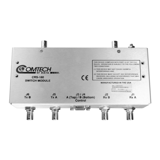
J4 Control B Figure 3-3. CRS-180 – Modem Side Connectors 3.2.1.1 IF Connectors (50Ω BNC) our 50Ω BNC female connectors are provided on the modem side of the CRS-180. Table 3-1. Modem Side Type ‘BNC’ Connectors Ref Des Name Connector Type... -
Page 39: J3 | Control A' Connector (Top) - Modem 'A' (Db-9F)
CRS-180 70/140 MHz IF 1:1 Redundancy Switch MN/CRS180.IOM Switch Connectors and Pinouts Revision 11 3.2.1.2 ‘J3 | Control A’ Connector (Top) – Modem ‘A’ (DB-9F) The Modem ‘A’ Control connector is a 9-pin Type ‘D’ female interface. Pins 2, 3, and 4 carry signals looped through the switch module from Modem ‘B’... -
Page 40: 3.2.2 Antenna Side Connectors
Revision 11 3.2.2 Antenna Side Connectors Two 50Ω female BNC connectors on the antenna side of the CRS-180 (Figure 3-4) provide the coaxial cable connections to the outdoor transmit and receive equipment. See Sect. 1.3.1 in Chapter 1. INTRODUCTION for information about the LED •... -
Page 41: Chapter 4. Modem And Switch Configuration
SWITCH CONFIGURATION Overview To avoid damage to either the modem pair or the CRS-180 switch, it is important that you follow this sequence of configuration: • First, configure both modems for 1:1 redundant operation as directed in this chapter. This... - Page 42 CRS-180 70/140 MHz IF 1:1 Redundancy Switch MN/CRS180.IOM Modem and Switch Configuration Revision 11 BLANK PAGE 4–2...
-
Page 43: Configure The Cdm-625/As For 1:1 Redundancy
CRS-180 70/140 MHz IF 1:1 Redundancy Switch MN/CRS180.IOM Modem and Switch Configuration Revision 11 Configure the CDM-625/As for 1:1 Redundancy • CDM625A Advanced Satellite Modem Installation and Operation Manual (CEFD P/N MN-CDM625A) • CDM625 Advanced Satellite Modem Installation and Operation Manual... -
Page 44: Cdm-625/A Remote User M&C Ethernet Interface
CRS-180 70/140 MHz IF 1:1 Redundancy Switch MN/CRS180.IOM Modem and Switch Configuration Revision 11 4.2.1 CDM-625/A Remote User M&C Ethernet Interface 4.2.1.1 For CDM-625/As Without the Optional IP Packet Processor You may configure one of the CDM-625/A’s four available 10/100 Ethernet ports for M&C Ethernet. -
Page 45: Configure Carrier-In-Carrier® For Redundancy Operation
CRS-180 70/140 MHz IF 1:1 Redundancy Switch MN/CRS180.IOM Modem and Switch Configuration Revision 11 4.2.2 Configure Carrier-in-Carrier® for Redundancy Operation ® The Pre-Mapped Symbol Interface (PMSI) is a function associated with DoubleTalk Carrier-in- ® Carrier that permits the modulator in a selected unit to provide a direct copy of its output (the outbound interferer) to the second modem. - Page 46 CRS-180 70/140 MHz IF 1:1 Redundancy Switch MN/CRS180.IOM Modem and Switch Configuration Revision 11 Notes: 4–6...
-
Page 47: Or Cdm-750 Operation In 1:1 Redundancy
CRS-180 70/140 MHz IF 1:1 Redundancy Switch MN/CRS180.IOM Modem and Switch Configuration Revision 11 CDM-760 or CDM-750 Operation in 1:1 Redundancy • CDM-760 Advanced High-Speed Trunking Modem Installation and Operation Manual (CEFD P/N MN-CDM760) • CDM-750 Advanced High-Speed Trunking Modem Installation and Operation... - Page 48 CRS-180 70/140 MHz IF 1:1 Redundancy Switch MN/CRS180.IOM Modem and Switch Configuration Revision 11 Notes: 4–8...
-
Page 49: Configure The Cdm-570/As For 1:1 Redundancy
Manual (CEFD P/N MN/CDM570L.IOM) • CDM-570A/CDM-570AL/CDMR-570AL Satellite Modem Installation and Operation Manual (CEFD P/N MN-CDM570A) For correct operation of the CRS-180, the CDM-570/A Satellite Modems must have the following installed: • CDM-570A Base Modem Firmware Version 1.1.1 (or higher) •... - Page 50 CRS-180 70/140 MHz IF 1:1 Redundancy Switch MN/CRS180.IOM Modem and Switch Configuration Revision 11 Because the modem automatically detects if it is connected to a 1:1 redundancy system, the steps required to configure both modems are minimal. Modem configuration, monitor and control are possible through local or remote means (Figure 4-1): •...
-
Page 51: Cdm-570/A Non-Ip Redundancy Configuration
Packet Processor is INSTALLED, you must also open the ‘Admin | Pap Save’ page and immediately click [Save PaP Parameters]. Connect all cables to the modems and the CRS-180. This includes the control cable, IF cable and data ‘Y’cables. Chapter 5. CABLES AND CONNECTIONS... -
Page 52: Ip Redundancy Configuration
Use a Layer 2 switch (preferred) or hub to establish an Ethernet connection between the two modems. Before you connect the modems to the CRS-180, you must first use the modem CLI to configure the following CDM-570LAL IP operation settings: •... -
Page 53: Figure 4-2. Cdm-570/A Cli 1:1 Redundancy Configuration Screen
Revision 11 Step Task Power on both modems at the same time. Observe the CRS-180 Online LEDs to see which modem is the Online modem. Monitor the CLIs for both modems to confirm the following: Online modem CLI displays: 1:1 Redundancy (Auto Detected) Redundancy: PARAM File Connection Established. - Page 54 CRS-180 70/140 MHz IF 1:1 Redundancy Switch MN/CRS180.IOM Modem and Switch Configuration Revision 11 Notes: 4–14...
-
Page 55: Configure The Cdm-710G, -710, Or -700S For 1:1 Redundancy
• MN/CDM710.IOM) CDM-700 Satellite Modem Installation and Operation Manual (CEFD P/N • MN/CDM700.IOM) For correct operation of the CRS-180, the CDM-710G, -710, or -700 modems must have the following installed: For the CDM-710G: • o Firmware Version 5.1.1 (or higher) For the CDM-710: •... -
Page 56: Non-Ip Redundancy Configuration
CRS-180. Additionally, you must use a Layer 2 switch to establish an Ethernet connection between each modem. Chapter 5. CABLES AND CONNECTIONS Verify that the ONLINE LEDs for the CRS-180 indicate the same online state as displayed by the modems’ front panel LEDs. 4–16... -
Page 57: Configure Switch Dip Settings
– see your pertinent modem Installation and Operation Manual for detailed explanations. Figure 4-3 shows the DIP switches located on the antenna side of the CRS-180. The table provided here shows the settings that determine “Switch Conditions” – the switchover functionality for a given redundancy configuration. - Page 58 CRS-180 70/140 MHz IF 1:1 Redundancy Switch MN/CRS180.IOM Modem and Switch Configuration Revision 11 Notes: 4–18...
-
Page 59: Chapter 5. Cables And Connections
(one Redundant Modem, one Traffic Modem), you must also purchase a redundancy kit tailored to that modem choice. Each kit provides the CRS-180 70/140 MHz IF 1:1 Redundancy Switch module, plus all cables and components required for interconnection of the redundant configuration to various interfaces (i.e., control, IF, and data) excluding Ethernet,... - Page 60 CRS-180 70/140 MHz IF 1:1 Redundancy Switch MN/CRS180.IOM Cables and Connections Revision 11 5) The modem-specific sections in this chapter identify the required redundancy kit. Specific interface cabling examples are further identified: • Sect. 5.2 Cabling to the CDM-625 or CDM-625A •...
-
Page 61: Cabling To The Cdm-625 Or Cdm-625A
CDM-625/A terrestrial data interface configuration and connection examples and details. You must use the Comtech EF Data KT-0000159 1:1 Redundancy Control/IF Interface Cabling Kit for your control and IF switch-to-modem cabling connections: KT-0000159 1:1 Redundancy Control / IF Interface Cabling Kit (CRS-180CDM-625/A) Ch. -
Page 62: Switch-To-Modem Control Interface Connection
1) Excluding modems, the KT-0000159 1:1 Redundancy Kit (see Sect. 5.2.1) provides all components shown in Figure 5-1. 2) When you connect the Control Interface cable between the CRS-180 and the modems, make sure that you securely fasten the screw locks on the Type ‘D’... -
Page 63: Switch-To-Modem If Interface Connection
EXAMPLE: The Tx IF from ‘MODEM A’ connects to the Tx IF port ‘J5 | Tx A’ on the CRS-180; similarly, the Tx IF from ‘MODEM B’ connects to the Tx IF port ‘J6 | Tx B’ on the CRS-180. -
Page 64: Modem-To-User Data Interface Connections And Examples
CRS-180 70/140 MHz IF 1:1 Redundancy Switch MN/CRS180.IOM Cables and Connections Revision 11 5.2.2 Modem-to-User Data Interface Connections and Examples 5.2.2.1 Modem-to-User Non-IP Data Interface Connections and Examples The data cables and components identified in each of the examples that follow in this section must be purchased separately, as required. -
Page 65: Eia-422/232 Interface Example
CRS-180 70/140 MHz IF 1:1 Redundancy Switch MN/CRS180.IOM Cables and Connections Revision 11 5.2.2.1.1 EIA-422/232 Interface Example CEFD P/N Description CA/RB10461-1 Cable – 1:1 ‘Y’ Splitter, (2X) DB-25MDB-25F Figure 5-4. CDM-625/A EIA-422/232 1:1 Example 5.2.2.1.2 HSSI Interface Example CEFD P/N... -
Page 66: Quad E1 Interface Example
CRS-180 70/140 MHz IF 1:1 Redundancy Switch MN/CRS180.IOM Cables and Connections Revision 11 5.2.2.1.3 Quad E1 Interface Example The G.703 Balanced and Auxiliary G.703 DB-9F single connectors are used for Quad E1 operation. 1) As shown in Figure 5-6, the CA-0000071 ‘Y’ Cable provides for two ports of E1 (i.e., Ports 1/2 -or- Ports 3/4). -
Page 67: G.703 Balanced Interface Example
CRS-180 70/140 MHz IF 1:1 Redundancy Switch MN/CRS180.IOM Cables and Connections Revision 11 5.2.2.1.4 G.703 Balanced Interface Example CEFD P/N Description CA-0000071 Cable – 1:1 ‘Y’ Splitter, (2X) DB-9MDB-9F, 8” Figure 5-7. CDM-625/A G.703 Balanced 1:1 Example 5.2.2.1.5 G.703 Unbalanced Interface Example KT/10553-1 G.703 Unbalanced Interface Kit... -
Page 68: Asi Interface Example
CRS-180 70/140 MHz IF 1:1 Redundancy Switch MN/CRS180.IOM Cables and Connections Revision 11 5.2.2.1.6 ASI Interface Example KT/12579 ASI 75Ω Interface Kit CEFD P/N Description CA/BNC75OHM Cable – IF BNC, 75Ω, 1’ RF/SA32KC-IN/OUT Combiner – 2-way w/Bracket, 0.25-300 MHz, 75Ω BNC Figure 5-9. -
Page 69: Engineering Service Channel (Esc) Interface Example
CRS-180 70/140 MHz IF 1:1 Redundancy Switch MN/CRS180.IOM Cables and Connections Revision 11 5.2.2.1.8 Engineering Service Channel (ESC) Interface Example CEFD P/N Description CA-0000071 Cable – 1:1 ‘Y’ Splitter, (2X) DB-9MDB-9F, 8” Figure 5-11. CDM-625/A ESC 1:1 Example 5–11... -
Page 70: Modem-To-User Ip (10/100 Ethernet) Interface Examples
CRS-180 70/140 MHz IF 1:1 Redundancy Switch MN/CRS180.IOM Cables and Connections Revision 11 5.2.2.2 Modem-to-User IP (10/100 Ethernet) Interface Examples 5.2.2.2.1 Data Interface Connections Using IP Sub-Mux • Chapter 15. IP SUB-MUX in CDM-625 Advanced Satellite Modem Installation and Operation Manual (CEFD P/N MN-CDM625) •... - Page 71 CRS-180 70/140 MHz IF 1:1 Redundancy Switch MN/CRS180.IOM Cables and Connections Revision 11 Figure 5-12. CDM-625/A Block Diagram – 10/100 Ethernet Interface Managed Switch Mode 5–13...
- Page 72 CRS-180 70/140 MHz IF 1:1 Redundancy Switch MN/CRS180.IOM Cables and Connections Revision 11 Figure 5-13. CDM-625/A 10/100 Ethernet 1:1 Example – Managed Switch Mode (with/without Dedicated Management Port) 5–14...
-
Page 73: Router Mode (Requires Optional Ip Packet Processor)
CRS-180 70/140 MHz IF 1:1 Redundancy Switch MN/CRS180.IOM Cables and Connections Revision 11 5.2.2.2.3 Router Mode (Requires Optional IP Packet Processor) When the optional IP Packet Processor is installed and enabled, you should use Port 1 of each modem for M&C purposes only. Reserve use of Port 2, 3, or 4 for each modem for Ethernet traffic only. - Page 74 CRS-180 70/140 MHz IF 1:1 Redundancy Switch MN/CRS180.IOM Cables and Connections Revision 11 Figure 5-15. CDM-625/A 10/100 Ethernet Cabling 1:1 Example – Router Mode 5–16...
-
Page 75: Pmsi Interface Example
Use of PMSI requires that you connect and secure the CDM-625/A Multi-drop CnC Plus 1:1 Cable CA-0000276 (2X DB-9M, 1’) between the Redundant Modem and the Traffic Modem using CnC. See Figure 5-16. The CA-0000276 Multi-Drop CnC PLUS 1:1 Cable bypasses the CRS-180 L-Band 1:1 Redundancy Switch. CEFD P/N Description CA-0000276 CDM-625/A Data Cable –... -
Page 76: Cabling To The Cdm-760 Or Cdm-750
CDM-760/-750 terrestrial data interface configuration and connection examples and details. You must use the Comtech EF Data KT-0000177 1:1 Redundancy Control/IF Interface Cabling Kit for your control and IF switch-to-modem cabling connections. Figure 5-17 shows the kit parts list and connection details. - Page 77 CRS-180 70/140 MHz IF 1:1 Redundancy Switch MN/CRS180.IOM Cables and Connections Revision 11 KT-0000177 70/140 MHz IF 1:1 Redundancy Kit (CRS-180CDM-760, CDM-750) Item CEFD P/N Description PL/11560-1 Top Assy, CRS-180 70/140 MHz IF 1:1 Redundancy Switch XF/BNC-MF-50-75 Transformer, 50-75Ω, 2-200 MHz, BNC, M/F...
-
Page 78: Modem-To-User Data Interface Connections And Examples
CRS-180 70/140 MHz IF 1:1 Redundancy Switch MN/CRS180.IOM Cables and Connections Revision 11 5.3.2 Modem-to-User Data Interface Connections and Examples In addition to the control and IF switch-to-modem cabling shown in the previous section, a number of data interface configuration kits are available for use with the CDM-760 or CDM-750. -
Page 79: Optional Optical Gigabit Ethernet Interface Example
CRS-180 70/140 MHz IF 1:1 Redundancy Switch MN/CRS180.IOM Cables and Connections Revision 11 5.3.2.2 Optional Optical Gigabit Ethernet Interface Example Figure 5-19 shows a CDM-760/-750 1:1 modem configuration that uses the FAST-activated ‘J7 | OPTICAL’ SFP port with the optional Optical Gigabit Ethernet Interface module (CEFD P/N IC-0000058). -
Page 80: Non-Ip Data Interface Kit And Connection Examples
CRS-180 70/140 MHz IF 1:1 Redundancy Switch MN/CRS180.IOM Cables and Connections Revision 11 5.3.2.3 Non-IP Data Interface Kit and Connection Examples While different data interface cards may be installed into both PIIC (Plug-In Interface Card) slots, only one data interface type is operable at a given time. The... -
Page 81: Piic Kt/12542 Single G.703 E3/T3 75Ω Interface Kit
CRS-180 70/140 MHz IF 1:1 Redundancy Switch MN/CRS180.IOM Cables and Connections Revision 11 5.3.2.3.1 PIIC KT/12542 Single G.703 E3/T3 75Ω Interface Kit KT/12542 Single G.703 E3/T3 75Ω Interface Cabling Kit (G.703 E3/T3 75Ω PIIC) CEFD P/N Description CA/BNC75OHM Cable – IF, BNC 75Ω, 1’... - Page 82 CRS-180 70/140 MHz IF 1:1 Redundancy Switch MN/CRS180.IOM Cables and Connections Revision 11 Notes: 5–24...
-
Page 83: Cabling To The Cdm-570 Or Cdm-570A
Figure 5-22 and Figure 5-23 show how to connect a pair of CDM-570/A modems together with the CRS-180; the table for each figure lists the cable assemblies provided in the KT/11559 kit for this initial setup. See Sect. 5.4.1.1 for the CDM-570/A Modem-to-Switch Control Interface connection, and Sect. -
Page 84: Switch-To-Modem Control Interface Connection
1) Excluding the modems, the KT/11599 1:1 Redundancy Control/IF Interface Cabling Kit (see Sect.5.4.1) provides all components shown in Figure 5-22. 2) When you connect the Control Interface cables between the CRS-180 and the modems, make sure that you securely fasten the screw locks on the Type ‘D’... -
Page 85: Switch-To-Modem If Interface Connection
EXAMPLE: The Tx IF from ‘MODEM A’ connects to the Tx IF port ‘J5 | Tx A’ on the CRS-180; similarly, the Tx IF from ‘MODEM B’ connects to the Tx IF port ‘J6 | Tx B’ on the CRS-180. -
Page 86: 5.4.2 Modem-To-User Data Interface Connections And Examples
CRS-180 70/140 MHz IF 1:1 Redundancy Switch MN/CRS180.IOM Cables and Connections Revision 11 5.4.2 Modem-to-User Data Interface Connections and Examples In addition to the control and IF switch-to-modem cabling shown previously, a number of data interface configurations are available for the CDM-570/A. -
Page 87: Eia-422/232 Interface Example
CRS-180 70/140 MHz IF 1:1 Redundancy Switch MN/CRS180.IOM Cables and Connections Revision 11 5.4.2.1.1 EIA-422/232 Interface Example CEFD P/N Description CA/RB10461-1 Cable – 1:1 ‘Y’ Splitter, (2X) DB-25MDB-25F Figure 5-25. CDM-570/A EIA-422/232 1:1 Example 5.4.2.1.2 G.703 Balanced Interface Example CEFD P/N... -
Page 88: G.703 Unbalanced Interface Example
CRS-180 70/140 MHz IF 1:1 Redundancy Switch MN/CRS180.IOM Cables and Connections Revision 11 5.4.2.1.3 G.703 Unbalanced Interface Example G.703 Unbalanced 1:1 Interface Kit KT/10553-1 CEFD P/N Description CA/BNC75OHM Cable – IF BNC, 1’ CN/BNC-TEE-JPJ T-Adapter, 50Ω BNC Figure 5-27. CDM-570/A G.703 Unbalanced 1:1 Example... -
Page 89: Modem-To-User Ip (10/100 Ethernet) Interface Example
CRS-180 70/140 MHz IF 1:1 Redundancy Switch MN/CRS180.IOM Cables and Connections Revision 11 5.4.2.2 Modem-to-User IP (10/100 Ethernet) Interface Example Figure 5-28 shows the block diagram and cabling example of a CDM-570/A 1:1 modem configuration using the optional IP (10/100 Ethernet) Module (CDM-570) or Packet Processor (CDM-570A) interface. - Page 90 CRS-180 70/140 MHz IF 1:1 Redundancy Switch MN/CRS180.IOM Cables and Connections Revision 11 Notes: 5–32...
-
Page 91: Cabling To The Cdm-710G
CRS-180CDM-710G Control and IF Interface Connections Using Cabling Kit KT/12554 Figure 5-29 shows the CRS-180-to-CDM-710G control and IF interface connections. The Comtech EF Data KT/12554 CRS-180 70/140 MHz IF 1:1 Redundancy Kit provides all control and IF connection components. Figure 5-29 NOTES: 1) Use of the XF/BNC-MF-50-75 transformers (Item 2) is required on the ‘J7 | Rx’... - Page 92 KT/12554 70/140 MHz IF 1:1 Redundancy Kit (CRS180CDM-7190G) Item CEFD P/N Description PL/11560-1 Top Assy, CRS-180 70/140 MHz IF 1:1 Redundancy Switch XF/BNC-MF-50-75 Transformer, 50-75Ω, 2-200 MHz, BNC, M/F Notes 1,2 PL/0813-4 Note 2 Cable, Special, IF BNC, 75Ω...
-
Page 93: Modem-To-User Data Interface Kit And Connection Examples
CRS-180 70/140 MHz IF 1:1 Redundancy Switch MN/CRS180.IOM Cables and Connections Revision 11 5.5.2 Modem-to-User Data Interface Kit and Connection Examples In addition to the basic Modem-to-Switch cabling shown previously, a number of data interface configuration kits are available for use with the CDM-710G High-Speed Satellite Modem. -
Page 94: Single G.703 E3/T3/Sts-1 75Ω Data Interface (Cdi-10-1) Kit Kt/12583
CRS-180 70/140 MHz IF 1:1 Redundancy Switch MN/CRS180.IOM Cables and Connections Revision 11 5.5.2.1.1 Single G.703 E3/T3/STS-1 75Ω Data Interface (CDI-10-1) Kit KT/12583 Figure 5-31 shows an example of a CDM-710G 1:1 modem configuration with the CDI-10-1 Single G.703 Data Interface installed in Slot 1, with Slot 2 empty. The figure depicts installation of one KT/12583 Single G.703 Interface Kit. -
Page 95: Hssi Data Interface (Cdi-60) Kit Kt/12586
CRS-180 70/140 MHz IF 1:1 Redundancy Switch MN/CRS180.IOM Cables and Connections Revision 11 5.5.2.1.2 HSSI Data Interface (CDI-60) Kit KT/12586 Figure 5-32 shows an example of a CDM-710G 1:1 modem configuration with the CDI-60 HSSI Data Interface installed in Slot 1, with Slot 2 empty. The figure depicts installation of one KT/12586 HSSI Interface Kit. -
Page 96: Gigabit Ethernet Interface (Cdi-70) Example
CRS-180 70/140 MHz IF 1:1 Redundancy Switch MN/CRS180.IOM Cables and Connections Revision 11 5.5.2.2 Gigabit Ethernet Interface (CDI-70) Example See CEFD White Paper “Bridged Ethernet Interface Redundancy” available for download from Comtech EF Data’s Web site (www.comtechefdata.com). Figure 5-33 shows the block diagram and cabling example for a CDM-710G 1:1 modem configuration with the CDI-70 Gigabit Ethernet Data Interface installed in Slot 2, with Slot 1 empty. -
Page 97: Cabling To The Cdm-710
You must order terrestrial data interface components/kits separately. See Sect. 5.6.2 for more information. You must use the Comtech EF Data KT/12551 CRS-180 70/140 MHz IF 1:1 Redundancy Kit for all control and IF connections. Figure 5-34 shows these Switch-to-Modem control and IF interface connections. - Page 98 Revision 11 KT/12554 70/140 MHz IF 1:1 Redundancy Kit Item CEFD P/N Description PL/11560-1 Top Assy, CRS-180 70/140 MHz IF 1:1 Redundancy Switch XF/BNC-MF-50-75 Transformer, 50-75Ω, 2-200 MHz, BNC, M/F Notes 1,2 PL/0813-4 Cable, Special, IF BNC, 75Ω Note 2 PL/0946-1 Cable, Special, IF BNC, 50Ω...
-
Page 99: Modem-To-User Data Interface Kit And Connection Examples
CRS-180 70/140 MHz IF 1:1 Redundancy Switch MN/CRS180.IOM Cables and Connections Revision 11 5.6.2 Modem-to-User Data Interface Kit and Connection Examples In addition to the basic Modem-to-Switch cabling shown previously, a number of data interface configuration kits are available for use with the CDM-710 Broadcast Satellite Modem. Separate cabling kits are needed for these CDM-710 data interfaces. -
Page 100: Asi 75Ω Data Interface (Cdi-40) Kit Kt/12579
CRS-180 70/140 MHz IF 1:1 Redundancy Switch MN/CRS180.IOM Cables and Connections Revision 11 5.6.2.1.1 ASI 75Ω Data Interface (CDI-40) Kit KT/12579 Figure 5-36 shows an example of a CDM-710 1:1 modem configuration with the CDI-40 ASI Data Interface installed in Slot 1, with Slot 2 empty. The figure depicts installation of one KT/12579 ASI Interface Kit. -
Page 101: Hssi Data Interface (Cdi-60) Interface Kit Kt/12578
CRS-180 70/140 MHz IF 1:1 Redundancy Switch MN/CRS180.IOM Cables and Connections Revision 11 5.6.2.1.2 HSSI Data Interface (CDI-60) Interface Kit KT/12578 Figure 5-37 shows an example of a CDM-710 1:1 modem configuration with the CDI-60 HSSI Data Interface installed in Slot 1, with Slot 2 empty. The figure depicts installation of one KT/12578 HSSI Interface Kit. -
Page 102: Gigabit Ethernet Data Interface (Cdi-70) Example
CRS-180 70/140 MHz IF 1:1 Redundancy Switch MN/CRS180.IOM Cables and Connections Revision 11 5.6.2.2 Gigabit Ethernet Data Interface (CDI-70) Example See CEFD White Paper “Bridged Ethernet Interface Redundancy” available for download from Comtech EF Data’s Web site (www.comtechefdata.com). Figure 5-38 shows the block diagram and cabling example of a CDM-710 1:1 modem configuration with a CDI-70 Gigabit Ethernet Data Interface in Slot 2, with Slot 1 empty. -
Page 103: Cabling To The Cdm-700
You must order terrestrial data interface components/kits separately. See Sect. 5.7.2 for more information. You must use the Comtech EF Data KT/12554 CRS-180 70/140 MHz IF 1:1 Redundancy Kit for your control and IF connections. Figure 5-39 shows these Switch-to-Modem control and IF interface connections. - Page 104 Revision 11 KT/12554 70/140 MHz IF 1:1 Redundancy Kit Item CEFD P/N Description PL/11560-1 Top Assy, CRS-180 70/140 MHz IF 1:1 Redundancy Switch XF/BNC-MF-50-75 Transformer, 50-75Ω, 2-200 MHz, BNC, M/F Notes 1,2 PL/0813-4 Note 2 Cable, Special, IF BNC, 75Ω...
-
Page 105: Modem-To-User Data Interface Kit And Connection Examples
CRS-180 70/140 MHz IF 1:1 Redundancy Switch MN/CRS180.IOM Cables and Connections Revision 11 5.7.2 Modem-to-User Data Interface Kit and Connection Examples In addition to the basic Modem-to-Switch cabling shown previously, a number of data interface configuration kits are available for use with the CDM-700 Satellite Modem. Separate cabling kits are needed for these data interfaces. -
Page 106: Dual G.703 E3/T3/Sts-1 75Ω Data Interface (Cdi-10) Kit Kt/12542 And Hssi Data Interface (Cdi-60) Kit Kt/12578
CRS-180 70/140 MHz IF 1:1 Redundancy Switch MN/CRS180.IOM Cables and Connections Revision 11 Figure 5-40 shows the block diagram typical for the kits shown in Sects. 5.7.2.1.1 through 5.7.2.1.3. Separate interface cabling kits are needed for these CDM-700 data interfaces. For example, Sect. -
Page 107: 155Mb Copper Data Interface (Cdi-50) Kit Kt/12579
CRS-180 70/140 MHz IF 1:1 Redundancy Switch MN/CRS180.IOM Cables and Connections Revision 11 5.7.2.1.2 155MB Copper Data Interface (CDI-50) Kit KT/12579 Figure 5-42 shows an example of a CDM-700 1:1 modem configuration with a CDI-50 Data Interface installed in Slot 1 for use with 155MB Copper data, with Slot 2 empty. This figure depicts installation of one KT/12579 155MB Copper Interface Kit –... -
Page 108: Data Interface (Cdi-50) Kits Kt/12580 (Single-Mode) Or Kt/12581 (Multi-Mode)
CRS-180 70/140 MHz IF 1:1 Redundancy Switch MN/CRS180.IOM Cables and Connections Revision 11 5.7.2.1.3 OC-3 Data Interface (CDI-50) Kits KT/12580 (Single-Mode) or KT/12581 (Multi-Mode) Figure 5-43 shows a CDM-700 1:1 modem configuration with installation of one CDI-50 data interface installed in Slot 1 for use with OC-3 data, with Slot 2 empty. This figure shows installation of one KT/12585 OC-3 Single-Mode Interface Kit. -
Page 109: Gigabit Ethernet Data Interface (Cdi-70) Example
CRS-180 70/140 MHz IF 1:1 Redundancy Switch MN/CRS180.IOM Cables and Connections Revision 11 5.7.2.2 Gigabit Ethernet Data Interface (CDI-70) Example See CEFD White Paper “Bridged Ethernet Interface Redundancy” available for download from Comtech EF Data’s Web site (www.comtechefdata.com). Figure 5-44 shows an example of a CDM-700 1:1 modem configuration with a CDI-70 Gigabit Ethernet Data Interface installed in Slot 1, with Slot 2 empty. - Page 110 CRS-180 70/140 MHz IF 1:1 Redundancy Switch MN/CRS180.IOM Cables and Connections Revision 11 Notes: 5–52...
-
Page 111: Appendix A. Cable Drawings
Appendix A. CABLE DRAWINGS Overview This appendix provides technical specification drawings for the cables used with the CRS-180 70/140 MHz IF 1:1 Redundancy Switch. These cables are divided into two categories – Control Interface Cables (Section A.2), and IF/Data Interface Cables (Section A.3). -
Page 112: Control Interface Cables
CRS-180 70/140 MHz IF 1:1 Redundancy Switch MN/CRS180.IOM Appendix A Revision 11 Control Interface Cables App. A CABLE REF Ch. 5 DESCRIPTION USED WITH CRS-180 USED FOR (TYPE) CEFD P/N Universal Control Cable, DB-9MDB-9M, 4’ CDM-625/A CDM-760/-750 5-17 CA/WR9378-4... -
Page 113: Switch-To-Modem, Universal Control Cable, Db-9MDb-9M
CRS-180 70/140 MHz IF 1:1 Redundancy Switch MN/CRS180.IOM Appendix A Revision 11 A.2.1 Switch-to-Modem, Universal Control Cable, DB-9MDB-9M Alternate Cabling Note: CEFD Universal Control Cable CA/WR9378-8 (DB-9M DB-9M, 8’), sold separately, is available for use in place of CA/WR9378-4... -
Page 114: Switch-To-Modem, Adapter Control Cable, Rohs, Db-9MDb-15F
CRS-180 70/140 MHz IF 1:1 Redundancy Switch MN/CRS180.IOM Appendix A Revision 11 A.2.2 Switch-to-Modem, Adapter Control Cable, RoHS, DB-9MDB-15F Figure A-2. Adapter Control Cable (CA/WR12135-1) -
Page 115: Switch-To-Modem, Optional 'Y' Splitter Adapter Control Cable, (2X) Db-9MDb-15F
CRS-180 70/140 MHz IF 1:1 Redundancy Switch MN/CRS180.IOM Appendix A Revision 11 A.2.3 Switch-to-Modem, Optional ‘Y’ Splitter Adapter Control Cable, (2X) DB-9MDB-15F You may purchase this optional CA/WR13011-4 ‘Y’ Splitter Adapter Control Cable as a replacement for the CA/WA12135-1 cable. This cable permits user access to the Summary Fault Relay. -
Page 116: Switch-To-Modem, Optional Control Cable, Non-Muting, Db-9MDb-15F
CRS-180 70/140 MHz IF 1:1 Redundancy Switch MN/CRS180.IOM Appendix A Revision 11 A.2.4 Switch-to-Modem, Optional Control Cable, Non-muting, DB-9MDB-15F You may purchase this optional CA-0000187 Control Cable as a replacement for the CA/WA12135-1 cable. This cable keeps the offline modem’s Tx IF-enabled. -
Page 117: If / Data Interface Cables
CRS-180 70/140 MHz IF 1:1 Redundancy Switch MN/CRS180.IOM Appendix A Revision 11 IF / Data Interface Cables App. A CABLE REF Ch. 5 DESCRIPTION USED FOR (TYPE) USED WITH CRS-180 CEFD P/N CDM-625/A CDM-710G 5-29 PL/0946-1 Cable – RoHS Coaxial, BNC 50Ω, 4’... - Page 118 CRS-180 70/140 MHz IF 1:1 Redundancy Switch MN/CRS180.IOM Appendix A Revision 11 App. A CABLE REF Ch. 5 DESCRIPTION USED FOR (TYPE) USED WITH CRS-180 CEFD P/N CDM-760/-750 5-17 CDM-710G 5-29 A-14 PL/0813-4 Cable – RoHS Coaxial, BNC 75ΩBNC 75Ω, 4’...
-
Page 119: Switch-To-Modem / Modem-To-User, Coaxial Cable, Rohs, Bnc 50Ω
CRS-180 70/140 MHz IF 1:1 Redundancy Switch MN/CRS180.IOM Appendix A Revision 11 A.3.1 Switch-to-Modem / Modem-to-User, Coaxial Cable, RoHS, BNC 50Ω Figure A-5. Tx/Rx BNC 50Ω RoHS Coaxial Cable (PL/0946-1) -
Page 120: Switch-To-Modem / Modem-To-User, Coaxial Cable, Rohs, Bnc 75Ω
CRS-180 70/140 MHz IF 1:1 Redundancy Switch MN/CRS180.IOM Appendix A Revision 11 A.3.2 Switch-to-Modem / Modem-to-User, Coaxial Cable, RoHS, BNC 75Ω Figure A-6. User Data BNC 75Ω RoHS Coaxial Cable (CA/BNC75OHM) A-10... -
Page 121: Modem-To-User, Splitter Cable, Db-25F(2X) Db-25M
CRS-180 70/140 MHz IF 1:1 Redundancy Switch MN/CRS180.IOM Appendix A Revision 11 A.3.3 Modem-to-User, Splitter Cable, DB-25F(2X) DB-25M Figure A-7. 1:1 User Data Splitter Cable (CA/RB10461-1) A-11... -
Page 122: Modem-To-User, Cdm-625/A Data 'Y' Splitter Cable, Db-9F(2X) Db-9M
CRS-180 70/140 MHz IF 1:1 Redundancy Switch MN/CRS180.IOM Appendix A Revision 11 A.3.4 Modem-to-User, CDM-625/A Data ‘Y’ Splitter Cable, DB-9F(2X) DB-9M Figure A-8. 1:1 User Data ‘Y’ Splitter Cable (CA-0000071) A-12... -
Page 123: Modem-To-User, Quad E1 'Y' Splitter Adapter Cable, Db-9M(2X) Db-15F
CRS-180 70/140 MHz IF 1:1 Redundancy Switch MN/CRS180.IOM Appendix A Revision 11 A.3.5 Modem-to-User, Quad E1 ‘Y’ Splitter Adapter Cable, DB-9M(2X) DB-15F You may purchase this optional adapter cable to adapt the Balanced G.703 or Auxiliary G.703 DB-9F modem connections to a DB-15F connector pair. -
Page 124: Modem-To-User, Quad E1 'Y' Splitter Adapter Cable, Db-9M(2X) Rj-48F
CRS-180 70/140 MHz IF 1:1 Redundancy Switch MN/CRS180.IOM Appendix A Revision 11 A.3.6 Modem-to-User, Quad E1 ‘Y’ Splitter Adapter Cable, DB-9M(2X) RJ-48F You may purchase this optional adapter cable to adapt the Balanced G.703 or Auxiliary G.703 DB-9F modem connections to a RJ-48F connector pair. -
Page 125: Modem-To-User, Quad E1 'Y' Splitter Adapter Cable Kit
CRS-180 70/140 MHz IF 1:1 Redundancy Switch MN/CRS180.IOM Appendix A Revision 11 A.3.7 Modem-to-User, Quad E1 ‘Y’ Splitter Adapter Cable Kit KT-0000122 Quad E1 Balanced/Unbalanced Adapter Kit CEFD PART NO. DESCRIPTION CA-0000347 ‘Y’ Cable Assy: DB-9M 2X RJ-48 Male 502-0532-001 Bolun Adapter, 2X RJ-48 Female ... -
Page 126: Modem-To-User, Overhead User Data 'Y' Splitter Cable, Hd-44F(2X) Hd-44M
CRS-180 70/140 MHz IF 1:1 Redundancy Switch MN/CRS180.IOM Appendix A Revision 11 A.3.8 Modem-to-User, Overhead User Data ‘Y’ Splitter Cable, HD-44F(2X) HD-44M Figure A-12. Overhead User Data ‘Y’ Splitter Cable (CA-0000070) A-16... -
Page 127: Modem-To-Modem, Cdm-625/A Shielded Multi-Drop Cnc
CRS-180 70/140 MHz IF 1:1 Redundancy Switch MN/CRS180.IOM Appendix A Revision 11 ® A.3.9 Modem-to-Modem, CDM-625/A Shielded Multi-drop CnC Plus Cable, DB-9MDB-9M ® Figure A-13. CDM-625/A Shielded Multi-drop CnC Plus Modem-to-Modem Cable (CA-0000276) A-17... -
Page 128: Switch-To-Modem / Modem-To-User, Rohs Coax Cable, Bnc 75Ω
CRS-180 70/140 MHz IF 1:1 Redundancy Switch MN/CRS180.IOM Appendix A Revision 11 A.3.10 Switch-to-Modem / Modem-to-User, RoHS Coax Cable, BNC 75Ω Figure A-14. Tx/Rx BNC 75Ω RoHS Coax Cable (PL/0813-4) A-18... -
Page 129: Modem-To-User, Optical Gigabit Ethernet Cable Assemblies, Rohs, Single-Mode Or Multi-Mode, (2X) Type 'Lc' (4X) Type 'Lc
CRS-180 70/140 MHz IF 1:1 Redundancy Switch MN/CRS180.IOM Appendix A Revision 11 A.3.11 Modem-to-User, Optical Gigabit Ethernet Cable Assemblies, RoHS, Single-Mode OR Multi- Mode, (2X) Type ‘LC’ (4X) Type ‘LC’ CEFD PART NO. Description Comments ‘Y’ Cable Assy – RoHS-Compliant, Optical Coupler (Single-Mode),... -
Page 130: Modem-To-User, G.703 Balanced User Data 'Y' Splitter Cable, Db-15M(2X) Db-15M
CRS-180 70/140 MHz IF 1:1 Redundancy Switch MN/CRS180.IOM Appendix A Revision 11 A.3.12 Modem-to-User, G.703 Balanced User Data ‘Y’ Splitter Cable, DB-15M(2X) DB-15M Figure A-16. G.703 Balanced User Data ‘Y’ Splitter Cable (CA/WR10522-1) A-20... -
Page 131: Modem-To-User, Hssi User Data 'Y' Splitter Cable, Hd-50F(2X) Hd-50M
CRS-180 70/140 MHz IF 1:1 Redundancy Switch MN/CRS180.IOM Appendix A Revision 11 A.3.13 Modem-to-User, HSSI User Data ‘Y’ Splitter Cable, HD-50F(2X) HD-50M Figure A-17. HSSI User Data ‘Y’ Splitter Cable (PP/SC3523) A-21... -
Page 132: Modem-To-User, Oc-3 Cable Assemblies, Rohs, Single-Mode Or Multi-Mode, Type 'Sc/Upc' (2X) Type 'Sc/Upc
CRS-180 70/140 MHz IF 1:1 Redundancy Switch MN/CRS180.IOM Appendix A Revision 11 A.3.14 Modem-to-User, OC-3 Cable Assemblies, RoHS, Single-Mode OR Multi-Mode, Type ‘SC/UPC’ (2X) Type ‘SC/UPC’ CEFD PART NO. Description Comments ‘Y’ Cable Assy – RoHS-Compliant, Optical Coupler (Single-Mode), 7’, PP/CPS2A12501 For CDM-700 Single-Mode OC-3 Interface;... - Page 134 2114 85281 WEST TH STREET TEMPE ARIZONA 480 • 333 • 2200 PHONE 480 • 333 • 2161...
Need help?
Do you have a question about the CRS-180 and is the answer not in the manual?
Questions and answers