
Related Manuals for Comtech EF Data SMS-7000


Summary of Contents for Comtech EF Data SMS-7000
- Page 1 SMS-7000 Modem Protection Switch Installation and Operation Manual Part Number MN/SMS7000.IOM Revision 3...
- Page 3 Errata A Comtech EF Data Documentation Update Subject: Changes to Table 3-4 (Interface Configuration Jumper Settings) Date: October 5, 2001 Document: SMS-7000 Modem Protection Switch Installation and Operation Manual, Revision 3, September 30, 1999 Part Number: MN/SMS7000.EA3 Collating Instructions: Attach this page to page 2-11 Comments: The following changes provide updated information for Figure2-2.
- Page 4 10-32x ½ Socket Head Screw (4) #10 Flat Latch Washers Striker Plate FP/5154 Black Latch Hinge Knobs Latch LATCH04 Panel FP/5153 Latch Striker Plate FP/5154 1/4-20x1/4 Socket Head Shoulder Screw (2) Fiber Washers Fiber Left Hinge Washers Mounting Plate FP/5152-2 Hinge Base FP/5151...
- Page 5 Comtech EFData Documentation Update Subject: Changes to Table 3-4 (Initial Defaults) Date: October 5, 2001 Document: SMS-7000 Modem protection Switch Installation and Operation Manual, Rev. 3, dated September 30, 1999 Part Number: MN/SMS7000.EB3 Collating Instructions: Attach this page to page 3-33 Comments: The following changes provide updated information to Table 3-4.
-
Page 7: Related Documents
The following documents are referenced in this manual: • Department of Defense (DOD) MIL-STD-188-114A, “Electrical Characteristics of Digital Interface Circuits” • M-2000 Multiplexer Installation and Operation Manual • Comtech EF Data CRS-280L 1:N Redundancy Switch Installation and Operation Manual Filename: T_ERRATA... - Page 9 SMS-7000 Modem Protection Switch Installation and Operation Manual Comtech EFData is an ISO 9001 Registered Company. Part Number MN/SMS7000.IOM Revision 3 September 30, 1999 Copyright © Comtech EFData, 2000. All rights reserved. Printed in the USA. Comtech EFData, 2114 West 7th Street, Tempe, Arizona 85281 USA, (480) 333-2200, FAX: (480) 333-2161.
-
Page 10: Customer Support
Customer Support Contact the Comtech EFData Customer Support Department for: • Product support or training • Information on upgrading or returning a product • Reporting comments or suggestions concerning manuals A Customer Support representative may be reached at: Comtech EFData Attention: Customer Support Department 2114 West 7th Street Tempe, Arizona 85281 USA... -
Page 11: Table Of Contents
Table of Contents Customer Support ..............................ii Overview of Changes to Previous Edition ......................viii Overview of Changes to Previous Edition ......................viii About this Manual ..............................viii EMC Compliance ................................x Warranty Policy................................ xii CHAPTER 1. INTRODUCTION......................1–1 Overview..............................1–2 1.1.1 Compatibility ............................1–2 1.1.2 Data Formats ............................1–4... - Page 12 Preface SMS-7000 Modem Protection Switch Mounting ..............................2–7 2.3.1 Description ...............................2–7 2.3.1.1 Top Mount............................2–7 2.3.1.2 Back Mount .............................2–7 2.3.2 Installation..............................2–8 2.3.2.1 Switch Control Unit.........................2–8 2.3.2.2 Top Mount Installation ........................2–8 2.3.2.3 Back Mount Installation ........................2–10 Cable Installation............................2–13 2.4.1 Interconnecting the Switch Components....................2–13 2.4.1.1...
- Page 13 SMS-7000 Modem Protection Switch Preface 3.4.3 Configuration Dependent Prime 1 through 8 Menu ................3–15 3.4.4 Configuration Load/Verify Menu ......................3–17 3.4.5 Configuration Operation Mode Menu....................3–19 3.4.6 System Status Switching Menu......................3–21 3.4.7 System Status Configuration Menu......................3–23 3.4.8 Faults/Alarms Menu..........................3–25 3.4.9 Stored Faults/Alarms Menu ........................3–27 3.4.10...
- Page 14 Figure 2-5. Typical switch installation ........................2–14 Figure 2-6. SCU rear panel.............................2–22 Figure 2-7. DSU/IFU terrestrial side ........................2–26 Figure 3-1. SMS-7000 front panel view ........................3–1 Figure 3-2. Main menu .............................3–7 Figure 3-3. Configuration backup 1 and 2 menu ......................3–8 Figure 3-4. Configuration independent prime 1 through 8 menu ................3–10 Figure 3-5.
- Page 15 Table 4-1. DSM interfaces............................4–3 Table 4-2. SCU chassis connectors...........................4–4 Table 4-3. SCU rear panel connectors ........................4–5 Table 5-1. Switch fault analysis..........................5–3 Table A-1. SMS-7000 remote control: SMS-658/SMS-758 comparison table ............a–2 Table B-1. SMS-7000/M-2000 50-pin to 37-pin interface cable pinouts ..............b–3 Rev. 3...
-
Page 16: Overview Of Changes To Previous Edition
About this Manual This manual provides installation and operation information for the Comtech EFData SMS-7000 Modem Protection Switch. This is a technical document intended for earth station engineers, technicians, and operators responsible for the operation and maintenance of the SMS-7000. -
Page 17: Cautions And Warnings
SMS-7000 Modem Protection Switch Preface Conventions and References Cautions and Warnings CAUTION indicates a hazardous situation that, if not avoided, may result in minor or moderate injury. CAUTION may also be used to indicate other unsafe practices or risks of property damage. -
Page 18: Emc Compliance
Preface SMS-7000 Modem Protection Switch Reporting Comments or Suggestions Concerning this Manual Comments and suggestions regarding the content and design of this manual will be appreciated. To submit comments, please contact the Comtech EFData Customer Support Department. EMC Compliance EN55022 Compliance This equipment meets EN55022. - Page 19 SMS-7000 Modem Protection Switch Preface Low Voltage Directive (LVD) The following information is applicable for the European Low Voltage Directive (EN60950): <HAR> Type of power cord required for use in the European Community. CAUTION: Double-pole/Neutral Fusing. ACHTUNG: Zweipolige bzw. Neutralleiter-Sicherung.
-
Page 20: Warranty Policy
Preface SMS-7000 Modem Protection Switch Warranty Policy This Comtech EFData product is warranted against defects in material and workmanship for a period of one year from the date of shipment. During the warranty period, Comtech EFData will, at its option, repair or replace products that prove to be defective. -
Page 21: Chapter 1. Introduction
Chapter 1. INTRODUCTION This chapter provides an overview, description, and specifications for the SMS-7000 satellite modem protection switch. The SMS-7000 is hereinafter referred to in this manual as “the switch”, and includes the following components (refer to Figure 1-1): •... -
Page 22: Overview
Introduction SMS-7000 Modem Protection Switch Overview The switch is specifically designed to perform automatic redundancy switching for any combination of up to two backup and eight prime Comtech EFData satellite modems. Up to eight separate uplinks and downlinks can be accessed by the user at any time. -
Page 23: Table 1-1. Sms-7000 Modem Hardware Compatibility
SMS-7000 Modem Protection Switch Introduction For modem compatibility, refer to Table 1-1. Table 1-1. SMS-7000 Modem Hardware Compatibility Rack Setup Backup Comments SDM-308-4 Either SDM-6000 must be configured as Modem Type 1 to be compatible SDM-6000 with SDM-308-4 (M1200P). Note: SDM-6000 must be configured as Modem Type 4 to be compatible with SDM-308-4 (old IDR interface). -
Page 24: Data Formats
Introduction SMS-7000 Modem Protection Switch 1.1.2 Data Formats Table 1-2 lists the data formats that the switch will support. Table 1-2. Data Formats Data Type Connector V.35 Data 25-pin D EIA-422/MIL-STD-188 Data IDR 8K Data Channel 37-pin D G.703 Balanced 15-pin D G.703 Unbalanced... -
Page 25: Options
SMS-7000 Modem Protection Switch Introduction 1.1.3 Options Table 1-3 lists the options that are applicable to the switch. Table 1-3. Options Input Power Mounting Kit IF Switch Switch Type Switch Quantity Option Top KT/5275 No IF Switch Universal None Back KT/5274 75Ω... -
Page 26: Protection Switch
Introduction SMS-7000 Modem Protection Switch 1.1.4 Protection Switch Refer to Table 1-4 for part numbers of various switch component. Table 1-4. Protection Switch Part Number Description PL/4800 Chassis Controller PL/4801-1 IF Switch, 75Ω PL/4801-2 IF Switch, 50Ω PL/4802 Switch, Data... -
Page 27: Figure 1-2. Block Diagram
SMS-7000 Modem Protection Switch Introduction The switch functional block diagram (Figure 1-2) displays the functional partitioning and interconnection between the three chassis. Two cables interconnect the three units. The SCU and DSU are connected via a cable that transfers power, faults, and switch control between the two chassis. Power, modem faults, and switch faults originate from the DSU, while switch control commands are initiated by the SCU. -
Page 28: Switch Controller Unit (Scu)
Introduction SMS-7000 Modem Protection Switch 1.2.1 Switch Controller Unit (SCU) The SCU is a one unit (1U), 19-inch (48.26 cm) rack-mounted chassis that provides the configuration and automatic switching control functions. Rear panel connectors on this chassis provide all user remote control and status interfaces and rack internal control interfaces. -
Page 29: Data Switch Unit (Dsu)
SMS-7000 Modem Protection Switch Introduction 1.2.2 Data Switch Unit (DSU) The DSU performs terrestrial data switch and breakout panel functions. Enclosed in a shallow 4.5-inch (11.4 cm) deep chassis, the DSU is designed to mount within the rack in several ways. This will accommodate particular rack configurations and user terrestrial cable routing. -
Page 30: Figure 1-6. Dsu/Ifu Modem Side
Introduction SMS-7000 Modem Protection Switch The bottom of the DSU encloses two redundant, online-replaceable, low-voltage, power supply modules. The power supply modules service all three chassis and are individually replaceable with no interruption of service. All terrestrial data connections are located on the data switch module face of the DSU (Figure 1-5). -
Page 31: If Switch Unit (Ifu)
SMS-7000 Modem Protection Switch Introduction 1.2.3 IF Switch Unit (IFU) All IF switching is performed in the IFU. In a typical application, the IFU is attached to the DSU. If necessary, the unit can be mounted separately and interconnected with an extended length interface cable. -
Page 32: Specifications
Introduction SMS-7000 Modem Protection Switch Specifications Refer to Table 1-5 for operating specifications of the switch. Table 1-5. SMS-7000 Specifications Operation Number of Service Channels Modular from 1 to 8. Field upgradeable; one data switch module per channel. Number of Backups 1 or 2. - Page 33 SMS-7000 Modem Protection Switch Introduction Table 1-5. SMS-7000 Specifications (Continued) I/O Interfaces Terrestrial Data V.35 Data: 25-pin female D. (Each channel) EIA-422/MIL-STD-188 Data: 37-pin female D. G.703 Balanced Drop and Insert: 15-pin female D. G.703 Unbalanced Drop and Insert: Coax.
- Page 34 Introduction SMS-7000 Modem Protection Switch This page is intentionally left blank. 1–14 Rev. 3...
-
Page 35: Chapter 2. Installation
Chapter 2. INSTALLATION This chapter provides instructions for unpacking and installation, as well as external connection information for the switch. Unpacking The switch (which consists of three sections) and the manual are packaged in pre- formed, reusable, cardboard cartons that contain foam spacing for maximum shipping protection. -
Page 36: Equipment Inspection
Installation SMS-7000 Modem Protection Switch Equipment Inspection 2.2.1 Included Parts A typical switch contains the following components: Note: Parts are not drawn to scale. Description Description SMS-7000 Switch Installation and Operation Manual Cable Assembly, 37-Pin Envelope containing the test data... -
Page 37: Back Mount (Hinged) Hardware Kit
SMS-7000 Modem Protection Switch Installation 2.2.2 Back Mount (Hinged) Hardware Kit Back Mount (Hinged) Hardware Kit (Comtech EFData Part # KT/5274), which includes: Description Description Base Hinge 10-32 x 1/2 Socket Head Cap Screws Comtech EFData Part # HW/10-32X1/2SH Comtech EFData Part # FP/5151... -
Page 38: Top Mount Hardware Kit
Installation SMS-7000 Modem Protection Switch 2.2.3 Top Mount Hardware Kit Top Mounting Hardware Kit (Comtech EFData Part # KT/5275), which includes: Description Description Bracket, Rack Mounted IF Chassis 4-40 x 3/8 Phillips Head Screw Comtech EFData Part # HW/4- 40X3/8P.H. -
Page 39: Cables
SMS-7000 Modem Protection Switch Installation 2.2.4 Cables Notes: 1. The following QTY represents the minimum number of cables. Addition prime and backup modems will require additional cables. 2. Contact Comtech EFData Sales department for information regrading the price and availability of the cables. -
Page 40: Tools Required
Installation SMS-7000 Modem Protection Switch 2.2.5 Tools Required Description 3/8 inch (9 mm) drive ratchet. 3 x 3/8 inch (76 x 9 mm) drive extension. 1/2 x 3/8 inch drive socket. (Metric equivalent: 13mm, 6 pt.) 3/8 x 3/8 inch drive socket. (Metric equivalent: 9mm, 6 pt.) -
Page 41: Mounting
SMS-7000 Modem Protection Switch Installation Mounting Prior to installing the switch in the customer equipment rack, an appropriate mounting configuration must be defined. The switch components are designed for a variety of mounting options to accommodate different user requirements. The Switch Control Unit (SCU) chassis is a one unit (1U), 19-inch (48.3 cm) rack- mountable unit intended for mounting at eye level in the front of the rack. -
Page 42: Installation
Installation SMS-7000 Modem Protection Switch 2.3.2 Installation 2.3.2.1 Switch Control Unit The Switch Control Unit (SCU) arrives fully assembled from the factory. After unpacking the switch, install the switch control unit into the equipment rack and secure with customer-furnished hardware. -
Page 43: Figure 2-1. Top Mount Installation
SMS-7000 Modem Protection Switch Installation Figure 2-1. Top Mount Installation Rev. 3 2–9... -
Page 44: Back Mount Installation
Installation SMS-7000 Modem Protection Switch 2.3.2.3 Back Mount Installation The back mount (hinge) feature provides ready access for installation and service, while making efficient use of rack volume. The Back-Mount Hardware Kit (KT/5274) is intended for (but not restricted to) use in rear-mount applications where clearance and access might create difficulty. -
Page 45: Figure 2-2. Back Mount (Hinge) Installation
SMS-7000 Modem Protection Switch Installation Figure 2-2. Back Mount (Hinge) Installation Rev. 3 2–11... -
Page 46: Figure 2-3. Hinge Mount, Side View
Installation SMS-7000 Modem Protection Switch Figure 2-3. Hinge Mount, Side View Figure 2-4. Hinge Mount, Top View 2–12 Rev. 3... -
Page 47: Cable Installation
SDM-300 Satellite Modem incorporating the 50-pin data interface, serving as the backup modem. The SMS-7000 Switch is provided with two cables. All other cables are optional and the customer should contact Comtech EFData Customer Support for price and availability. -
Page 48: Figure 2-5. Typical Switch Installation
Installation SMS-7000 Modem Protection Switch Figure 2-5. Typical Switch Installation 2–14 Rev. 3... -
Page 49: Scu (J4) To Dsu (J11) Interface
SMS-7000 Modem Protection Switch Installation 2.4.1.1 SCU (J4) to DSU (J11) Interface Refer to Figure 2-5. Cable Assembly Part No. CA/5361 is provide with the switch. This is a single cable interface between SCU Data Switch Interface J4 connector to the DSU Switch Controller Interface J11 connector. -
Page 50: Dsu (J12) To Ifu (J1)
Installation SMS-7000 Modem Protection Switch 2.4.1.3 DSU (J12) to IFU (J1) Refer to Figure 2-5. Cable Assembly Part No. CA/5343 is provided with the switch. This is a single cable interface between the two switching sections, J12 IF Control Interface on the DSU and J1 IF Control Interface on the IFU. -
Page 51: Ifu Connections (Cp17 Through Cp36)
SMS-7000 Modem Protection Switch Installation 2.4.1.6 IFU Connections (CP17 through CP36) Refer to Figure 2-5. Option – Cable CA/0813-8 is offered by Comtech EFData. Each prime and backup modem in the configuration has an RX and TX coaxial connection to the modem face of the IFU chassis. - Page 52 Installation SMS-7000 Modem Protection Switch 3. Configure the switch controller, prime, and backup modems as follows: a. Go to CONFIG/BACKUP #1 and insert all parameters. Notes: • DEPENDENT switching is preferred and it is the only function to operate in the Drop and Insert application.
-
Page 53: Trouble Shoot Configuration
SMS-7000 Modem Protection Switch Installation 2.5.2 Trouble Shoot Configuration Refer to Table 2-2 for trouble shooting information. Table 2-2. Trouble Shooting Problem Possible Cause Remedy Load comes up with a MOD or DEMOD Switch controller not Switch controller will query the modems configuration error. -
Page 54: Dsu Data Connections (J1 Through J10)
Installation SMS-7000 Modem Protection Switch DSU Data Connections (J1 through J10) There are 10 data cables between the modem face of the DSU and 10 possible modems associated with the switch. Each of the eight prime modems has an associated data cable connector, CH1 through CH8 (J1 through J8). - Page 55 SMS-7000 Modem Protection Switch Installation Table 2–3. DSU Data Connections (J1 through J10) (Continued) Signal Name Overhead Type SDM-100 and No Overhead Pin # D&I EIA-422 V.35 EIA-232 SCR/RT-A 8K-RXC-A RT-A SCRA SCR/RT-B 8K-RXC-B RT-B SCRB TXCK BWO1-NC RXCK BWO2-NC...
-
Page 56: Scu Rear Panel
Installation SMS-7000 Modem Protection Switch 2.6.1 SCU Rear Panel Refer to Error! Reference source not found.. Figure 2-6. SCU Rear Panel 2.6.1.1 User Remote (J1) This port is connected to a control device, such as a terminal or personal computer. The control device then communicates with the switch and associated modems using the protocol defined in Appendix A. -
Page 57: Modem Remote (J2)
SMS-7000 Modem Protection Switch Installation 2.6.1.2 Modem Remote (J2) The modem remote interface is a 2-wire EIA-485, 9600, or 19200 baud. The connector is a 9-pin female D, with the pinouts as shown in Table 2-5. Table 2-5. Modem Remote EIA-485 Connector (J2) -
Page 58: Prime Mod (Online) Status (J6)
Installation SMS-7000 Modem Protection Switch 2.6.1.4 Prime Mod (Online) Status (J6) The prime mod (online) status to user connector provides Form C relay contact outputs for status monitoring. Online is indicated by a Common-to-Normally-Closed contact closure. Maximum current is 1A at 30 VDC. -
Page 59: Prime Mod (Online) Status (J5)
SMS-7000 Modem Protection Switch Installation 2.6.1.5 Prime Mod (Online) Status (J5) The prime mod (online) status to user connector provides Form C relay contact outputs for status monitoring. Online is indicated by a Common-to-Normally Closed contact closure. Maximum current is 1A at 30 VDC. -
Page 60: Dsu Terrestrial Data Interfaces
Installation SMS-7000 Modem Protection Switch 2.6.2 DSU Terrestrial Data Interfaces Refer to Figure 2-7. Up to eight switch modules support the following terrestrial data interfaces. Figure 2-7. DSU/IFU Terrestrial Side 2–26 Rev. 3... -
Page 61: Eia-422/8 Kbit/S Terrestrial Data (J6)
SMS-7000 Modem Protection Switch Installation 2.6.2.1 EIA-422/8 kbit/s Terrestrial Data (J6) This data port is used for IBS-422 terrestrial data or IDR 8 kbit/s terrestrial overhead data. The connector is a 37-pin female D, with one connector per channel (Table 2-9). - Page 62 Installation SMS-7000 Modem Protection Switch Table 2–9. EIA-422 Terrestrial Data Connectors (J6) (Continued) Signal Name Pin # D&I SD B 8K TXD B ST B 8K TXC B RD B 8K RXD B RTS B RTS B RT B 8K RXC B...
-
Page 63: V.35/Eia-232-C Terrestrial Data (J1)
SMS-7000 Modem Protection Switch Installation 2.6.2.2 V.35/EIA-232-C Terrestrial Data (J1) The V.35 terrestrial data connector (one of three IBS data options) is a 25-pin female D, with one connector per channel (refer to Table 2-10). When using this port, be certain there is no connection to the J6 (EIA-422) or J3 (G.703) ports. -
Page 64: Engineering Service Channel Data (J4)
Installation SMS-7000 Modem Protection Switch 2.6.2.3 Engineering Service Channel Data (J4) The engineering service channel data connector is a 25-pin female D for IBS and D&I data service. There is one connector per channel. The pinouts are shown in Table 2-11. -
Page 65: Alarms (J2)
SMS-7000 Modem Protection Switch Installation 2.6.2.4 Alarms (J2) The Alarms (J2) interface accommodates alarms as defined by IBS, IDR, and D&I data formats. A relative demodulator signal strength (AGC_OUT) is also provided on this connector. The alarms connector is a 25-pin female D with one connector per channel. -
Page 66: Adpcm Audio Data (J5)
Installation SMS-7000 Modem Protection Switch 2.6.2.5 ADPCM Audio Data (J5) The Adaptive Differential Pulse Code Modulation (ADPCM) audio data connector (as defined for the IDR data format) is a 9-pin female D with one connector per channel. The pinouts are shown in Table 2-13. -
Page 67: Balanced G.703/Drop & Insert Data (J3)
SMS-7000 Modem Protection Switch Installation 2.6.2.6 Balanced G.703/Drop & Insert Data (J3) Primary data for IDR and D&I as well as one of three IBS data options (balanced G.703/D&I data connector) is facilitated by using a 15-pin female D with one connector per channel. -
Page 68: Unbalanced Data Ports
Installation SMS-7000 Modem Protection Switch 2.6.2.7 Unbalanced Data Ports Unbalanced data ports on 75Ω BNC coax connectors contain G.703, D&I, and external clock signals. These data ports also facilitate IBS, D&I, or IDR data. When selected from the control panel, the Unbalanced External Clock replaces the external clock signals on J1, J3, and J6. -
Page 69: Ifu Uplink And Downlink If (Cp1 Through Cp16)
SMS-7000 Modem Protection Switch Installation 2.6.3 IFU Uplink and Downlink IF (CP1 through CP16) Each of eight channels has dedicated uplink and downlink ports located on the IFU, as shown in Table 2-16. These ports are BNC female, either 50Ω, or 75Ω, as required. - Page 70 Installation SMS-7000 Modem Protection Switch This page is intentionally left blank. 2–36 Rev. 3...
-
Page 71: Chapter 3. Operation
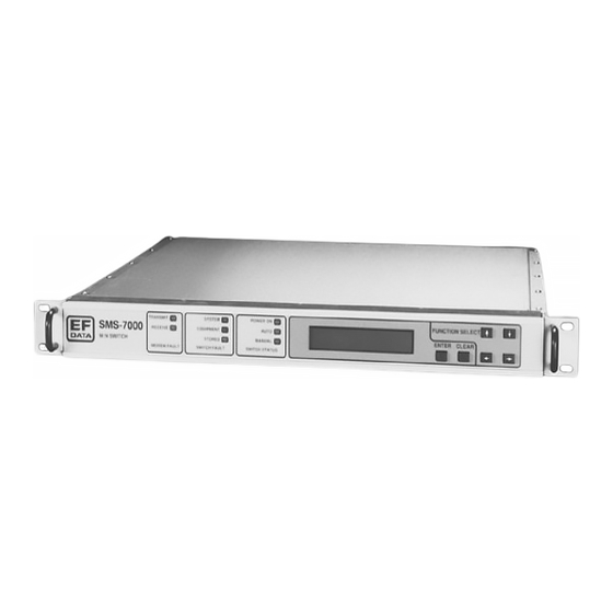
Each front panel menu screen has corresponding remote commands. The front panel display menus are designed to guide the operator through the configuration process. Note: Refer to the menu tables presented in this chapter for specific configuration information. Figure 3-1. SMS-7000 Front Panel View Rev. 3 3–1... -
Page 72: Backup Modems
Operation SMS-7000 Modem Protection Switch 3.1.1 Backup Modems The configuration of the backup modems (1 or 2) is usually performed first. Each backup is defined to switch either independently or dependently, as a function of RX or TX faults in the assigned prime modems. -
Page 73: Led Indicators
SMS-7000 Modem Protection Switch Operation 3.2.1 LED Indicators The eight LEDs on the front panel indicate the following (see Table 3-1): Table 3-1. LED Indicators Name Description Status Power On Green Indicates that power is applied to the switch. Auto Green Indicates the switch is automatically assigning backup modems. -
Page 74: Front Panel Controls
Operation SMS-7000 Modem Protection Switch 3.2.2 Front Panel Controls The switch is locally operated by using the front panel keypad, which consists of the following keys (see Table 3-2): Table 3-2. Front Panel Keypad Description [ENTER] This key is used to select a displayed function, or to execute a change to the configuration. -
Page 75: Menu System
SMS-7000 Modem Protection Switch Operation Menu System Refer to Figure 3-2 through Figure 3-12 to access and execute all functions. Use the main menu in Figure 3-2 as a quick reference for accessing the protection switch functions. Refer to Section 3.2 for further configuration details. - Page 76 Operation SMS-7000 Modem Protection Switch This page is intentionally left blank. 3–6 Rev. 3...
-
Page 77: Front Panel Menu
SMS-7000 Modem Protection Switch Operation Front Panel Menu SMS-7000 "TYPE" VER: 2.1.8 F U N C T I O N S E L E C T F U N C T I O N S E L E C T... -
Page 78: Figure 3-3. Configuration Backup 1 And 2 Menu
Operation SMS-7000 Modem Protection Switch SMS-7000 F U N C T I O N S E L E C T C O N F I G U R A T I O N VER: X.X.X C O N F I G U R A T I O N... -
Page 79: Configuration Backup 1 And 2 Menu
SMS-7000 Modem Protection Switch Operation 3.4.1 Configuration Backup 1 and 2 Menu Refer to Figure 3-3. BACKUP MODEM #n Set # other than 0. Numbers 9 or 10 are recommended when the ADDRESS protection system is full; two backups and eight prime modems. -
Page 80: Figure 3-4. Configuration Independent Prime 1 Through 8 Menu
Operation SMS-7000 Modem Protection Switch C O N F I G U R A T I O N SMS-7000 F U N C T I O N S E L E C T I N D E P E N D E N T VER: X.X.X... -
Page 81: Configuration Independent Prime 1 Through 8 Menu
SMS-7000 Modem Protection Switch Operation 3.4.2 Configuration Independent Prime 1 through 8 Menu Refer to Figure 3-4. PRIME MODEM #n Set # other than 0. Address 0 is a global address which is used to ADDRESS communicate with all modems even though the address is set to something else. - Page 82 Operation SMS-7000 Modem Protection Switch BREAKOUT #n Press [ENTER] to access submenus. CONFIGURATION D & I Use the BNC connectors for Unbalanced. Use the DB15 connector for Balanced. EXTERNAL CLOCK Use the BNC connectors for Unbalanced. Use the DB15 connector for Balanced...
- Page 83 SMS-7000 Modem Protection Switch Operation This page is intentionally left blank. Rev. 3 3–13...
-
Page 84: Figure 3-5. Configuration Dependent Prime 1 Through 8 Menu
Operation SMS-7000 Modem Protection Switch C O N F I G U R A T I O N S M S - 7 0 0 0 F U N C T I O N S E L E C T D E P E N D E N T VER: X.X.X... -
Page 85: Configuration Dependent Prime 1 Through 8 Menu
SMS-7000 Modem Protection Switch Operation 3.4.3 Configuration Dependent Prime 1 through 8 Menu Refer to Figure 3-5. PRIME MODEM #n Set # other than 0. Address 0 is a global address. ADDRESS Upon entry, the current status is displayed. Press [↑] or [ ↓] to make the selection. -
Page 86: Figure 3-6. Configuration Load/Verify Menu
Operation SMS-7000 Modem Protection Switch S M S - 7 0 0 0 F U N C T I O N S E L E C T C O N F I G U R A T I O N VER: X.X.X... -
Page 87: Configuration Load/Verify Menu
SMS-7000 Modem Protection Switch Operation 3.4.4 Configuration Load/Verify Menu Refer to Figure 3-6. LOAD PRIME MODEM n Active modems only (use if configuration changes have been made for any one prime modem). LOAD BACKUP MODEM n Active modems only (use if configuration changes have been made to all prime modems). -
Page 88: Figure 3-7. Configuration Operation Mode Menu
Operation SMS-7000 Modem Protection Switch S M S - 7 0 0 0 F U N C T I O N S E L E C T C O N F I G U R A T I O N VER: X.X.X... -
Page 89: Configuration Operation Mode Menu
SMS-7000 Modem Protection Switch Operation 3.4.5 Configuration Operation Mode Menu Refer to Figure 3-7. Operation Mode AUTO or MANUAL If ‘AUTO’, the Backup modem automatically replaces the failed Prime modems. If ‘MANUAL’, a submenu is enabled for direct control of the protection switch. The submenu displayed depends on the switching mode of the current backup modem;... -
Page 90: Figure 3-8. System Status Switching Menu
Operation SMS-7000 Modem Protection Switch SMS-7000 FUNCTION SELECT S Y S T E M S T A T U S VER: X.X.X S Y S T E M S T A T U S S W I T C H I N G... -
Page 91: System Status Switching Menu
SMS-7000 Modem Protection Switch Operation 3.4.6 System Status Switching Menu Refer to Figure 3-8. MOD mmmmmmmm Byxn Bzxn Status window. DMD dddddddd Byxn Bzxn Displays summary of active prime Mods and online backup Mods on Line 1. Displays summary of active prime Demods and online backup Demods on Line 2. -
Page 92: Figure 3-9. System Status Configuration Menu
Operation SMS-7000 Modem Protection Switch S M S - 7 0 0 0 F U N C T I O N S E L E C T S Y S T E M S T A T U S VER: X.X.X... -
Page 93: System Status Configuration Menu
SMS-7000 Modem Protection Switch Operation 3.4.7 System Status Configuration Menu Refer to Figure 3-9. One of the following four menus sequences will be displayed based on current backup modem switching modes: 1. Configuration: Backup #1 INDEPENDENT and Backup #2 INDEPENDENT 2. -
Page 94: Figure 3-10. Faults/Alarms Menu
Operation SMS-7000 Modem Protection Switch SMS-7000 FUNCTION SELECT VER: X.X.X FAULTS/ALARMS SYSTEM FAULTS TX OPERATIONAL RX OPERATIONAL BACKUP #n F A U L T S F A U L T S (n = 1 or 2) BK-UP MODEM COMM FAILURE... -
Page 95: Faults/Alarms Menu
SMS-7000 Modem Protection Switch Operation 3.4.8 Faults/Alarms Menu Refer to Figure 3-10. TX OPERATIONAL FAULTS n = prime modulators 1 to 8. If a number is present, the modulator is active, faulted, and not backed up. Fault indication clears when fault clears, or the primary is successfully backed up. -
Page 96: Figure 3-11. Stored Faults/Alarms Menu
Operation SMS-7000 Modem Protection Switch F U N C T I O N S E L E C T S M S - 7 0 0 0 S T O R E D VER: X.X.X F A U L T S / A L A R M S... -
Page 97: Stored Faults/Alarms Menu
SMS-7000 Modem Protection Switch Operation 3.4.9 Stored Faults/Alarms Menu Refer to Figure 3-11. TX OPERATIONAL FAULTS x x = Number of events (0 to 9), where 0 is oldest. Time and date HH:MM:SS MM/DD/YY displayed if fault is recorded, otherwise displays “NO FAULT.”... -
Page 98: Figure 3-12. Utility System Menu
Operation SMS-7000 Modem Protection Switch S M S - 7 0 0 0 F U N C T I O N S E L E C T UTILITY VER: X.X.X UTILITY S Y S T E M TIME: HH:MM:SS AM/PM... -
Page 99: Utility System Menu
SMS-7000 Modem Protection Switch Operation 3.4.10 Utility System Menu Refer to Figure 3-12. TIME: HH:MM:SS AM/PM Scroll left or right and press [↑] or [↓] to set, then press [ENTER]. DATE: MMDDYY REMOTE BAUD RATE This is the protocol set-up between the switch and an external terminal. -
Page 100: Setup And Configuration
Operation SMS-7000 Modem Protection Switch Setup and Configuration 3.5.1 Utility Setup Prior to configuration, it may be necessary to modify the following: • Display Contrast — Adjust for optimum viewing in local ambient lighting conditions. • Remote options — If a remote is to be used, appropriate remote options must be verified or defined from the Utility menus. -
Page 101: Prime
SMS-7000 Modem Protection Switch Operation 3.5.2.2 Prime The mode of the backup to which the prime is assigned (Independent or Dependent) determines the menu provided for the prime by the system. • Address — Enter a 3-digit decimal address for remote communications. -
Page 102: Operation Mode
Operation SMS-7000 Modem Protection Switch 3.5.2.4 Operation Mode Two modes of operation are available for the switch. • Auto — Automatically allows the Backup modem to replace any prime modem when a MOD or DEMOD failure occurs. • Manual — When Manual mode is selected, the system provides a dedicated menu through which the user may assign backup RX and TX functions to replace the prime modems. -
Page 103: Initial Defaults
SMS-7000 Modem Protection Switch Operation Initial Defaults Refer to Table 3-4 for initial defaults. Table 3-4. Initial Defaults Configuration Backup #n (n = 1 or 2) Backup Mod #n Backup #1 Multiplexer Backup Demod #n Backup #2 Mulitiplexer Backup #n Switching Mode... - Page 104 Operation SMS-7000 Modem Protection Switch This page is intentionally left blank. 3–34 Rev. 3...
-
Page 105: Chapter 4. Theory Of Operation
Chapter 4. THEORY OF OPERATION This chapter provides the theory of operation for the switch and explains various interfaces and switching modes. Interfaces 4.1.1 Configuration The configuration interfaces (J1 and J2) are located on the rear panel of the SCU (refer to Figure 4-1). -
Page 106: Figure 4-1. If Switch Block Diagram
Theory of Operation SMS-7000 Modem Protection Switch Figure 4-1. IF Switch Block Diagram 4–2 Rev. 3... -
Page 107: Terrestrial Data
SMS-7000 Modem Protection Switch Theory of Operation 4.1.2 Terrestrial Data All terrestrial data connections are provided on the face of the DSU. Each plug-in Data Switch Module (DSM) contains a built-in breakout panel that supports a variety of standard data and alarm interfaces (refer to Table 4-1). These interfaces can support IBS, IDR, D&I, or custom formats. -
Page 108: Monitors
Theory of Operation SMS-7000 Modem Protection Switch 4.1.4 Monitors Three connectors provide switch status and fault information on the rear of the SCU chassis (refer to Table 4-2). Table 4-2. SCU Chassis Connectors Switch Faults System, Equipment, and Stored Faults... -
Page 109: Modem Interfaces
SMS-7000 Modem Protection Switch Theory of Operation 4.1.5 Modem Interfaces Connectors on the modem side of the DSU and IFU chassis provide direct pin-for-pin data connections to the applicable Comtech EFData modems. A connector on the rear of the SCU provides remote and switch control of the modems associated with the switch. -
Page 110: Switching Modes
Theory of Operation SMS-7000 Modem Protection Switch Switching Modes Three distinct modem configurations facilitate the function of both independent and dependent backup configurations: • Dependent RX/TX — Both RX and TX functions are switched regardless of RX or TX prime fault. - Page 111 SMS-7000 Modem Protection Switch Theory of Operation The prime modem with the lowest channel slot will have a backup modem in hot standby if all of the priorities are set to the same level. This does not mean that it is a firm priority level, it simply means that if no priorities are selected, then the switch must place the backup modem in standby for one of the modems.
- Page 112 Theory of Operation SMS-7000 Modem Protection Switch This page is intentionally left blank. 4–8 Rev. 3...
-
Page 113: Chapter 5. Maintenance
Chapter 5. MAINTENANCE This chapter provides maintenance and troubleshooting information. Periodic Maintenance There is no periodic maintenance required to ensure proper switch operation. Software Revisions Installation of revised controller software may be necessary at times for implementing additions or enhancing features and/or corrective actions. Control software resides in a programmable device inside the one unit (1U) switch control chassis (AS/4800). -
Page 114: Fault Action
Maintenance SMS-7000 Modem Protection Switch 5. Replace cover and fasteners. 6. Install and interconnect switch controller in rack. 7. Reconnect power to switch. 8. Perform a hard reset under the Utility/System menu. 9. Enter desired switch configuration. 10. Load all modems from Load/Verify menu or remote terminal. -
Page 115: Switch
SMS-7000 Modem Protection Switch Maintenance 3. Replace the faulted modem with a properly functioning modem. Power up the replacement modem, and configure the modem exactly as the faulted modem was configured. 4. On the switch, turn on the modulator and demodulator for the modem that has been replaced. - Page 116 Maintenance SMS-7000 Modem Protection Switch Table 5-1. Switch Fault Analysis (Continued) Fault Description Action NO MOD CONFIG LOADED No configuration for modulators in Reload modem configuration from memory. Load/Verify menu. NO DMOD CONFIG LOADED No configuration for modulators in Reload modem configuration from memory.
-
Page 117: Appendix A. Remote Control Operation
Appendix A. REMOTE CONTROL OPERATION This appendix describes the remote control operation of the switch. • Firmware number: FW/4958-1J • Software version: 2.1.8 General The remote controls and status for the switch are based on the SMS-658 and SMS-758 redundancy switches to facilitate the use of existing control code to the extent possible. Due to unique and advanced features of the switch, there are differences, additions, and deletions from the former command set. -
Page 118: Table A-1. Sms-7000 Remote Control: Sms-658/Sms-758 Comparison Table
Remote Control Operation SMS-7000 Modem Protection Switch Table A-1. SMS-7000 Remote Control: SMS-658/SMS-758 Comparison Table Command SMS-7000 SMS-658 SMS-758 Notes Backup Modem Address ADD_Bx_yyy ADD_Bx_yyy ADD_Bx_yyy Backup Mod Active MA_Bx_yyy MA_Bx_yyy MA_Bx_yyy Backup Demod Active DA_Bx_yyy DA_Bx_yyy DA_Bx_yyy Switching Mode Selection... -
Page 119: Message Structure
SMS-7000 Modem Protection Switch Remote Control Operation Table A-1. SMS-7000 Remote Control: SMS-658/SMS-758 Comparison Table (Continued) Command SMS-7000 SMS-658 SMS-758 Notes TX Operational Stored Faults TOSF_# SMS-7000 only RX Operational Stored Faults ROSF_# SMS-7000 only Backup Modem System Stored Faults... -
Page 120: Start Characters
Remote Control Operation SMS-7000 Modem Protection Switch A.2.1 Start Characters A single character precedes all messages transmitted on the remote link. This character flags the start of a message, as follows: • “<” for commands • “>” for switch responses, or “>>” for modem responses through the switch.A.2.2 Device Address... -
Page 121: End Character
SMS-7000 Modem Protection Switch Remote Control Operation Notes: “add” is used to indicate a valid 1 to 3 character device address in the range between 1 and 255. 2. The switch does not respond to erred communications (i.e., parity and framing errors). -
Page 122: Configuration Commands/Responses
Remote Control Operation SMS-7000 Modem Protection Switch Configuration Commands/Responses A.3.1 Backup Modem Backup Command: <add/ADD_Bx_yyy'cr' Where: Modem Response: >add/ADD_Bx_yyy'cr''lf'] Address x = 1 or 2 (backup modem number). Status: <add/ADD_Bx_'cr' Response: >add/ADD_Bx_yyy'cr''lf'] yyy = 0 to 255 (backup modem address; 0 places backup modem out of service). -
Page 123: Prime Modem
SMS-7000 Modem Protection Switch Remote Control Operation Backup Command: <add/MUA_Bx_yyy'cr' Where: Multiplexer Response: >add/MUA_Bx_yyy'cr''lf'] Unit Address x = 1 or 2 (backup multiplexer number). Status: <add/MUA_Bx'cr' Response: >add/MUA_Bx_yyy'cr''lf'] yyy = 0 to 255 (backup multiplexer address; 0 places backup multiplexer out of service). -
Page 124: Switch
Remote Control Operation SMS-7000 Modem Protection Switch Prime Command: <add/DD_x_yyy.y'cr' Where: Demodulato Response: >add/DD_x_yyy.y'cr''lf'] r On-line x = 1 to 8 (prime modem demodulator number). Delay Status: <add/DD_x'cr' Response: >add/DD_x_yyy.y'cr''lf'] NONE, AUTO, or MANUAL. yyy.y = 0.5 to 127.0 seconds (in 0.5 second increments). -
Page 125: Breakout
<add/REM_'cr' Notes: Operation Response: >add/REM_'cr''lf'] 1. Configures the SMS-7000 for remote operation. 2. The SMS-7000 will respond to any status request at any time. However, the SMS-7000 must be in Remote mode to change configuration parameters remotely. Clear Command: <add/CLSF_'cr'... -
Page 126: Mode
1. This command selects the mode of operation for the Response: >add/MODE_xxxxxx'cr''lf'] SMS-7000. 2. If AUTO is selected, the M&C in the SMS-7000 controls all switching decisions. 3. If MANUAL is selected, the operator controls all switching decisions via the following three commands. -
Page 127: Status Commands/Responses
(See Note) Multiplexer Unit Address The backup modulator configuration status command causes a block of data to be returned by the SMS-7000. The block of data reflects the stored configuration of the backup modem selected. Note: Status only returned if multiplexer unit attached. - Page 128 External Clock (BAL/UNBAL) IDI_xxxx'cr''lf'] Insert Data Input (LOOP/NORM) The prime demodulator configuration status command causes a block of data to be returned by the SMS-7000. The block of data reflects the stored configuration of the prime modem selected. Notes: 1. Status only returned in Independent Mode.
- Page 129 SMS-7000 Modem Protection Switch Remote Control Operation Backup Command: <add/MFS_Bn'cr' Where: n = 1 or 2 (backup modem number). Modem Response: >add/MFS_Bn'cr' Fault Status MOD_xxx'cr' Modulator Status (OK/FLT) Summary DMD_xxx'cr''lf'] Demodulator Status (OK/FLT) Prime Command: <add/MFS_n'cr' Where: n = 1 to 8 (prime modem number).
- Page 130 Remote Control Operation SMS-7000 Modem Protection Switch Equipment Command: <add/EFS_'cr' Fault Status Response: >add/EFS_'cr' Summary DATA_MODULE_1_xxx'cr' Data Switch Module #1 (OK/FLT) DATA_MODULE_2_xxx'cr' Data Switch Module #2 (OK/FLT) DATA_MODULE_3_xxx'cr' Data Switch Module #3 (OK/FLT) DATA_MODULE_4_xxx'cr' Data Switch Module #4 (OK/FLT) DATA_MODULE_5_xxx'cr'...
- Page 131 SMS-7000 Modem Protection Switch Remote Control Operation Character 'c': Demodulator fault status character 1. Bit 6 = 1 always. Bit 5 = Prime demodulator #1 fault. Bit 4 = Prime demodulator #2 fault. Bit 3 = Prime demodulator #3 fault.
- Page 132 Remote Control Operation SMS-7000 Modem Protection Switch Bit 1 = Reserved. Bit 0 = Reserved. Character 'k': Backup #1 system fault status character 3. Bit 6 = 1 always. Bit 5 = Reserved. Bit 4 = Reserved. Bit 3 through Bit 0 = Binary representation (0 through 10) of the number of Backup #1 system stored faults.
- Page 133 SMS-7000 Modem Protection Switch Remote Control Operation Bit 0 = No prime demodulator configuration loaded fault. Character 's': Prime #2 system fault status character 2. Bit 6 = 1 always. Bit 5 = Prime not assigned to backup fault. Bit 4 = Prime multiplexer communications failure fault.
- Page 134 Remote Control Operation SMS-7000 Modem Protection Switch Character 'aa': Prime #5 system fault status character 1. Bit 6 = 1 always. Bit 5 = Prime modem communications failure fault. Bit 4 = Prime modulator configuration verify error fault. Bit 3 = Prime demodulator configuration verify error fault.
- Page 135 SMS-7000 Modem Protection Switch Remote Control Operation Bit 0 = Reserved. Character 'ai': Prime #7 system fault status character 3. Bit 6 = 1 always. Bit 5 = Reserved. Bit 4 = Reserved. Bit 3 through Bit 0 = Binary representation (0 through 10) of the number of Prime #7 system stored faults.
-
Page 136: Stored Faults
Remote Control Operation SMS-7000 Modem Protection Switch Stored Faults Information on stored faults is returned when requested. If no stored fault exists for a given fault number, the words “NO Fault” will be returned instead of the normal time/date status information. -
Page 137: About Switch
SMS-7000 Modem Protection Switch Remote Control Operation Prime Command: <add/SSF_n_#'cr' Where: n = 1 to 8 (prime modem number). Modem Response: >add/SSF_n_# hh:mm:ss System MM/DD/YY'cr' Modem Communications (OK/FLT) Stored COMM_xxx'cr' Modulator Config Verify (OK/FLT) Faults MOD_CONFIG_VFY_xxx'cr' Demodulator Config Verify (OK/FLT) - Page 138 Remote Control Operation SMS-7000 Modem Protection Switch Data Switch Command: <add/DMFI_'cr' Where: Module Response: >add/DMFI_'cr' nnnnnn = Firmware number (0 to 99999). Firmware DM1_FW/nnnnnn-zzr,mm/dd/yy'cr' zz = Firmware dash number (0 to 99). Information or DM1_xxx'cr' r = Firmware revision (-, or A to Z).
-
Page 139: Appendix B. M-2000 Multiplexer Utilization
Appendix B. M-2000 MULTIPLEXER UTILIZATION Appendix C describes the installation and operation of the switch when equipped with the M-2000 multiplexer (hereafter referred to as the “MUX”). Installation The switch M&C must have firmware #FW4958-1B, Version 2.1.1 or greater. This equipment contains parts and assemblies sensitive to damage by Electrostatic Discharge (ESD). -
Page 140: Figure B-1. Terrestrial Data Interconnections
M-2000-Multiplexer Utilization SMS-7000 Modem Protection Switch Figure B-1. Terrestrial Data Interconnections Refer to Table B-1 for signal pinout information on the data switch module J6 connector equipped with a MUX. Note: The 8 kbit/s IDR overhead data channel can be directly connected to the prime multiplexer. -
Page 141: Operation
SMS-7000 Modem Protection Switch M-2000-Multiplexer Utilization Table B-1. SMS-7000/M-2000 50-Pin to 37-Pin Interface Cable Pinouts 50-Pin Signal Name 37-Pin Shield CH2 SDA CH2 SDB CH2 RDA CH2 RDB CH3 SDA CH3 SDB CH3 RDA CH3 RDB CH4 SDA CH4 SDB... - Page 142 M-2000-Multiplexer Utilization SMS-7000 Modem Protection Switch This page is intentionally left blank. B–4 Rev. 3...
- Page 143 Glossary The following is a list of acronyms and abbreviations that may be found in this manual: Acronym/ Definition Abbreviation ADPCM Adaptive Differential Pulse Code Modulation ASCII American Standard Code for Information Interchange ASGN Assign ASYNC Asynchronous AUTO Automatic BCKUP Backup Break Out Panel Backup...
- Page 144 Glossary SMS-7000 Modem Protection Switch Input/Output INTELSAT Business Services Insert Data In Insert Data Out Intermediate Data Rate Intermediate Frequency Intermediate Frequency Switch Unit Independent Liquid Crystal Display Light-Emitting Diode M&C Monitor and Control Megahertz (10 Hertz) Modulator Normally Closed...
- Page 145 Index About Switch, A–21 Load/Verify, 3–16, 3–17, 3–31, 5–2, 5–3, 5–4 ADPCM Audio Data (J5), 2–32 Manual Mode, 4–6 Alarms (J2), 2–31 Menu System, 3–5 Auto Mode, 4–6 Message Structure, A–3 Back Mount, 2–7 Mode, 3–18, 3–19, 3–30, 3–32, A–2, A–6, A–10, A–11, Backup Modem, 3–2, A–2, A–3, A–6, A–8, A–10, A–13, A–12 A–20...
- Page 146 Index SMS-7000 Modem Protection Switch Terrestrial Data, 1–13, 2–26, 2–27, 2–28, 2–29, 4–3 Unbalanced Data Ports, 2–34 THEORY OF OPERATION, 4–1 Unpacking, 2–1 Top Mount, 2–7, 2–9 User Interfaces, 2–22 User Remote (J1), 2–22 Utility Setup, 3–30 i–2 Rev. 3...
-
Page 147: Metric Conversions
METRIC CONVERSIONS Units of Length Unit Centimeter Inch Foot Yard Mile Meter Kilometer Millimeter 1 centimeter — 0.3937 0.03281 0.01094 6.214 x 10 0.01 — — 1 inch 2.540 — 0.08333 0.2778 1.578 x 10 0.254 — 25.4 1 foot 30.480 12.0 —... - Page 148 2114 85281 WEST TH STREET TEMPE ARIZONA 480 • 333 • 2200 PHONE 480 • 333 • 2161...
Need help?
Do you have a question about the SMS-7000 and is the answer not in the manual?
Questions and answers