Comtech EF Data CRS-170A Installation And Operation Manual
L-band 1:1 redundancy switch, accessory product for use only with comtech ef data cdm-625a, cdm-625, h64/h32/h16/h8 heights remote gateways, cdm-850, cdm-840, cdm-760, cdm-750, cdm-570al, cdm-570l, cdm-710gl, cdm-710, cdm-700, cdm-600l clm-9600l, and sdm-
Hide thumbs
Also See for CRS-170A:
- Installation and operation manual (154 pages) ,
- Installation and operation manual (148 pages)
Table of Contents
Advertisement
Quick Links
CRS-170A
L-Band 1:1 Redundancy Switch
Installation and Operation Manual
Accessory Product for use only with Comtech EF Data CDM-625A, CDM-625,
H64/H32/H16/H8 Heights Remote Gateways, CDM-850, CDM-840, CDM-760,
CDM-750, CDM-570AL, CDM-570L, CDM-710GL, CDM-710, CDM-700,
CDM-600L (CLM-9600L), and SDM-300L3 Modems
(Modem Firmware and Hardware Requirements Apply)
IMPORTANT NOTE: The information contained in this document supersedes all previously published
information regarding this product. Product specifications are subject to change without prior notice.
Part Number MN/CRS170A.IOM / CD-CRS170A
Revision 14
Advertisement
Table of Contents

Related Manuals for Comtech EF Data CRS-170A


Summary of Contents for Comtech EF Data CRS-170A
- Page 1 CRS-170A L-Band 1:1 Redundancy Switch Installation and Operation Manual Accessory Product for use only with Comtech EF Data CDM-625A, CDM-625, H64/H32/H16/H8 Heights Remote Gateways, CDM-850, CDM-840, CDM-760, CDM-750, CDM-570AL, CDM-570L, CDM-710GL, CDM-710, CDM-700, CDM-600L (CLM-9600L), and SDM-300L3 Modems (Modem Firmware and Hardware Requirements Apply) IMPORTANT NOTE: The information contained in this document supersedes all previously published information regarding this product.
- Page 3 (Modem Firmware and Hardware Requirements Apply) Part Number MN/CRS170A.IOM / CD-CRS170A Revision 14 Copyright © Comtech EF Data, 2017. All rights reserved. Printed in the USA. Comtech EF Data, 2114 West 7th Street, Tempe, Arizona 85281 USA, 480.333.2200, FAX: 480.333.2161...
- Page 4 BLANK PAGE...
-
Page 5: Table Of Contents
European Union RoHS Directive (2002/95/EC) ................xvii European Union Telecommunications Terminal Equipment Directive (91/263/EEC) ....xvii CE Mark ............................xvii Product Support ............................xvii Comtech EF Data Headquarters ......................xviii Warranty Policy ............................. xviii Limitations of Warranty ........................xviii Exclusive Remedies ..........................xix CHAPTER 1. - Page 6 1.3.2.3 Managed Switch or Router Modes for CDM-570L/AL WITH Optional IP Module or Packet Processor ..........................1–12 1.3.3 CRS-170A Operation with CDM-600L (CLM-9600L) and SDM-300L3 Modems ..... 1–15 1.3.3.1 Operation with CDM-600L (CLM-9600L) Modems and CRS-150 Switch ....1–15 1.3.3.2 Operation with SDM-300L3 Modems and SMS-301 Switch ........
- Page 7 CHAPTER 5. CABLES AND CONNECTIONS ..............5–1 Overview ............................. 5–1 Common CRS-170A 1:1 Redundancy Control / IF Interface Cabling Kits ......5–3 Cabling to the CDM-625A or CDM-625 .................. 5–5 5.3.1 CRS-170ACDM-625A or CDM-625 Control and IF Interface Connections Using Cabling Kit KT-0000160 ...........................
- Page 8 Router Mode (Requires Optional IP Packet Processor) .......... 5–18 5.3.2.3 PMSI Interface Example ....................5–20 Cabling to the Heights Remote Gateway (HRG) ..............5–21 CRS-170A HRG Control and IF Interface Connections Using Cabling Kit KT-0000160 ..5.4.1 ............................... 5–21 5.4.1.1 Unit-to-Switch Control Interface Connection ...............
- Page 9 CRS-170A L-Band 1:1 Redundancy Switch MN/CRS170A.IOM / CD-CRS170A Table of Contents Revision 14 CRS-170A CDM-710GL Control and IF Interface Connections Using Cabling Kit 5.9.1 KT/12551 ............................5–53 5.9.1.1 Modem-to-Switch Control Interface Connection ............5–54 5.9.1.2 Modem-to-Switch IF Interface Connection ..............5–55 5.9.2...
- Page 10 Table 3-3. J4 | Control B Modem Connector Pinouts ................3–5 Table 3-4. J7 | Rx and J8 | Tx ‘Type ‘N’ Connectors ................3–6 Table 4-1. CRS-170A “Mode” DIP Switches – Product Compatibility Settings ........4–20 Table 4-2. CRS-170A “Switch Control” DIP Switches – Functional Settings ........4–20 FIGURES Figure 1-1.
- Page 11 Figure 3-3. CRS-170A – Modem Side Connectors .................. 3–4 Figure 3-4. CRS-170A – Antenna Side Connectors and Ground Stud (Rev. A and Later Versions) ..3–6 Figure 4-1. Heights Remote Gateway HTTP Interface ‘Utility’ Page Example (Page Banner, VFP NOT SHOWN) ............................
- Page 12 CRS-170A L-Band 1:1 Redundancy Switch MN/CRS170A.IOM / CD-CRS170A Table of Contents Revision 14 Figure 5-28. CDM-840 Unit-to-Switch Control Connections ..............5–34 Figure 5-29. CDM-840 Unit-to-Switch L-Band IF Connections ............5–35 Figure 5-30. CDM-840 Block Diagram – Gigabit Ethernet 1:1 Operation ..........5–36 Figure 5-31.
- Page 13 CRS-170A L-Band 1:1 Redundancy Switch MN/CRS170A.IOM / CD-CRS170A Table of Contents Revision 14 Figure A-12. Quad E1 User Data ‘Y’ Splitter Adapter Cable (CA-0000164) ........A-16 Figure A-13. Quad E1 User Data ‘Y’ Splitter Adapter Cable Kit (KT-0000122) ........A-17 Figure A-14.
- Page 14 CRS-170A L-Band 1:1 Redundancy Switch MN/CRS170A.IOM / CD-CRS170A Table of Contents Revision 14 BLANK PAGE...
-
Page 15: Preface
PREFACE About this Manual This manual provides installation and operation information for the Comtech EF Data CRS-170A L-Band 1:1 Redundancy Switch. This document is intended for anyone who installs or operates the CRS-170A in a 1:1 redundant system. Related Documents •... -
Page 16: Conventions And References
Patents and Trademarks See all of Comtech EF Data's Patents and Patents Pending at http://patents.comtechefdata.com. Comtech EF Data acknowledges that all trademarks are the property of the trademark owners. Warnings, Cautions and Notes A WARNING INFORMS YOU ABOUT A POSSIBLE HAZARD THAT MAY CAUSE DEATH OR SERIOUS INJURY. -
Page 17: Safety And Compliance
Watts, and draws a maximum of 250 mA at +12 volts DC and 120 mA at -12 volts DC. The power supply current is, in all circumstances, supplied by either a single Comtech EF Data modem, or a pair of these modems. -
Page 18: European Union Radio Equipment And Telecommunications Terminal Equipment (R&Tte) Directive (1999/5/Ec) And En 301 489-1
CRS-170A L-Band 1:1 Redundancy Switch MN/CRS170A.IOM Preface Revision 14 South Korean Electromagnetic Compatibility Unofficial translation: Class A: EMC Registration is done on this equipment for business use only (Class A). Product seller and user should notice that this equipment is not for household use. -
Page 19: European Union Low Voltage Directive (Lvd) (2006/95/Ec)
In accordance with the European Union Telecommunications Terminal Equipment Directive 91/263/EEC, the unit should not be directly connected to the Public Telecommunications Network. CE Mark Comtech EF Data declares that the unit meets the necessary requirements for the CE Mark. Product Support For all product support, please call: +1.240.243.1880 +1.866.472.3963 (toll free USA) -
Page 20: Comtech Ef Data Headquarters
Comtech EF Data is responsible for the freight charges only for return of the equipment from the factory to the owner. Comtech EF Data will return the equipment by the same method (i.e., Air, Express, Surface) as the equipment was sent to Comtech EF Data. -
Page 21: Exclusive Remedies
The warranty does not cover damage or loss incurred in transportation of the product. The warranty does not cover replacement or repair necessitated by loss or damage from any cause beyond the control of Comtech EF Data Corporation, such as lightning or other natural and weather related events or wartime environments. - Page 22 CRS-170A L-Band 1:1 Redundancy Switch MN/CRS170A.IOM Preface Revision 14 Notes:...
-
Page 23: Chapter 1. Introduction
Comtech EF Data L-Band satellite modems in a 1:1 redundant (Online ‘A’ and Backup ‘B’) configuration. The CRS-170A is compatible for use with the Comtech EF Data modem listed in Table 1-1. This table also summarizes the CRS-170A 1:1 IF Switch applications, including requirements for supporting data switching hardware and software. -
Page 24: Table 1-1. Crs-170A Compatibility Summary
2) This switch and its paired modems use Type ‘N’ connectors for L-Band operation. 3) Firmware updates are free and may be downloaded from the Comtech EF Data web site (www.comtechefdata.com). If a modem does not meet the hardware requirements, contact Comtech EF Data Product Support –... -
Page 25: Physical Features
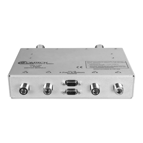
Physical Features 1.2.1 Modem Side Features Figure 1-2 shows the modem side of the CRS-170A. The connectors provided here facilitate all necessary external connections between the CRS-170A and the compatible Comtech EF Data modems. J6 TX B J5 TX A... -
Page 26: Top And Antenna Side Features
MN/CRS170A.IOM Introduction Revision 14 1.2.2 Top and Antenna Side Features Figure 1-3 shows the CRS-170A top and antenna side features and the chapters that provide more detailed information. Feature Description Chapter Section 4X #6-32 holes for vertical rack mounting (used with Switch Mounting Kit KT/11708) -
Page 27: Functional Description
1.3.1 Switch / Modem Operation The CRS-170A is configured with two modems to form a complete 1:1 redundant modem system. Within the CRS-170A, a redundancy controller continually monitors the status of faults for both modems to determine which modem should be Online and Offline. The control cables between the modems and the CRS-170A include four signal groups: •... - Page 28 Section 4.10 CRS-170A DIP Switch Settings Two green LEDs are located on the antenna side of the CRS-170A. They provide a visual identifier for the Online unit. With the ‘bridging’ architecture of the CRS-170A (whereby identical terrestrial data traffic signals are routed to both Online and Offline units), the redundancy controller can avoid unnecessary switchovers.
-
Page 29: 1:1 Ip Redundancy Data Switching
CRS-170A L-Band 1:1 Redundancy Switch MN/CRS170A.IOM Introduction Revision 14 will see that both faults have occurred at the same time (i.e., within a 0.5 second window), and infers that the fault is external. Therefore, no unnecessary switchover is initiated. 1.3.2 1:1 IP Redundancy Data Switching 1.3.2.1... -
Page 30: Cdm-710Gl, Cdm-710, Or Cdm-700
CRS-170A L-Band 1:1 Redundancy Switch MN/CRS170A.IOM Introduction Revision 14 Figure 1-4. 1:1 IP Redundancy Managed Switch Mode for CDM-625A or CDM-625, Heights Remote Gateway, Advanced VSAT CDM-850 or CDM-840, CDM-760, CDM-750, CDM-710GL, CDM-710, or CDM-700 Figure 1-4 shows a Managed Switch Mode 1:1 IP Redundancy setup with the Ethernet data interface of both modems connected to a Layer 2 Switch. - Page 31 CRS-170A L-Band 1:1 Redundancy Switch MN/CRS170A.IOM Introduction Revision 14 Figure 1-5. 1:1 IP Redundancy Managed Switch Mode – Switchover for CDM-625A or CDM-625, Heights Remote Gateway, Advanced VSAT CDM-850 or CDM-840, CDM-760, CDM-750, CDM-710GL, CDM-710, or CDM-700 Note the following: 1) The Managed Switch Mode method of redundancy is intended to be equivalent to pulling the Ethernet cable from one port and putting it into a different port on the same switch.
-
Page 32: Router Mode For Cdm-625A Or Cdm-625 With Optional Ip Packet Processor
CRS-170A L-Band 1:1 Redundancy Switch MN/CRS170A.IOM Introduction Revision 14 1.3.2.2 Router Mode For CDM-625A or CDM-625 WITH Optional IP Packet Processor All configuration changes can only be made to the Online unit and will require you to “Save Parameters to permanent storage” to ensure the configuration change is also applied to the Backup Modem. - Page 33 CRS-170A L-Band 1:1 Redundancy Switch MN/CRS170A.IOM Introduction Revision 14 Per Figure 1-7, the backup modem will also broadcast a “gratuitous ARP” which will tell all local devices to now associate a new MAC address for the Traffic IP 172.18.10.20. Each device will update their ARP tables and traffic will resume virtually instantaneously.
-
Page 34: Managed Switch Or Router Modes For Cdm-570L/Al With Optional Ip Module Or Packet Processor
CRS-170A L-Band 1:1 Redundancy Switch MN/CRS170A.IOM Introduction Revision 14 1.3.2.3 Managed Switch or Router Modes for CDM-570L/AL WITH Optional IP Module or Packet Processor • Do not use the M&C Ethernet port (bottom RJ-45 connector) when the optional IP Module is installed. - Page 35 CRS-170A L-Band 1:1 Redundancy Switch MN/CRS170A.IOM Introduction Revision 14 Figure 1-8. CDM-570L/AL 1:1 IP Redundancy Router Mode – ‘A’ Online 1–13...
- Page 36 CRS-170A L-Band 1:1 Redundancy Switch MN/CRS170A.IOM Introduction Revision 14 Figure 1-9. CDM-570L/AL 1:1 IP Redundancy Router Mode Switchover – ‘B’ Online 1–14...
-
Page 37: Crs-170A Operation With Cdm-600L (Clm-9600L) And Sdm-300L3 Modems
Similarly, the SDM-300L3 requires an SMS-301 switch together with the CRS-170A. In both cases, the CRS-170A is controlled by the supporting data switch, and places the ‘A’ or ‘B’ modem RF Online to match the data switch state. The CDM-600L (CLM-9600L) modems supply redundant power to the CRS-170A through the CRS-150. - Page 38 Interface. Additionally, the CRS-170A provides further isolation and security by using an RF relay within the unit. The Rx IF signal is fed to both modems simultaneously through the power divider in the CRS-170A. This divider introduces a loss of approximately 3.5 dB but, given the wide dynamic range of the demodulator in the CDM-600L (CLM-9600L), this is not considered to be a problem.
-
Page 39: Operation With Sdm-300L3 Modems And Sms-301 Switch
IF signals, 10MHz reference signals, DC power for the BUC and LNB, and FSK signaling to the BUC are switched in the CRS-170A under control of the SMS-301. In the case of equipment failure, automatic switching takes place to protect the traffic circuit. -
Page 40: Summary Of Specifications
CRS-170A L-Band 1:1 Redundancy Switch MN/CRS170A.IOM Introduction Revision 14 Summary of Specifications Equipment Type L-Band 1:1 Redundancy Switch Manufacturer Comtech EF Data, Tempe, Arizona Supported Comtech EF Data Modems CDM-625A or CDM-625 Advanced Satellite Modem with/without • optional IP Packet Processor H64/H32/H16/H8 Heights Remote Gateway •... - Page 41 CRS-170A L-Band 1:1 Redundancy Switch MN/CRS170A.IOM Introduction Revision 14 Weight 1.1lbs (0.5kg) Dimensions [excluding connectors] 1.7 H x 5.7 W x 4.1 D inches (43 H x 143 W x 104 D mm) Optional 19-inch rack mounting kit available.(CEFD P/N KT/11708)
- Page 42 CRS-170A L-Band 1:1 Redundancy Switch MN/CRS170A.IOM Introduction Revision 14 Notes: 1–20...
-
Page 43: Chapter 2. Installation
Chapter 2. INSTALLATION Unpack and Inspect the Shipment The CRS-170A L-Band 1:1 Redundancy Switch module and its optional Installation and Operation Manual (otherwise available online at http://www.comtechefdata.com) were packaged and shipped in a reusable cardboard carton containing protective foam spacing. -
Page 44: Mount The Unit
Revision 14 Mount the Unit The CRS-170A switch module’s small size and weight allow it to be freestanding. You may choose to let the module hang freely, supported only by the interfacing cables. Comtech EF Data KT/11708 Switch Mounting Kit... -
Page 45: Chapter 3. Switch Connectors And Pinouts
PINOUTS Cabling Connection Types The cable and connector types described in this section are commonly used in many Comtech EF Data products. Each cable type is typically dedicated to a specific mode of operation. The CRS-170A L-Band 1:1 Redundancy Switch and its compatible Traffic and Redundant Modems may not use all of these connector types. -
Page 46: Type 'Bnc
CRS-170A L-Band 1:1 Redundancy Switch MN/CRS170A.IOM Switch Connectors and Pinouts Revision 14 These connectors are available in two coupling styles: Bayonet or Threaded: • Bayonet Coupling Style – The jack has a pair of guideposts that accommodate the plug’s lockdown slots. This lockdown design provides secure assembly without over-tightening the connection. -
Page 47: D-Subminiature Cable Connections
CRS-170A L-Band 1:1 Redundancy Switch MN/CRS170A.IOM Switch Connectors and Pinouts Revision 14 3.1.2 D-Subminiature Cable Connections Type ‘D’ Connection Type Example Chassis Receptacles: (TOP) Female (BOTTOM) Male Type ‘D’ Cable With Jack Screws (Female Shown) Figure 3-2. D-Subminiature Connector Examples D-Subminiature connectors are also called Type ‘D’... -
Page 48: Crs-170A User Connectors
J4 Control B Figure 3-3. CRS-170A – Modem Side Connectors 3.2.1.1 IF Connectors (50Ω Type ‘N’) Four 50Ω Type ‘N’ female connectors are provided on the modem side of the CRS-170A. Table 3-1. Modem Side Type ‘Type ‘N’ Connectors Ref Des Name... -
Page 49: J3 | Control Connector (Top) - Modem 'A' (Db-9F)
CRS-170A L-Band 1:1 Redundancy Switch MN/CRS170A.IOM Switch Connectors and Pinouts Revision 14 3.2.1.2 J3 | Control Connector (Top) – Modem ‘A’ (DB-9F) The Modem ‘A’ Control connector is a 9-pin Type ‘D’ female interface. Pins 2, 3, and 4 carry signals looped through the switch module from Modem ‘B’ to Modem ‘A’, while pins 6, 7, and 8 loop the same signals from Modem ‘A’... -
Page 50: Antenna Side Connectors
See Section 1.3.1 in Chapter 1. INTRODUCTION and Section 4.10 in Chapter 4. MODEM • SWITCH CONFIGURATION for information about the “Switch Conditions” and “Intelligent / Dumb Controller” DIP switches. Figure 3-4. CRS-170A – Antenna Side Connectors and Ground Stud (Rev. A and Later Versions) 3.2.2.1 RF Connectors (50Ω Type ‘N’) Two 50Ω... - Page 51 SWITCH CONFIGURATION Overview To avoid damage either to the modem pair or the CRS-170A switch, it is important that you follow this sequence of configuration: • First, configure both modems for 1:1 redundant operation as directed in this chapter. This...
- Page 52 CRS-170A L-Band 1:1 Redundancy Switch MN/CRS170A.IOM Modem and Switch Configuration Revision 14 BLANK PAGE 4–2...
-
Page 53: Chapter 4. Modem And Switch Configuration
Interface Redundancy page. When both the traffic and backup modems are equipped with the optional IP Packet Processor and are connected to the CRS-170A L-Band 1:1 Redundancy Switch), there is no need to use the drop-down menu here, as Packet Processor Redundancy is enabled automatically. -
Page 54: For Cdm-625A Or Cdm-625S Equipped With The Optional Ip Packet Processor
CRS-170A L-Band 1:1 Redundancy Switch MN/CRS170A.IOM Modem and Switch Configuration Revision 14 4.2.1.2 For CDM-625A or CDM-625s Equipped With the Optional IP Packet Processor TO AVOID ETHERNET NETWORKING LOOPS – While in 1:1 Redundancy mode, with the optional IP Packet Processors enabled and both units operating in Managed Switch Mode, the Port 1 M&C Ethernet must be isolated from the Ethernet Traffic. -
Page 55: Heights Remote Gateways In 1:1 Redundancy
CRS-170A L-Band 1:1 Redundancy Switch MN/CRS170A.IOM Modem and Switch Configuration Revision 14 4.3 Heights Remote Gateways in 1:1 Redundancy Heights Networking Platform Spoke (Remote) Side Products Installation and Operation Manual (CEFD P/N MN-HEIGHTS-SPOKE) The H64, H32, H16, or H8 Heights Remote Gateway automatically detect connection to a 1:1 redundancy system. - Page 56 CRS-170A L-Band 1:1 Redundancy Switch MN/CRS170A.IOM Modem and Switch Configuration Revision 14 See Figure 4–2. If the unit is part of a 1:1 redundant pair and the unit is currently online, click [Force Redundancy Switch] to force this currently active unit to switch to standby mode.
-
Page 57: Advanced Vsat Cdm-850 Or Cdm-840 Operation In 1:1 Redundancy
CRS-170A L-Band 1:1 Redundancy Switch MN/CRS170A.IOM Modem and Switch Configuration Revision 14 Advanced VSAT CDM-850 or CDM-840 Operation in 1:1 Redundancy • CDM-850 Remote Router Installation and Operation Manual (CEFD P/N MN-CDM850) • CDM-840 Remote Router Installation and Operation Manual (CEFD P/N MN-CDM840) The Advanced VSAT CDM-850 and CDM-840 Remote Routers automatically detect connection to a 1:1 redundancy system. - Page 58 CRS-170A L-Band 1:1 Redundancy Switch MN/CRS170A.IOM Modem and Switch Configuration Revision 14 Notes: 4–8...
-
Page 59: Or Cdm-750 Operation In 1:1 Redundancy
CRS-170A L-Band 1:1 Redundancy Switch MN/CRS170A.IOM Modem and Switch Configuration Revision 14 CDM-760 or CDM-750 Operation in 1:1 Redundancy • CDM-760 Advanced High-Speed Trunking Modem Installation and Operation Manual (CEFD P/N MN-CDM760) • CDM-750 Advanced High-Speed Trunking Modem Installation and Operation Manual... - Page 60 CRS-170A L-Band 1:1 Redundancy Switch MN/CRS170A.IOM Modem and Switch Configuration Revision 14 Notes: 4–10...
-
Page 61: Configure The Cdm-570Ls Or Cdm-570Als For 1:1 Redundancy
CDM-570/CDM-570L/CDMR-570L Satellite Modem Installation and Operation Manual (CEFD P/N MN/CDM570L.IOM) • CDM-570A/CDM-570AL Satellite Modem Installation and Operation Manual (CEFD P/N MN-CDM570A) For correct operation of the CRS-170A, the CDM-570/A Satellite Modems must have the following installed: • CDM-570L Base Modem Firmware Version 1.6.7 (or higher) •... -
Page 62: Cdm-570L Or Cdm-570Al Non-Ip Redundancy Configuration
Processor is INSTALLED, you must also open the ‘Admin | Pap Save’ page and immediately click [Save PaP Parameters]. Connect all cables to the modems and the CRS-170A. This includes the control cable, IF cable and data ‘Y’cables. Chapter 5. CABLES AND CONNECTIONS... -
Page 63: Ip Redundancy Configuration
Use a Layer 2 switch (preferred) or hub to establish an Ethernet connection between the two modems. Before you connect the modems to the CRS-170A, you must first use the modem CLI to configure the following CDM-570L or CDM-570AL IP operation settings: •... - Page 64 CRS-170A L-Band 1:1 Redundancy Switch MN/CRS170A.IOM Modem and Switch Configuration Revision 14 Figure 4-5. CDM-570L or CDM-570AL CLI 1:1 Redundancy Configuration Screen 4–14...
-
Page 65: Configure The Cdm-710Gls, Cdm-710S, Or Cdm-700S For 1:1 Redundancy
(CEFD P/N MN/CDM710.IOM) CDM-700 Satellite Modem Installation and Operation Manual • (CEFD P/N MN/CDM700.IOM) For correct operation of the CRS-170A, the CDM-710GL, -710, and -700 modems must have the following installed: • For the CDM-710GL: o Firmware Version 5.1.1 (or higher) •... -
Page 66: Non-Ip Redundancy Configuration
Enable the redundancy state for both modems. From the modem front panel: CONFIG: AUX (Redundancy Mode) ENA/DIS – set to Enable. Connect all cables – including the control cable, IF cable and data cables – to the modems and the CRS-170A. Chapter 5. CABLES AND CONNECTIONS 4.7.2... -
Page 67: Cdm-600L (Clm-9600L) Operation In 1:1 Redundancy
• CRS-150 1:1 Redundancy Switch Installation and Operation Manual (CEFD P/N MN/CRS150.IOM) 1) Correct operation of the CRS-170A requires use of the CRS-150 1:1 Redundancy Switch. 2) While the CDM-600L (CLM-9600L) Open Network Satellite Modems require no unique 1:1 configuration settings, they must have the following installed: Firmware Version 1.1.4 (or higher) - Page 68 CRS-170A L-Band 1:1 Redundancy Switch MN/CRS170A.IOM Modem and Switch Configuration Revision 14 Notes: 4–18...
-
Page 69: Crs-170A Dip Switch Settings
Comtech EF Data’s expansion of compatible product required a change in the labeling on the Antenna Side (towards the BUC and LNB) of the CRS-170A L-Band 1:1 Redundancy Switch. Figure 4-6 shows the change to the ‘Mode’ DIP switch labeling between the original and current (i.e., Rev. ‘A’ and later) production versions of the CRS-170A. -
Page 70: Table 4-1. Crs-170A "Mode" Dip Switches - Product Compatibility Settings
CRS-170A L-Band 1:1 Redundancy Switch MN/CRS170A.IOM Modem and Switch Configuration Revision 14 Table 4-1. CRS-170A “Mode” DIP Switches – Product Compatibility Settings DIP Switch Product Left Switch Right Switch Setup CDM-625A or CDM-625 Heights Networking Platform Down H64/H32/H16/H8 Heights Remote Gateway... -
Page 71: Chapter 5. Cables And Connections
CONNECTIONS Overview When assembling a Comtech EF Data 1:1 Redundancy System, in addition to purchasing the modem pair (one Redundant Modem, one Traffic Modem), you must also purchase a redundancy kit tailored to that modem choice. Each kit provides the CRS-170A L-Band 1:1 Redundancy Switch module, plus all cables and components required for interconnection of the redundant configuration to various interfaces (i.e.,... - Page 72 CRS-170A L-Band 1:1 Redundancy Switch MN/CRS170A.IOM Cables and Connections Revision 14 • Section 5.7 Cabling the CDM-760 or CDM-750 • Section 5.8 Cabling the CDM-570AL or CDM-570L • Section 5.9 Cabling the CDM-710GL • Section 5.10 Cabling the CDM-710 •...
-
Page 73: Common Crs-170A 1:1 Redundancy Control / If Interface Cabling Kits
When assembling a Comtech EF Data 1:1 Redundancy System, in addition to purchasing the desired modem pair (one Traffic Modem, one Backup Modem), you must also purchase a CRS-170A 1:1 Redundancy Control/IF Interface Cabling Kit tailored to your modem choice. Each kit provides the CRS-170A L-Band 1:1 Redundancy Switch module and the control and IF cables required for connection of the switch to the modems in the 1:1 redundancy configuration. - Page 74 CRS-170A L-Band 1:1 Redundancy Switch MN/CRS170A.IOM Cables and Connections Revision 14 5.2.1 KT-0000160 Redundancy Control / IF Interface Cabling Kit (CDM-625A or CDM-625, Heights or Advanced VSAT Products, CDM- 760 or CDM-750) KT-0000160 1:1 Redundancy Control / IF Interface Cabling Kit CEFD Part No.
-
Page 75: Cabling To The Cdm-625A Or Cdm-625
5.2.1) for your control and L-Band Modem-to-Switch cabling connections. Figure 5-1, Figure 5-2, and Figure 5-3 show how to connect a pair of CDM-625A or CDM-625 modems together with the CRS-170A L-Band 1:1 Redundancy Switch module. The table included with each figure lists the items you will need from this kit for your initial setup. -
Page 76: Modem-To-Switch Control Interface Connection
1) Excluding modems, the KT-0000160 CRS-170A L-Band 1:1 Redundancy Kit (Section 5.2.1) provides all components shown in Figure 5-1. 2) When you connect the Control Interface cables between the CRS-170A and the modems, make sure that you securely fasten the screw locks on the Type ‘D’ connectors. This prevents accidental disconnection of the cables, particularly when you are removing and replacing a standby unit. -
Page 77: Modem-To-Switch If Interface Connection
IMPORTANT: The Tx IF from ‘MODEM A’ connects to the Tx IF port ‘J5 | Tx A’ on the CRS-170A; similarly, the Tx IF from ‘MODEM B’ connects to the Tx IF port ‘J6 | Tx B’ on the CRS-170A. The same logic applies for the Rx IF connections. It is important to note that failure to observe this requirement will result in system malfunction. -
Page 78: Modem-To-Switch L-Band Tx / 70/140 Mhz Rx If Interface Connection
CRS-170A L-Band 1:1 Redundancy Switch MN/CRS170A.IOM Cables and Connections Revision 14 5.3.1.2.2 Modem-to-Switch L-Band Tx / 70/140 MHz Rx IF Interface Connection If the Tx IF is L-Band and the Rx IF is 70/140MHz, additional items may be purchased for this option, as shown here in Figure 5-3. -
Page 79: Modem-To-User Data Interface Connections And Examples
CRS-170A L-Band 1:1 Redundancy Switch MN/CRS170A.IOM Cables and Connections Revision 14 5.3.2 Modem-to-User Data Interface Connections and Examples 5.3.2.1 Modem-to-User Non-IP Data Interface Connections and Examples The data cables and components identified in each of the examples that follow in this section must be purchased separately, as required. -
Page 80: Eia-422/232 Interface Example
CRS-170A L-Band 1:1 Redundancy Switch MN/CRS170A.IOM Cables and Connections Revision 14 5.3.2.1.1 EIA-422/232 Interface Example CEFD Part No. Description CA/RB10461-1 Cable – 1:1 ‘Y’ Splitter, (2X) DB-25M DB-25F Figure 5-5. CDM-625A or CDM-625 EIA-422/232 1:1 Example 5.3.2.1.2 HSSI Interface Example CEFD Part No. -
Page 81: Quad E1 Interface Example
2) If you desires three or four separate ports of E1 (i.e., Port 1 and Port 2 -or- Port 3 and Port 4), then optional adapter cables may be purchased from Comtech EF Data to adapt the G.703 Balanced and Auxiliary G.703 DB-9F single connector pairs to outgoing Quad E1 connector pairs as follows: Converts (1) 9-pin Type ‘D’... -
Page 82: Balanced Interface Example
CRS-170A L-Band 1:1 Redundancy Switch MN/CRS170A.IOM Cables and Connections Revision 14 5.3.2.1.4 G.703 Balanced Interface Example CEFD Part No. Description CA-0000071 Cable – 1:1 ‘Y’ Splitter, (2X) DB-9M DB-9F, 8” Figure 5-8. CDM-625A or CDM-625 G.703 Balanced 1:1 Example 5.3.2.1.5 G.703 Unbalanced Interface Example... -
Page 83: Asi Interface Example
CRS-170A L-Band 1:1 Redundancy Switch MN/CRS170A.IOM Cables and Connections Revision 14 5.3.2.1.6 ASI Interface Example KT/12579 ASI 75Ω Interface Kit CEFD Part No. Description CA/BNC75OHM Cable – IF BNC, 75Ω, 1’ RF/SA32KC-IN/OUT Combiner – 2-way w/Bracket, 0.25-300 MHz, 75Ω BNC Figure 5-10. -
Page 84: Engineering Service Channel (Esc) Interface Example
CRS-170A L-Band 1:1 Redundancy Switch MN/CRS170A.IOM Cables and Connections Revision 14 5.3.2.1.8 Engineering Service Channel (ESC) Interface Example CEFD Part No. Description CA-0000071 Cable – 1:1 ‘Y’ Splitter, (2X) DB-9M DB-9F, 8” Figure 5-12. CDM-625A or CDM-625 ESC 1:1 Example... -
Page 85: Modem-To-User Ip (10/100 Ethernet) Interface Examples
CRS-170A L-Band 1:1 Redundancy Switch MN/CRS170A.IOM Cables and Connections Revision 14 5.3.2.2 Modem-to-User IP (10/100 Ethernet) Interface Examples 5.3.2.2.1 Data Interface Connections Using IP Sub-Mux • Appendix N. IP SUB-MUX in CDM-625A Advanced Satellite Modem Installation and Operation Manual (CEFD P/N MN-CDM625A) •... - Page 86 CRS-170A L-Band 1:1 Redundancy Switch MN/CRS170A.IOM Cables and Connections Revision 14 Figure 5-13. CDM-625A or CDM-625 Block Diagram – 10/100 Ethernet 1:1 Managed Switch Mode 5–16...
- Page 87 CRS-170A L-Band 1:1 Redundancy Switch MN/CRS170A.IOM Cables and Connections Revision 14 Figure 5-14. CDM-625A or CDM-625 10/100 Ethernet 1:1 Cabling Example – Managed Switch Mode (with/without Dedicated Management Port) 5–17...
-
Page 88: Router Mode (Requires Optional Ip Packet Processor)
CRS-170A L-Band 1:1 Redundancy Switch MN/CRS170A.IOM Cables and Connections Revision 14 5.3.2.2.3 Router Mode (Requires Optional IP Packet Processor) • When the optional IP Packet Processor is installed and enabled, you should use Port 1 of each modem for M&C purposes only. Reserve use of Port 2, 3, or 4 for each modem for Ethernet traffic only. - Page 89 CRS-170A L-Band 1:1 Redundancy Switch MN/CRS170A.IOM Cables and Connections Revision 14 Figure 5-16. CDM-625A or CDM-625 10/100 Ethernet 1:1 Cabling Example – Router Mode 5–19...
-
Page 90: Pmsi Interface Example
Use of PMSI requires that you connect and secure the CDM-625A or CDM-625 Multi-drop CnC Plus 1:1 Cable CA-0000276 (2X DB-9M, 1’) between the Redundant Modem and the Traffic Modem using CnC. See Figure 5-17. The CA-0000276 Multi-Drop CnC PLUS 1:1 Cable bypasses the CRS-170A L-Band 1:1 Redundancy Switch. CEFD Part No. Description CDM-625A or CDM-625 Data Cable –... -
Page 91: Cabling To The Heights Remote Gateway (Hrg)
5.2.1) for your control and L-Band Unit-to-Switch cabling connections. Figure 5-18 and Figure 5-19 show how to connect a pair of HRGs together with the CRS-170A L-Band 1:1 Redundancy Switch module. The table included with each figure lists the items you will need from this kit for your initial setup. -
Page 92: Unit-To-Switch Control Interface Connection
1) The KT-0000160 CRS-170A L-Band 1:1 Redundancy Kit (Section 5.2.1) provides all components shown in Figure 5-18. 2) When you connect the Control Interface cables between the CRS-170A and the HRGs, make sure that you securely fasten the screw locks on the Type ‘D’ connectors. This prevents accidental disconnection of the cables, particularly when you are removing and replacing a standby unit. -
Page 93: Unit-To-Switch If Interface Connection
IMPORTANT: The Tx IF from ‘Unit A’ connects to the Tx IF port ‘J5 | Tx A’ on the CRS-170A; similarly, the Tx IF from ‘Unit B’ connects to the Tx IF port ‘J6 | Tx B’ on the CRS-170A. The same logic applies for the Rx IF connections. -
Page 94: Unit-To-User Data Interface Connections And Examples
CRS-170A L-Band 1:1 Redundancy Switch MN/CRS170A.IOM Cables and Connections Revision 14 5.4.2 Unit-to-User Data Interface Connections and Examples In addition to the control and IF Unit-to-Switch cabling shown previously, the HRG features an eight-port 10/100/1000 Gigabit Ethernet data interface. 5.4.2.1... - Page 95 CRS-170A L-Band 1:1 Redundancy Switch MN/CRS170A.IOM Cables and Connections Revision 14 Figure 5-21. HRG Gigabit Ethernet 1:1 Cabling Example (H64 Shown) – Managed Switch Mode 5–25...
-
Page 96: Hrg Router Mode
CRS-170A L-Band 1:1 Redundancy Switch MN/CRS170A.IOM Cables and Connections Revision 14 5.4.2.2 HRG Router Mode Figure 5-22 shows the block diagram and cabling example for an HRG 1:1 redundant configuration using the Gigabit Ethernet Interface in Router Mode. This configuration requires no cabling kit – you must use user-provided Ethernet cables and Layer 2 switch for direct connection to the modem via any one of the two, four, or eight available RJ-45 Traffic Ethernet ports. -
Page 97: Cabling To The Advanced Vsat Cdm-850
5.2.1) for your control and L-Band Unit-to-Switch cabling connections. Figure 5-23 and Figure 5-24 show how to connect a pair of CDM-850s together with the CRS-170A L-Band 1:1 Redundancy Switch module. The table included with each figure lists the items you will need from this kit for your initial setup. -
Page 98: Unit-To-Switch Control Interface Connection
1) Excluding the CDM-850s, the KT-0000160 CRS-170A L-Band 1:1 Redundancy Kit (Section 5.2.1) provides all components shown in Figure 5-23. 2) When you connect the Control Interface cables between the CRS-170A and the CDM-850s, make sure that you securely fasten the screw locks on the Type ‘D’... -
Page 99: Unit-To-Switch If Interface Connection
IMPORTANT: The Tx IF from ‘Unit A’ connects to the Tx IF port ‘J5 | Tx A’ on the CRS-170A; similarly, the Tx IF from ‘Unit B’ connects to the Tx IF port ‘J6 | Tx B’ on the CRS-170A. The same logic applies for the Rx IF connections. -
Page 100: Unit-To-User Data Interface Connections And Examples
CRS-170A L-Band 1:1 Redundancy Switch MN/CRS170A.IOM Cables and Connections Revision 14 5.5.2 Unit-to-User Data Interface Connections and Examples In addition to the control and IF Unit-to-Switch cabling shown previously, the CDM-850 features an eight-port 10/100/1000 Gigabit Ethernet data interface. 5.5.2.1... - Page 101 CRS-170A L-Band 1:1 Redundancy Switch MN/CRS170A.IOM Cables and Connections Revision 14 Figure 5-26. CDM-850 Gigabit Ethernet 1:1 Cabling Example – Managed Switch Mode 5–31...
-
Page 102: Router Mode
CRS-170A L-Band 1:1 Redundancy Switch MN/CRS170A.IOM Cables and Connections Revision 14 5.5.2.2 CDM-850 Router Mode Figure 5-27 shows the block diagram and cabling example for a CDM-850 1:1 redundant configuration using the Gigabit Ethernet Interface in Router Mode. This configuration requires no cabling kit – you must use user-provided Ethernet cables and Layer 2 switch for direct connection to the modem via any one of eight available RJ-45 Traffic Ethernet ports. -
Page 103: Cabling To The Advanced Vsat Cdm-840
5.2.1) for your control and L-Band Unit-to-Switch cabling connections. Figure 5-28 and Figure 5-29 show how to connect a pair of CDM-840s together with the CRS-170A L-Band 1:1 Redundancy Switch module. The table included with each figure lists the items you will need from this kit for your initial setup. -
Page 104: Unit-To-Switch Control Interface Connection
1) Excluding the CDM-840s, the KT-0000160 CRS-170A L-Band 1:1 Redundancy Kit (Section 5.2.1) provides all components shown in Figure 5-28. 2) When you connect the Control Interface cables between the CRS-170A and the CDM-840s, make sure that you securely fasten the screw locks on the Type ‘D’ connectors. -
Page 105: Unit-To-Switch If Interface Connection
IMPORTANT: The Tx IF from ‘Unit A’ connects to the Tx IF port ‘J5 | Tx A’ on the CRS-170A; similarly, the Tx IF from ‘Unit B’ connects to the Tx IF port ‘J6 | Tx B’ on the CRS-170A. The same logic applies for the Rx IF connections. -
Page 106: Gigabit Ethernet Data Interface Example
CRS-170A L-Band 1:1 Redundancy Switch MN/CRS170A.IOM Cables and Connections Revision 14 5.6.2 Unit-to-User Data Interface Connections and Examples In addition to the control and IF Unit-to-Switch cabling shown previously, the CDM-840 features a single 10/100/1000 Gigabit Ethernet RJ-45 data interface port, and a G.703 Unbalanced E1 data interface for use with the CDM-840’s optional E1 Interface/RAN Optimization Hardware/FAST Feature upgrade. - Page 107 CRS-170A L-Band 1:1 Redundancy Switch MN/CRS170A.IOM Cables and Connections Revision 14 5.6.2.2 KT/12542 G.703 75Ω Data Interface Kit (for G.703 Unbalanced E1) Figure 5-31 shows the block diagram and a cabling example for a CDM-840 1:1 configuration for the G.703 Unbalanced E1 data interface. You must use the KT/12542 interface kit with the CDM-840’s optional E1 Interface/RAN Optimization Hardware/FAST Feature upgrade.
-
Page 108: Block Diagram - G.703 Unbalanced E1 Data Interface Cabling To The Cdm-760 Or Cdm-750
CDM-760 or CDM-750 terrestrial data interface configuration and connection examples and details. You must use the Comtech EF Data KT-0000160 1:1 Redundancy Control/IF Interface Cabling Kit (Section 5.2.1) for your control and L-Band Unit-to-Switch cabling connections. See Section 5.7.1.1 for details about the CDM-760 or CDM-750 Modem-to-Switch Control Interface connection, and Section 5.7.1.2 for... -
Page 109: Modem-To-Switch Control Interface Connection
1) Excluding the modems, the KT-0000160 CRS-170A L-Band 1:1 Redundancy Kit (Section 5.2.1) provides all components shown in Figure 5-32. 2) When you connect the Control Interface cables between the CRS-170A and the modems, make sure that you securely fasten the screw locks on the Type ‘D’... -
Page 110: Modem-To-Switch If Interface Connection
IMPORTANT: The Tx IF from ‘MODEM A’ connects to the Tx IF port ‘J5 | Tx A’ on the CRS-170A; similarly, the Tx IF from ‘MODEM B’ connects to the Tx IF port ‘J6 | Tx B’ on the CRS-170A. The same logic applies for the Rx IF connections. It is important to note that failure to observe this requirement will result in system malfunction. -
Page 111: Modem-To-User Data Interface Connections And Examples
CRS-170A L-Band 1:1 Redundancy Switch MN/CRS170A.IOM Cables and Connections Revision 14 5.7.2 Modem-to-User Data Interface Connections and Examples In addition to the control and IF Modem-to-Switch cabling shown previously, a number of data interface configuration kits are available for use with the CDM-760 or CDM-750 High-Speed Trunking Modems. - Page 112 CRS-170A L-Band 1:1 Redundancy Switch MN/CRS170A.IOM Cables and Connections Revision 14 5.7.2.2 Optical Gigabit Ethernet Interface Option Example Figure 5-35 shows a CDM-760 or CDM-750 1:1 modem configuration that uses the FAST-activated ‘J7 | OPTICAL’ SFP port with the optional Optical Gigabit Ethernet Interface module (CEFD P/N IC-0000058).
- Page 113 CRS-170A L-Band 1:1 Redundancy Switch MN/CRS170A.IOM Cables and Connections Revision 14 5.7.2.3 Non-IP Data Interface Kit and Connection Examples While different data interface cards may be installed into both PIIC (Plug-In Interface Card) slots, only one data interface type is operable at a given time. The data...
- Page 114 CRS-170A L-Band 1:1 Redundancy Switch MN/CRS170A.IOM Cables and Connections Revision 14 5.7.2.3.1 KT/12542 G.703 75Ω Data Interface Kit (for Single G.703 E3/T3 PIIC) KT/12542 G.703 75Ω Interface Cabling Kit (for Single G.703 E3/T3 PIIC) CEFD Part No. Description CA/BNC75OHM Cable – IF, BNC 75Ω, 1’...
-
Page 115: Cabling To The Cdm-570Al Or Cdm-570L
CRS-170ACDM-570AL or CDM-570L Interface Connections Using 1:1 Redundancy Kit KT/10860-1 You must use the items provided in the Comtech EF Data KT/10860-1 1:1 Redundancy Kit for all possible CDM-570AL or CDM-570L data interface configurations: KT/10860-1 1:1 Redundancy Kit – Interface Cabling Reference (CRS-170A CDM-570AL or CDM-570L) Qty/Kit CEFD Part No. -
Page 116: Modem-To-Switch Control Interface Connection
1) Excluding the modems, the KT/10860-1 CRS-170A 1:1 Redundancy Kit (see Section 5.8.1) provides all components shown in Figure 5-38. 2) When you connect the Control Interface cables between the CRS-170A and the modems, make sure that you securely fasten the screw locks on the Type ‘D’... -
Page 117: Modem-To-Switch If Interface Connection
IMPORTANT: The Tx IF from ‘MODEM A’ connects to the Tx IF port ‘J5 | Tx A’ on the CRS-170A; similarly, the Tx IF from ‘MODEM B’ connects to the Tx IF port ‘J6 | Tx B’ on the CRS-170A. The same logic applies for the Rx IF connections. It is important to note that failure to observe this requirement will result in system malfunction. -
Page 118: Modem-To-User Data Interface Connections And Examples
CRS-170A L-Band 1:1 Redundancy Switch MN/CRS170A.IOM Cables and Connections Revision 14 5.8.1.3 Modem-to-User Data Interface Connections and Examples In addition to the control and IF Modem-to-Switch cabling shown previously, a number of data interface configurations are available for the CDM-570L or CDM-570AL or CDM-570L. -
Page 119: Eia-422/232 Interface Example
CRS-170A L-Band 1:1 Redundancy Switch MN/CRS170A.IOM Cables and Connections Revision 14 5.8.1.3.1.1 EIA-422/232 Interface Example CEFD Part No. Description CA/RB10461-1 Cable – 1:1 ‘Y’ Splitter, (2X) DB-25M DB -25F Figure 5-41. CDM-570L or CDM-570AL or CDM-570L EIA-422/232 1:1 Example 5.8.1.3.1.2 G.703 Balanced Interface Example CEFD Part No. -
Page 120: Unbalanced Interface Example
CRS-170A L-Band 1:1 Redundancy Switch MN/CRS170A.IOM Cables and Connections Revision 14 5.8.1.3.1.3 G.703 Unbalanced Interface Example G.703 Unbalanced 1:1 Interface Kit KT/10553-1 CEFD Part No. Description CA/BNC75OHM Cable – IF BNC, 1’ CN/BNC-TEE-JPJ T-Adapter, 50Ω BNC Figure 5-43. CDM-570AL or CDM-570L G.703 Unbalanced 1:1 Example... -
Page 121: Modem-To-User Ip (10/100 Ethernet) Interface Example
CRS-170A L-Band 1:1 Redundancy Switch MN/CRS170A.IOM Cables and Connections Revision 14 5.8.1.3.1.4 Modem-to-User IP (10/100 Ethernet) Interface Example Figure 5-44 shows the block diagram and cabling example for a CDM-570AL or CDM-570L 1:1 modem configuration using the IP (10/100 Ethernet) Interface. This configuration requires no cabling kit – you must use user-provided Ethernet cables and hub for direct connection to the ports. - Page 122 CRS-170A L-Band 1:1 Redundancy Switch MN/CRS170A.IOM Cables and Connections Revision 14 Notes: 5–52...
-
Page 123: Cabling To The Cdm-710Gl
CDM-710GL terrestrial data interface configuration and connection examples and details. You must use Comtech EF Data KT/12551 1:1 Redundancy Control/IF Interface Cabling Kit (Section 5.2.2) for your control and L-Band cabling connections. See Section 5.9.1.1 and Figure 5-45 for details about the CDM-710GL Modem-to-Switch Control Interface connections. -
Page 124: Modem-To-Switch Control Interface Connection
1) Excluding the modems, the KT/12551 CRS-170A L-Band 1:1 Redundancy Kit (Section 5.2.2) provides all components shown in Figure 5-45. 2) When you connect the Control Interface cables between the CRS-170A and the modems, make sure that you securely fasten the screw locks on the Type ‘D’... -
Page 125: Modem-To-Switch If Interface Connection
IMPORTANT: The Tx IF from ‘MODEM A’ connects to the Tx IF port ‘J5 | Tx A’ on the CRS-170A; similarly, the Tx IF from ‘MODEM B’ connects to the Tx IF port ‘J6 | Tx B’ on the CRS-170A. The same logic applies for the Rx IF connections. It is important to note that failure to observe this requirement will result in system malfunction. -
Page 126: Modem-To-User Data Interface Kit And Connection Examples
CRS-170A L-Band 1:1 Redundancy Switch MN/CRS170A.IOM Cables and Connections Revision 14 5.9.2 Modem-to-User Data Interface Kit and Connection Examples In addition to the basic Modem-to-Switch cabling shown previously, a number of data interface configuration kits are available for use with the CDM-710GL High-Speed Satellite Modem. Separate cabling kits are needed for these CDM-710GL data interfaces. -
Page 127: Single G.703 E3/T3/Sts-1 75Ω Data Interface (Cdi-10-1) Kit Kt/12583
CRS-170A L-Band 1:1 Redundancy Switch MN/CRS170A.IOM Cables and Connections Revision 14 5.9.2.1.1 Single G.703 E3/T3/STS-1 75Ω Data Interface (CDI-10-1) Kit KT/12583 Figure 5-48 shows an example for a CDM-710GL 1:1 modem configuration with the CDI-10-1 Single G.703 data interface installed in Slot 1, and with Slot 2 empty. The figure shows installation of one KT/12583 Single G.703 Interface Kit. -
Page 128: Hssi Data Interface (Cdi-60) Kit Kt/12586
CRS-170A L-Band 1:1 Redundancy Switch MN/CRS170A.IOM Cables and Connections Revision 14 5.9.2.1.2 HSSI Data Interface (CDI-60) Kit KT/12586 Figure 5-49 shows an example for a CDM-710GL 1:1 modem configuration with the CDI-60 HSSI data interface installed in Slot 1, and with Slot 2 empty. The figure shows installation of one KT/12586 HSSI Interface Kit. -
Page 129: Gigabit Ethernet Interface (Cdi-70) Example
Gigabit Ethernet Interface (CDI-70) Example See CEFD White Paper “Bridged Ethernet Interface Redundancy” available for download from Comtech EF Data’s Web site (www.comtechefdata.com). Figure 5-50 shows the block diagram and cabling example for a CDM-710GL 1:1 modem configuration with the CDI-70 Gigabit Ethernet data interface installed in Slot 2, with Slot 1 empty. This setup requires no cabling and component kit –... - Page 130 CRS-170A L-Band 1:1 Redundancy Switch MN/CRS170A.IOM Cables and Connections Revision 14 Notes: 5–60...
-
Page 131: Cabling To The Cdm-710
MN/CRS170A.IOM Cables and Connections Revision 14 5.10 Cabling to the CDM-710 1) For information on configuring the CRS-170A L-Band 1:1 Redundancy Switch with the CDM-710GL High-Speed Satellite Modems for 1:1 operation, see: • Chapter 4. MODEM SWITCH CONFIGURATION • CDM-710 Broadcast Satellite Modem Installation and Operation Manual (CEFD P/N MN/CDM710.IOM) -
Page 132: Modem-To-Switch Control Interface Connection
1) Excluding the modems, the KT/12551 CRS-170A L-Band 1:1 Redundancy Kit (Section 5.2.2) provides all components shown in Figure 5-51. 2) When you connect the Control Interface cables between the CRS-170A and the modems, make sure that you securely fasten the screw locks on the Type ‘D’... -
Page 133: Modem-To-Switch If Interface Connection
IMPORTANT: The Tx IF from ‘MODEM A’ connects to the Tx IF port ‘J5 | Tx A’ on the CRS-170A; similarly, the Tx IF from ‘MODEM B’ connects to the Tx IF port ‘J6 | Tx B’ on the CRS-170A. The same logic applies for the Rx IF connections. It is important to note that failure to observe this requirement will result in system malfunction. -
Page 134: Modem-To-User Data Interface Kit And Connection Examples
CRS-170A L-Band 1:1 Redundancy Switch MN/CRS170A.IOM Cables and Connections Revision 14 5.10.2 Modem-to-User Data Interface Kit and Connection Examples In addition to the basic Modem-to-Switch cabling shown previously, a number of data interface configuration kits are available for use with the CDM-710 Broadcast Satellite Modem. Separate cabling kits are needed for these data interfaces. -
Page 135: Asi 75Ω Data Interface (Cdi-40) Kit Kt/12579
CRS-170A L-Band 1:1 Redundancy Switch MN/CRS170A.IOM Cables and Connections Revision 14 5.10.2.1.1 ASI 75Ω Data Interface (CDI-40) Kit KT/12579 Figure 5-54 shows an example for a CDM-710 1:1 modem configuration with the CDI-40 ASI data interface installed in Slot 1, with Slot 2 empty. The figure shows installation of one KT/12579 ASI Interface Kit. -
Page 136: Hssi Data Interface (Cdi-60) Interface Kit Kt/12578
CRS-170A L-Band 1:1 Redundancy Switch MN/CRS170A.IOM Cables and Connections Revision 14 5.10.2.1.2 HSSI Data Interface (CDI-60) Interface Kit KT/12578 Figure 5-55 shows an example for a CDM-710 1:1 modem configuration with the CDI-60 HSSI data interface installed in Slot 1, with Slot 2 empty. The figure shows installation of one KT/12578 HSSI Interface Kit. -
Page 137: Gigabit Ethernet Data Interface (Cdi-70) Example
5.10.2.2 Gigabit Ethernet Data Interface (CDI-70) Example See CEFD White Paper “Bridged Ethernet Interface Redundancy” available for download from Comtech EF Data’s Web site (www.comtechefdata.com). Figure 5-50 shows the block diagram and cabling example for a CDM-710 1:1 modem configuration with the CDI-70 Gigabit Ethernet data interface installed in Slot 2, with Slot 1 empty. - Page 138 CRS-170A L-Band 1:1 Redundancy Switch MN/CRS170A.IOM Cables and Connections Revision 14 Notes: 5–68...
-
Page 139: Cabling To The Cdm-700
You must order terrestrial data interface components/kits separately. See Section 5.11.2 for CDM-700 terrestrial data interface configuration and connection examples and details. You must use the Comtech EF Data KT/12551 1:1 Redundancy Control/IF Interface Cabling Kit (Section 5.2.2) for your control and L-Band Unit-to-Switch cabling connections. See Section 5.11.1.1 and Figure 5-57 for the CDM-700 Modem-to-Switch Control Interface connection details. -
Page 140: Modem-To-Switch Control Interface Connection
1) Excluding the modems, the KT/12551 CRS-170A L-Band 1:1 Redundancy Kit (Section 5.2.2) provides all components shown in Figure 5-57. 2) When you connect the Control Interface cables between the CRS-170A and the modems, make sure that you securely fasten the screw locks on the Type ‘D’ connectors. This prevents accidental disconnection of the cables, particularly when you are removing and replacing a standby unit. -
Page 141: Modem-To-Switch If Interface Connection
IMPORTANT: The Tx IF from ‘MODEM A’ connects to the Tx IF port ‘J5 | Tx A’ on the CRS-170A; similarly, the Tx IF from ‘MODEM B’ connects to the Tx IF port ‘J6 | Tx B’ on the CRS-170A. The same logic applies for the Rx IF connections. It is important to note that failure to observe this requirement will result in system malfunction. -
Page 142: Modem-To-User Data Interface Kit And Connection Examples
CRS-170A L-Band 1:1 Redundancy Switch MN/CRS170A.IOM Cables and Connections Revision 14 5.11.2 Modem-to-User Data Interface Kit and Connection Examples In addition to the basic Modem-to-Switch cabling shown previously, a number of data interface configuration kits are available for use with the CDM-700 Satellite Modem. Separate cabling kits are needed for these data interfaces. -
Page 143: Dual G.703 E3/T3/Sts-1 75Ω Data Interface (Cdi-10) Kit Kt/12582 And Hssi Data Interface (Cdi-60) Kit Kt/12586
CRS-170A L-Band 1:1 Redundancy Switch MN/CRS170A.IOM Cables and Connections Revision 14 Figure 5-59 shows the block diagram typical for the kits shown in Sections 5.11.2.1.1 through 5.11.2.1.3. For example, Section 5.11.2.1.1 identifies the interface kit used with the CDI-10 Dual G.703 E3/T3/STS-1 and CDI-60 HSSI data interfaces. -
Page 144: 155Mb Copper Data Interface (Cdi-50) Kit Kt/12583
CRS-170A L-Band 1:1 Redundancy Switch MN/CRS170A.IOM Cables and Connections Revision 14 5.11.2.1.2 155MB Copper Data Interface (CDI-50) Kit KT/12583 Figure 5-61 shows an example for a CDM-700 1:1 modem configuration with a CDI-50 data interface installed in Slot 1 for use with 155MB Copper data, with Slot 2 empty. This figure shows installation of one KT/12583 155MB Copper Interface Kit –... -
Page 145: Data Interface (Cdi-50) Kits Kt/12585 (Single-Mode) Or Kt/12584 (Multi-Mode)
CRS-170A L-Band 1:1 Redundancy Switch MN/CRS170A.IOM Cables and Connections Revision 14 5.11.2.1.3 OC-3 Data Interface (CDI-50) Kits KT/12585 (Single-Mode) or KT/12584 (Multi-Mode) Figure 5-62 shows a CDM-700 1:1 modem configuration with installation of one CDI-50 data interface installed in Slot 1 for use with OC-3 data, with Slot 2 empty. This figure shows installation of one KT/12585 OC-3 Single-Mode Interface Kit. -
Page 146: Gigabit Ethernet Data Interface (Cdi-70) Example
5.11.2.2 Gigabit Ethernet Data Interface (CDI-70) Example See CEFD White Paper “Bridged Ethernet Interface Redundancy” available for download from Comtech EF Data’s Web site (www.comtechefdata.com). Figure 5-63 shows the block diagram and cabling example for a CDM-700 1:1 modem configuration with the CDI-70 Gigabit Ethernet data interface installed in Slot 1, with Slot 2 empty. -
Page 147: Cabling The Cdm-600L (Clm-9600L)
Figure 5-64 shows the block diagram for connecting a pair of CDM-600L (CLM-9600L) Open Network Satellite Modems together with the CRS-150 and CRS-170A switches. This figure also provides a table that identifies the cable assemblies that may be supplied with the CRS-170A in this configuration. - Page 148 CRS-170A L-Band 1:1 Redundancy Switch MN/CRS170A.IOM Cables and Connections Revision 14 Notes: 5–78...
-
Page 149: Cabling The Sdm-300L3
SMS-301 and CRS-170A switches. This figure also provides a table that identifies the cable assemblies that may be supplied with the CRS-170A in this configuration. The other cables between the SMS-301 and the SDM-300L3 are the same as are supplied with the SMS-301 in an SDM-300A application. - Page 150 CRS-170A L-Band 1:1 Redundancy Switch MN/CRS170A.IOM Cables and Connections Revision 14 Notes: 5–80...
-
Page 151: Appendix A. Cable Drawings
Appendix A. CABLE DRAWINGS Overview This appendix provides technical specification drawings for the cables used with the CRS-170A L-Band 1:1 Redundancy Switch. These cable details are grouped into two categories – Control Interface Cables (Section A.2), and IF/Data Interface Cables (Section A.3). -
Page 152: Control Interface Cables
CRS-170A L-Band 1:1 Redundancy Switch MN/CRS170A.IOM Appendix A Revision 14 Control Interface Cables App. A CABLE CEFD REF Ch. 5 DESCRIPTION USED FOR (TYPE) USED WITH CRS-170A CDM-625A, CDM-620 H64, H32, H16, or H8 Heights 5-18 Remote Gateway 1:1 Control CA/WR9378-4 Universal Cable, Control DB-9M ... -
Page 153: Switch-To-Modem, Universal Control Cable (Db-9MDb-9M
CRS-170A L-Band 1:1 Redundancy Switch MN/CRS170A.IOM Appendix A Revision 14 A.2.1 Switch-to-Modem, Universal Control Cable (DB-9MDB-9M) Alternate Cabling Note: CEFD Universal Control Cable CA/WR9378-8 (DB-9M DB-9M, 8’), sold separately, is available for use in place of CA/WR9378-4 Figure A-1. Universal Control Cable (CA/WR9378-4) -
Page 154: Switch-To-Modem, Adapter Control Cable, Rohs (Db-9MDb-15F
CRS-170A L-Band 1:1 Redundancy Switch MN/CRS170A.IOM Appendix A Revision 14 A.2.2 Switch-to-Modem, Adapter Control Cable, RoHS (DB-9MDB-15F) Figure A-2. Adapter Control Cable (CA/WR12135-1) -
Page 155: Switch-To-Modem, Optional 'Y' Splitter Adapter Control Cable ((2X) Db-9MDb-15F) A
CRS-170A L-Band 1:1 Redundancy Switch MN/CRS170A.IOM Appendix A Revision 14 A.2.3 Switch-to-Modem, Optional ‘Y’ Splitter Adapter Control Cable ((2X) DB-9MDB-15F) This cable permits user access to the Summary Fault Relay. You may purchase this optional CA/WR13011-4 ‘Y’ Splitter Adapter Control Cable as a replacement for the CA/WA12135-1 cable. -
Page 156: Switch-To-Modem, Optional Control Cable, Non-Muting (Db-9MDb-15F
CRS-170A L-Band 1:1 Redundancy Switch MN/CRS170A.IOM Appendix A Revision 14 A.2.4 Switch-to-Modem, Optional Control Cable, Non-muting (DB-9MDB-15F) This cable keeps the offline modem’s Tx IF-enabled. You may purchase this optional CA-0000187 Control Cable as a replacement for the CA/WA12135-1 cable. -
Page 157: Modem-To-Switch (Crs-170A And Crs-150), Data / Control 'Y' Cable (Db-25MDb-25M, Db-9M
CRS-170A L-Band 1:1 Redundancy Switch MN/CRS170A.IOM Appendix A Revision 14 A.2.5 Modem-to-Switch (CRS-170A and CRS-150), Data / Control ‘Y’ Cable (DB-25MDB-25M, DB-9M) Figure A-5. Data / Control ‘Y’ Cable (CA/WR10456-4) -
Page 158: Modem-To-Switch (Crs-170A And Sms-301), Control Cable (Db-9MDb-15M
CRS-170A L-Band 1:1 Redundancy Switch MN/CRS170A.IOM Appendix A Revision 14 A.2.6 Modem-to-Switch (CRS-170A and SMS-301), Control Cable (DB-9MDB-15M) Figure A-6. Control Cable (CA/WR10163-1) -
Page 159: If / Data Interface Cables
CRS-170A L-Band 1:1 Redundancy Switch MN/CRS170A.IOM Appendix A Revision 14 IF / Data Interface Cables App. A CABLE REF Ch. 5 DESCRIPTION USED FOR (TYPE) USED WITH CRS-170A CEFD P/N CDM-625A, CDM-625 H64, H32, H16, or H8 5-19 Heights Remote Gateway... - Page 160 CRS-170A L-Band 1:1 Redundancy Switch MN/CRS170A.IOM Appendix A Revision 14 App. A CABLE REF Ch. 5 DESCRIPTION USED FOR (TYPE) USED WITH CRS-170A CEFD P/N A-15 CA-0000276 Shielded Multi-drop CnC® Plus Cable, 1:1, DB-9M DB-9M, 1’ PMSI/CnC® Data Interface...
-
Page 161: Switch-To-Modem / Modem-To-User, L-Band Coaxial Cable, Rohs, Type 'N' 50Ω
CRS-170A L-Band 1:1 Redundancy Switch MN/CRS170A.IOM Appendix A Revision 14 A.3.1 Switch-to-Modem / Modem-to-User, L-Band Coaxial Cable, RoHS, Type ‘N’ 50Ω Figure A-7. Tx/Rx 50Ω Type ‘N’ Coaxial Cable (CA/RF10453-4) A-11... -
Page 162: Switch-To-Modem / Modem-To-User, 70/140 Mhz Coaxial Cable, Rohs, Type 'Bnc' 75Ω
CRS-170A L-Band 1:1 Redundancy Switch MN/CRS170A.IOM Appendix A Revision 14 A.3.2 Switch-to-Modem / Modem-to-User, 70/140 MHz Coaxial Cable, RoHS, Type ‘BNC’ 75Ω Figure A-8. Tx/Rx/User Data 75Ω Type ‘BNC’ Coaxial Cable (CA/BNC75OHM) A-12... -
Page 163: Modem-To-User, Splitter Cable (Db-25F(2X) Db-25M
CRS-170A L-Band 1:1 Redundancy Switch MN/CRS170A.IOM Appendix A Revision 14 A.3.3 Modem-to-User, Splitter Cable (DB-25F(2X) DB-25M) Figure A-9. 1:1 User Data Splitter Cable (CA/RB10461-1) A-13... -
Page 164: Modem-To-User, Cdm-625A, Cdm-625 Data 'Y' Splitter Cable (Db-9F(2X) Db-9M)
CRS-170A L-Band 1:1 Redundancy Switch MN/CRS170A.IOM Appendix A Revision 14 A.3.4 Modem-to-User, CDM-625A, CDM-625 Data ‘Y’ Splitter Cable (DB-9F(2X) DB-9M) Figure A-10. 1:1 User Data ‘Y’ Splitter Cable (CA-0000071) A-14... -
Page 165: Modem-To-User, Quad E1 'Y' Splitter Adapter Cable (Db-9M(2X) Db-15F
CRS-170A L-Band 1:1 Redundancy Switch MN/CRS170A.IOM Appendix A Revision 14 A.3.5 Modem-to-User, Quad E1 ‘Y’ Splitter Adapter Cable (DB-9M(2X) DB-15F) You may purchase this optional adapter cable to adapt the Balanced G.703 or Auxiliary G.703 DB-9F modem connections to a DB-15F connector pair. -
Page 166: Modem-To-User, Quad E1 'Y' Splitter Adapter Cable (Db-9M (2X) Rj-48F
CRS-170A L-Band 1:1 Redundancy Switch MN/CRS170A.IOM Appendix A Revision 14 A.3.6 Modem-to-User, Quad E1 ‘Y’ Splitter Adapter Cable (DB-9M (2X) RJ-48F) You may purchase this optional adapter cable to adapt the Balanced G.703 or Auxiliary G.703 DB-9F modem connections to a RJ-48F connector pair. -
Page 167: Modem-To-User, Quad E1 'Y' Splitter Adapter Cable Kit (Kt-0000122
CRS-170A L-Band 1:1 Redundancy Switch MN/CRS170A.IOM Appendix A Revision 14 A.3.7 Modem-to-User, Quad E1 ‘Y’ Splitter Adapter Cable Kit (KT-0000122) KT-0000122 Quad E1 Balanced/Unbalanced Adapter Kit CEFD PART NO. DESCRIPTION CA-0000347 ‘Y’ Cable Assy: DB-9M 2X RJ-48 Male 502-0532-001 Bolun Adapter, 2X RJ-48 Female ... -
Page 168: Modem-To-User, Overhead User Data 'Y' Splitter Cable (Hd-44F(2X) Hd-44M
CRS-170A L-Band 1:1 Redundancy Switch MN/CRS170A.IOM Appendix A Revision 14 A.3.8 Modem-to-User, Overhead User Data ‘Y’ Splitter Cable (HD-44F(2X) HD-44M) Figure A-14. Overhead User Data ‘Y’ Splitter Cable (CA-0000070) A-18... -
Page 169: Modem-To-Modem Cdm-625A, Cdm-625 Cnc Plus Shielded Multi-Drop Cable (Db-9MDb-9M
CRS-170A L-Band 1:1 Redundancy Switch MN/CRS170A.IOM Appendix A Revision 14 ® A.3.9 Modem-to-Modem CDM-625A, CDM-625 CnC Plus Shielded Multi-drop Cable (DB-9MDB-9M) Figure A-15. CDM-625A, CDM-625 CnC® Plus Shielded Multi-drop Cable (CA-0000276) A-19... -
Page 170: Modem-To-User, Rohs Optical Gigabit Ethernet Cable Assemblies, Single-Mode Or Multi-Mode ((2X) Type 'Lc'(4X) Type 'Lc
Revision 14 A.3.10 Modem-to-User, RoHS Optical Gigabit Ethernet Cable Assemblies, Single-Mode OR Multi-Mode ((2X) Type ‘LC’(4X) Type ‘LC’) See the table for the specific Comtech EF Data part number. CEFD PART NO. Description Comments Single-Mode ‘Y’ Cable Assy – RoHS-Compliant, Optical Coupler, 2m... -
Page 171: Modem-To-User, G.703 Balanced User Data 'Y' Splitter Cable (Db-15M(2X) Db-15M)
CRS-170A L-Band 1:1 Redundancy Switch MN/CRS170A.IOM Appendix A Revision 14 A.3.11 Modem-to-User, G.703 Balanced User Data ‘Y’ Splitter Cable (DB-15M(2X) DB-15M) Figure A-17. G.703 Balanced User Data ‘Y’ Splitter Cable (CA/WR10522-1) A-21... -
Page 172: Modem-To-User, Hssi User Data 'Y' Splitter Cable (Hd-50M(2X) Hd-50F
CRS-170A L-Band 1:1 Redundancy Switch MN/CRS170A.IOM Appendix A Revision 14 A.3.12 Modem-to-User, HSSI User Data ‘Y’ Splitter Cable (HD-50M(2X) HD-50F) Figure A-18. HSSI User Data ‘Y’ Splitter Cable (PP/SC3523) A-22... -
Page 173: Modem-To-User, Rohs Oc-3 Cable Assemblies, Single-Mode Or Multi-Mode (Type 'Sc/Upc'(2X) Type 'Sc/Upc
Revision 14 A.3.13 Modem-to-User, RoHS OC-3 Cable Assemblies, Single-Mode OR Multi-Mode (Type ‘SC/UPC’(2X) Type ‘SC/UPC’) See the table for the specific Comtech EF Data part number. CEFD PART NO. Description Comments Single-Mode ‘Y’ Cable Assy – RoHS-Compliant, Optical Coupler, 7’, Type ‘SC/UPC’... - Page 174 CRS-170A L-Band 1:1 Redundancy Switch MN/CRS170A.IOM Appendix A Revision 14 Notes A-24...
- Page 176 2114 85281 WEST TH STREET TEMPE ARIZONA 480 • 333 • 2200 PHONE 480 • 333 • 2161...
Need help?
Do you have a question about the CRS-170A and is the answer not in the manual?
Questions and answers