Comtech EF Data CRS-170A Installation And Operation Manual
L-band 1:1 redundancy switch
Hide thumbs
Also See for CRS-170A:
- Installation and operation manual (148 pages) ,
- Installation and operation manual (176 pages)
Table of Contents
Advertisement
Quick Links
CRS-170A
L-Band 1:1 Redundancy Switch
Installation and Operation Manual
Accessory Product for use only with Comtech EF Data
CDM-625, CDM-840, CDM-750, CDM-570L, CDM-700, CDM-710, CDM-710G,
CDM-600L (CLM-9600L), and SDM-300L3 Modems
(Modem Firmware and Hardware Requirements Apply)
IMPORTANT NOTE: The information contained in this document supersedes all previously published
information regarding this product. Product specifications are subject to change without prior notice.
Part Number MN/CRS170A.IOM
Revision 9
Advertisement
Table of Contents

Related Manuals for Comtech EF Data CRS-170A


Summary of Contents for Comtech EF Data CRS-170A
- Page 1 CRS-170A L-Band 1:1 Redundancy Switch Installation and Operation Manual Accessory Product for use only with Comtech EF Data CDM-625, CDM-840, CDM-750, CDM-570L, CDM-700, CDM-710, CDM-710G, CDM-600L (CLM-9600L), and SDM-300L3 Modems (Modem Firmware and Hardware Requirements Apply) IMPORTANT NOTE: The information contained in this document supersedes all previously published information regarding this product.
- Page 3 Errata A for MN/CRS170A.IOM Rev 9 Ch 4 Cabling ‐ Add CDM‐625 V.35 Data Interface Errata A Comtech EF Data Documentation Update Subject: Update IP Module HDLC/SLE FW Versioning Original Manual Part Number/Rev: MN/CDM570L Rev 12 Errata Number/ PLM Document ID: ER‐CRS170A‐EA9 PLM CO Number: C‐0026255 Comments: The updated information will be incorporated into the next formal revision of the manual: Revise Chapter 4. CABLES AND CONNECTIONS, page 4‐8: Update Sect. 4.2.4.1 title and Figure 4‐5 label to include V.35 Data Interface callout as shown here. ...
- Page 4 Errata A for MN/CRS170A.IOM Rev 9 Ch 4 Cabling ‐ Add CDM‐625 V.35 Data Interface This page is intentionally blank. ER-CRS170A-EA9 THIS DOCUMENT IS NOT SUBJECT TO REVISION/UPDATE! PLM CO C-0026255 Page 2 of 2...
- Page 5 Errata B Comtech EF Data Documentation Update Original Manual Part Number/Rev: MN/CRS170A.IOM Rev 9 Errata Number/ PLM Document ID: ER-CRS170A-EB9 PLM CO Number: C‐0027990 Comments: The updated information will be incorporated into the next formal revision of the manual. Change: NOTES: 1. CDM-625 and CDM-625A switch configurations are identical. Throughout the manual, replace "CDM-625" with "CDM-625/A". CDM-760 and CDM-750 switch configurations are identical.
- Page 6 This page is intentionally blank. ER-CRS170A-EB9 Rev - This document is not subject to revision/update! PLM CO C-0027990 Page 2 of 2...
- Page 7 (Modem Firmware and Hardware Requirements Apply) Part Number MN/CRS170A.IOM Revision 9 October 24, 2011 Copyright © 2011 Comtech EF Data. All rights reserved. Printed in the USA. Comtech EF Data, 2114 West 7th Street, Tempe, Arizona 85281 USA, 480.333.2200, FAX: 480.333.2161...
- Page 8 This page is intentionally blank. ...
-
Page 9: Table Of Contents
TABLE OF CONTENTS TABLE OF CONTENTS ...................... III TABLES .......................... V III FIGURES.......................... V III PREFACE .......................... XI About this Manual ........................ xi Reporting Comments or Suggestions Concerning this Manual .......... x i Related Documents ........................ xi Conventions and References ....................xii Warnings, Cautions and Notes .................... x ii Examples of Multi‐Hazard Notices ..................... x ii Metric Conversion ........................ x ii Recommended Standard Designations.................. x ii Trademarks .......................... x iii Safety and Compliance ...................... x iii Electrical Safety and Compliance ... - Page 10 CRS-170A L-Band 1:1 Redundancy Switch Revision 9 Table of Contents MN/CRS170A.IOM 1.1 Overview ........................ 1–1 1.1.1 Modem Side Connectors..................... 1–3 1.1.2 Antenna Side Connectors ................... 1–4 1.2 Functional Description ..................... 1–4 1.2.1 Operation with CDM‐625 / 840 / 750 / 570L / 700 / 710 / 710G Modems .... 1–5 1.2.1.1 1:1 IP Redundancy Data Switching – Functional Description ...... 1–7 1.2.1.1.1 CDM‐570L (with Optional IP Module) – Managed Switch or Router Modes .. 1–7 1.2.1.1.2 CDM‐625/750/700/710/710G Managed Switch Mode ........ 1–9 1.2.1.1.3 CDM‐625 (with Optional IP Packet Processor) – Router Mode .... 1–12 1.2.2 Operation with CDM‐600L (CLM‐9600L) and SDM‐300L3 ........ 1–14 1.2.3 Operation with CDM‐600L (CLM‐9600L) and CRS‐150 .......... 1–14 1.2.4 Operation with SDM‐300L3 and SMS‐301 .............. 1–16 ...
- Page 11 CRS-170A L-Band 1:1 Redundancy Switch Revision 9 Table of Contents MN/CRS170A.IOM 3.9 CRS‐170A Switch DIP Settings ................. 3–17 CHAPTER 4. CABLES AND CONNECTIONS .............. 4–1 4.1 Overview ........................ 4–1 4.2 Cabling to the CDM‐625 ................... 4–3 4.2.1 CRS‐170A CDM‐625 Control and IF Interface Cabling Kit KT‐0000160..... 4–3 4.2.2 Modem‐to‐Switch Control Interface Connection ............ 4–4 4.2.3 Modem‐to‐Switch IF Interface Connection .............. 4–5 4.2.3.1 Modem‐to‐Switch L‐Band (Rx/Tx) IF Interface Connection ........ 4–5 4.2.3.2 Modem‐to‐Switch L‐Band Tx / 70/140 MHz Rx IF Interface Connection .... 4–6 4.2.4 Modem‐to‐User Data Interface Connections and Examples ........ 4–7 ...
- Page 12 CRS-170A L-Band 1:1 Redundancy Switch Revision 9 Table of Contents MN/CRS170A.IOM 4.4.2 Modem‐to‐Switch Control Interface Connection ............. 4–30 4.4.3 Modem‐to‐Switch IF Interface Connection .............. 4–31 4.4.4 Modem‐to‐User Data Interface Connections and Examples ........ 4–32 4.4.4.1 RS‐422/232 Interface Example ................. 4–33 4.4.4.2 G.703 Balanced Interface Example .............. 4–33 4.4.4.3 G.703 Unbalanced Interface Example .............. 4–34 4.4.4.4 10/100 Ethernet Interface Example .............. 4–35 4.5 Cabling to the CDM‐700 .................. 4–37 4.5.1 Modem‐to‐Switch Control and IF Interface Connection .......... 4–37 4.5.2 Modem‐to‐User Data Interface Kit and Connection Examples ........ 4–39 4.5.2.1 Dual G.703 E3/T3/STS‐1 75Ω Data Interface (CDI‐10) Kit KT/12582 and HSSI Data Interface (CDI‐60) Kit KT/12586 ................ 4–40 4.5.2.2 155MB Copper Data Interface (CDI‐50) Kit KT/12583 ........ 4–41 ...
- Page 13 CRS-170A L-Band 1:1 Redundancy Switch Revision 9 Table of Contents MN/CRS170A.IOM 5.5 Antenna Side: Type ‘N’ IF Connectors ............... 5–5 APPENDIX A. CABLE DRAWINGS .................. A ‐1 A.1 Introduction ...................... A ‐1 A.2 Control Interface Cables .................... A ‐2 A.2.1 Universal Control Cable, DB‐9M DB‐9M ............. A ‐3 A.2.2 Adapter Control Cable, RoHS, DB‐9M DB‐15F ............ A ‐4 ...
- Page 14 CRS-170A L-Band 1:1 Redundancy Switch Revision 9 Table of Contents MN/CRS170A.IOM TABLES Table 1‐1. CRS‐170A Application Summary ................ 1–2 Table 3‐1. CRS‐170A DIP Switch Settings .................. 3–20 Table 5‐1. Modem Side Type ‘N’ Connectors ................ 5–2 Table 5‐2. J3 ‐ Modem ‘A’ Control Connector Pin Assignments .......... 5–3 Table 5‐3. J4 ‐ Modem ‘B’ Control Connector Pin Assignments .......... 5–4 Table 5‐4. Antenna Side Type ‘N’ Connectors ................ 5–5 FIGURES Figure 1‐1. CRS‐170A L‐Band 1:1 Redundancy Switch .............. 1–1 Figure 1‐2. CRS‐170A – Modem Side Connectors ............... 1–3 Figure 1‐3. CRS‐170A – Antenna Side Connectors and Ground Lug ........... 1–4 Figure 1‐4. CDM‐570L 1:1 IP Redundancy Router Mode – ‘A’ Online ........ 1–8 Figure 1‐5. CDM‐570L 1:1 IP Redundancy Router Mode – Switchover (‘B’ Online) .... 1–9 ...
- Page 15 CRS-170A L-Band 1:1 Redundancy Switch Revision 9 Table of Contents MN/CRS170A.IOM Figure 4‐15. CDM‐625 PMSI 1:1 Example ................. 4–15 Figure 4‐16. CDM‐840 Unit‐to‐Switch Control Connections ............ 4–18 Figure 4‐17. CDM‐840 Unit‐to‐Switch L‐Band IF Connections .......... 4–19 Figure 4‐18. CDM‐840 RJ‐45 Gigabit Ethernet 1:1 Example ............. 4–20 Figure 4‐19. CDM‐840 Unbalanced G.703 E3/T375Ω Interface Kit – KT/12542 ....... 4–21 Figure 4‐20. CDM‐750 Modem‐to‐Switch Control & IF Connections – KT‐0000160 .... 4–24 Figure 4‐21. CDM‐750 RJ‐45 Gigabit Ethernet 1:1 Example ............. 4–25 Figure 4‐22. CDM‐750 Optical Gigabit Ethernet 1:1 Example .......... 4–26 Figure 4‐23. CDM‐750 Block Diagram: User Modem Switch Traffic ...... 4–27 Figure 4‐24. CDM‐750 G.703 E3/T3 PIIC Interface Kit – KT/12542 ........... 4–28 Figure 4‐25. CDM‐570L Modem‐to‐Switch Control Connections .......... 4–30 Figure 4‐26. CDM‐570L Modem‐to‐Switch L‐Band IF Connections .......... 4–31 Figure 4‐27. CDM‐570L Block Diagram: User Modem Switch Traffic ...... 4–32 ...
- Page 16 CRS-170A L-Band 1:1 Redundancy Switch Revision 9 Table of Contents MN/CRS170A.IOM Figure A‐8. Tx/Rx/User Data 75Ω Type ‘BNC’ Coaxial Cable (CEFD P/N CA/BNC75OHM) .. A ‐13 Figure A‐9. 1:1 User Data Splitter Cable (CEFD P/N CA/RB10461‐1) ......... A ‐14 Figure A‐10. 1:1 User Data ‘Y’ Splitter Cable (CEFD P/N CA‐0000071) ........ A ‐15 Figure A‐11. 1:1 Quad E1 User Data ‘Y’ Splitter Adapter Cable (CEFD P/N CA‐0000163) .. A ‐16 Figure A‐12. Quad E1 User Data ‘Y’ Splitter Adapter Cable (CEFD P/N CA‐0000164) .... A ‐17 Figure A‐13. Quad E1 User Data ‘Y’ Splitter Adapter Cable Kit (CEFD P/N KT‐0000122) .. A ‐18 Figure A‐14. Overhead User Data ‘Y’ Splitter Cable (CEFD P/N CA‐0000070) ...... A ‐19 ® Figure A‐15. Modem to Modem Shielded Multi‐drop CnC Plus, CDM‐625 1:1 Cable (CEFD P/N CA‐0000276) ...................... A ‐20 ...
-
Page 17: Preface
PREFACE About this Manual This manual provides installation and operation information for the Comtech EF Data CRS‐170A L‐Band 1:1 Redundancy Switch. This is a technical document intended for the persons responsible for the operation and maintenance of the CRS‐170A and its supported modems. Reporting Comments or Suggestions Concerning this Manual Comtech EF Data welcomes comments and suggestions regarding the content and design of this manual. To submit comments, contact the Comtech EF Data Technical Publications Department: TechnicalPublications@comtechefdata.com. Related Documents • Comtech EF Data CDM‐625 Advanced Satellite Modem Installation and Operation Manual (CEFD P/N MN‐CDM625) • Comtech EF Data CDM‐840 Remote Router Installation and Operation Manual (CEFD P/N MN‐CDM840) • Comtech EF Data CDM‐750 Advanced High‐Speed Trunking Modem Installation and Operation Manual (CEFD P/N CDM‐750) ... -
Page 18: Conventions And References
CRS-170A L-Band 1:1 Redundancy Switch Revision 9 Preface MN/CRS170A.IOM Conventions and References Warnings, Cautions and Notes A WARNING gives information about a possible hazard that MAY CAUSE DEATH or SERIOUS INJURY. A CAUTION gives information about a possible hazard that MAY CAUSE INJURY or PROPERTY DAMAGE. A NOTE gives important information about a task or the equipment. A REFERENCE directs the user to additional information about a task or the equipment. Examples of Multi-Hazard Notices Metric Conversion Metric conversion information is located on the inside back cover of this manual. This information ... -
Page 19: Trademarks
CRS-170A L-Band 1:1 Redundancy Switch Revision 9 Preface MN/CRS170A.IOM Trademarks Product names mentioned in this manual may be trademarks or registered trademarks of their respective companies and are hereby acknowledged. The user should carefully review the following information: Safety and Compliance Electrical Safety and Compliance The unit complies with the EN 60950 Safety of Information Technology Equipment (Including Electrical Business Machines) safety standard. The equipment is rated for operation at ±12 volts DC. It has a maximum power consumption of 4.5 Watts, and draws a maximum of 250 mA at +12 volts DC and 120 mA at ‐12 volts DC. The power supply current is, in all circumstances, supplied by either a single Comtech EF Data modem, or a pair of these modems. IF THE UNIT IS OPERATED IN A VEHICLE OR MOVABLE INSTALLATION, MAKE SURE ... -
Page 20: Equipment Connection
CRS-170A L-Band 1:1 Redundancy Switch Revision 9 Preface MN/CRS170A.IOM Equipment Connection THE CRS‐170A IS DESIGNED FOR OPERATION ONLY WITH THE COMTECH EF DATA PRODUCTS LISTED IN THIS MANUAL UNDER ‘RELATED DOCUMENTS’. THESE PRODUCTS SUPPLY DC OPERATING CURRENT (ELECTRONICALLY FUSED AND ... -
Page 21: European Union Rohs Directive (2002/95/Ec)
CRS-170A L-Band 1:1 Redundancy Switch Revision 9 Preface MN/CRS170A.IOM International Symbols Symbol Definition Symbol Definition Alternating Current Protective Earth Fuse Chassis Ground For additional symbols, refer to Warnings, Cautions and Notes listed earlier in this Preface. European Union RoHS Directive (2002/95/EC) This unit satisfies (with exemptions) the requirements specified in the European Union Directive 2002/95/EC on the Restriction of the use of certain Hazardous Substances in Electrical and ... -
Page 22: Warranty Policy
CRS-170A L-Band 1:1 Redundancy Switch Revision 9 Preface MN/CRS170A.IOM Warranty Policy Comtech EF Data products are warranted against defects in material and workmanship for a specific period from the date of shipment, and this period varies by product. In most cases, the warranty period is two years. During the warranty period, Comtech EF Data will, at its option, repair or replace products that prove to be defective. Repairs are warranted for the remainder of the original warranty or a 90 day extended warranty, ... -
Page 23: Exclusive Remedies
CRS-170A L-Band 1:1 Redundancy Switch Revision 9 Preface MN/CRS170A.IOM The warranty excludes any responsibility by Comtech EF Data Corporation for incidental or consequential damages arising from the use of the equipment or products, or for any inability to use them either separate from or in combination with any other equipment or products. A fixed charge established for each product will be imposed for all equipment returned for warranty repair where Comtech EF Data Corporation cannot identify the cause of the reported failure. Exclusive Remedies Comtech EF Data Corporation’s warranty, as stated is in lieu of all other warranties, ... -
Page 24: Getting Help
CRS-170A L-Band 1:1 Redundancy Switch Revision 9 Preface MN/CRS170A.IOM Getting Help Review the Warranty Policy before contacting Comtech EF Data Technical Support or Customer Service. Contacting Comtech EF Data Contact Comtech EF Data for: • Technical Support – Product support or training. • Customer Service – Information on returning an in‐warranty or out‐of‐warranty product for upgrade or repair. Be prepared to provide the product model number and its serial ... -
Page 25: Returning A Product For Upgrade Or Repair
CRS-170A L-Band 1:1 Redundancy Switch Revision 9 Preface MN/CRS170A.IOM Returning a Product for Upgrade or Repair Step Task Go to the Comtech EF Data Service page 1 (http://www.comtechefdata.com/service.asp) and read the Return Material Authorization section in its entirety. 2 Request a Return Material Authorization Number: • On the Comtech EF Data Service page: Select the Return Material Authorization hyperlink. • On the Comtech EF Data Support page (http://www.comtechefdata.com/support.asp): Click [Send RMA Request] (http://www.comtechefdata.com/rmaform.asp); • Fill out the RMA form completely; • Click [Send Email]. ... - Page 26 CRS-170A L-Band 1:1 Redundancy Switch Revision 9 Preface MN/CRS170A.IOM Notes: ...
-
Page 27: Introduction
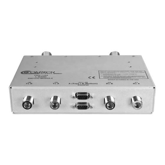
Chapter 1. INTRODUCTION Overview Figure 1-1. CRS-170A L-Band 1:1 Redundancy Switch The CRS‐170A L‐Band 1:1 Redundancy Switch module, shown in Figure 1‐1, is an L‐Band Tx‐Rx IF signal switch designed for use with L‐Band satellite modems in a 1:1 configuration. The Tx (transmit) side switches four modem output signals that are multiplexed onto the transmit coaxial cable: • 950‐1950 MHz L‐band transmit RF; • 10 MHz BUC frequency reference; • 600 KHz BUC FSK control and status communication; • BUC DC power supply. The Rx (receive) side of the switch uses both power dividers and relays to provide the redundant modem interface for three signals multiplexed onto the LNB coaxial cable: • 950‐1950 MHz L‐band receive RF from LNB; 1–1... -
Page 28: Table 1-1. Crs-170A Application Summary
Order modems with Type ‘N’ connectors. Firmware updates are free and may be downloaded from the Comtech EF Data web page. If a modem does not meet the hardware requirements, contact CEFD – hardware revision upgrades must be performed at CEFD ®... -
Page 29: 1.1.1 Modem Side Connectors
Control Interface with Modem A Control B DB-9F (9-pin Type ‘D’ female) Control Interface with Modem B TX A Type ‘N’ RF Output from Modem A TX B Type ‘N’ RF Output from Modem B Figure 1-2. CRS-170A – Modem Side Connectors 1–3... -
Page 30: 1.1.2 Antenna Side Connectors
Description Direction RF Input LNB 10 MHz Ref LNB Power RF Output BUC 10 MHz Ref BUC FSK In/Out Comm. Figure 1-3. CRS-170A – Antenna Side Connectors and Ground Lug Functional Description The CRS‐170A L‐Band 1:1 Redundancy Switch module performs the Tx and Rx coaxial switching required for redundant modem operation with an outdoor BUC and LNB. It switches all of the BUC and LNB interface signals that are multiplexed onto the Tx and Rx coaxial cables: • Tx and Rx L‐Band signals; •... -
Page 31: 1.2.1 Operation With Cdm-625 / 840 / 750 / 570L / 700 / 710 / 710G Modems
CRS-170A L-Band 1:1 Redundancy Switch Revision 9 Introduction MN/CRS170A.IOM 1.2.1 Operation with CDM-625 / 840 / 750 / 570L / 700 / 710 / 710G Modems The CRS‐170A is configured with two modems to form a complete 1:1 redundant modem ... - Page 32 CRS-170A L-Band 1:1 Redundancy Switch Revision 9 Introduction MN/CRS170A.IOM the Online and Offline demodulator. The Offline demodulator can then maintain lock so that it is ready to quickly assume Online status for receive traffic when a switchover is required. Data Switching is accomplished inside each modem, in the data interface itself. A ‘Y’ cable connects both the Online modem and the Offline modem to the terrestrial data source. ...
-
Page 33: 1:1 Ip Redundancy Data Switching - Functional Description
CRS-170A L-Band 1:1 Redundancy Switch Revision 9 Introduction MN/CRS170A.IOM 1.2.1.1 1:1 IP Redundancy Data Switching – Functional Description 1.2.1.1.1 CDM-570L (with Optional IP Module) – Managed Switch or Router Modes • Do not use the M&C Ethernet port (bottom RJ‐45 connector) when the optional IP Module is installed. • All configuration changes can only be made to the Online Modem and will ... -
Page 34: Figure 1-4. Cdm-570L 1:1 Ip Redundancy Router Mode - 'A' Online
CRS-170A L-Band 1:1 Redundancy Switch Revision 9 Introduction MN/CRS170A.IOM Figure 1-4. CDM-570L 1:1 IP Redundancy Router Mode – ‘A’ Online 1–8... -
Page 35: Cdm-625/750/700/710/710G Managed Switch Mode
CRS-170A L-Band 1:1 Redundancy Switch Revision 9 Introduction MN/CRS170A.IOM Figure 1-5. CDM-570L 1:1 IP Redundancy Router Mode – Switchover (‘B’ Online) 1.2.1.1.2 CDM-625/750/700/710/710G Managed Switch Mode A standard, user‐provided Ethernet Layer 2 Switch is needed when a CDM‐625, CDM‐750, CDM‐700, CDM‐710, or CDM‐710G modem is configured for Managed Switch Mode (also known ... -
Page 36: Figure 1-6. Cdm-625/750/700/710/710G 1:1 Ip Redundancy Managed Switch Mode
CRS-170A L-Band 1:1 Redundancy Switch Revision 9 Introduction MN/CRS170A.IOM Any new packets arriving destined for that MAC address will be forwarded only out the port identified in the CAM table. Most switch CAM tables do have a flush or timeout value, but is ... -
Page 37: Figure 1-7. Cdm-625/750/700/710/710G 1:1 Ip Redundancy Managed Switch Mode - Switchover
CRS-170A L-Band 1:1 Redundancy Switch Revision 9 Introduction MN/CRS170A.IOM CDM-625/750/700/710/710G CDM-625/750//700/710/710G CDM-625/750/700/710/710G/ Figure 1-7. CDM-625/750/700/710/710G 1:1 IP Redundancy Managed Switch Mode – Switchover ... -
Page 38: With Optional Ip Packet Processor) - Router Mode
CRS-170A L-Band 1:1 Redundancy Switch Revision 9 Introduction MN/CRS170A.IOM Note the following: 1. The Managed Switch Mode method of redundancy is intended to be equivalent to pulling the Ethernet cable from one port and putting it into a different port on the same switch. 2. For the CDM‐625 modem: The user may configure one of the CDM‐625’s four available ... -
Page 39: Figure 1-8. Cdm-625 1:1 Ip Redundancy Router Mode - 'A' Online
CRS-170A L-Band 1:1 Redundancy Switch Revision 9 Introduction MN/CRS170A.IOM Whichever modem is online will assume the Traffic IP. When there is a switchover to the backup modem, this modem will now assume the Traffic IP. Per Figure 1‐9, the backup modem will also broadcast a “gratuitous ARP” which will tell all local devices to now associate a new MAC address for the Traffic IP 172.18.10.20. Each device will update their ARP tables and traffic will resume virtually instantaneously. ... -
Page 40: 1.2.2 Operation With Cdm-600L (Clm-9600L) And Sdm-300L3
CRS-170A L-Band 1:1 Redundancy Switch Revision 9 Introduction MN/CRS170A.IOM Figure 1-9. CDM-625 1:1 IP Redundancy Router Mode – Switchover (‘B’ Online) 1.2.2 Operation with CDM-600L (CLM-9600L) and SDM-300L3 Operation with two CDM‐600L (CLM‐9600L) modems requires an additional CRS‐150 1:1 switch for terrestrial data switching and 1:1 control, while operation with two SDM‐300L3 modems ... - Page 41 CRS-170A L-Band 1:1 Redundancy Switch Revision 9 Introduction MN/CRS170A.IOM At the heart of the CRS‐150 is a Controller State Machine that is responsible for fault monitoring and control of switching functions – it is implemented in a CPLD. The CRS‐150 redundancy switch derives its operating power from the two modems (online and standby units) via extra power‐carrying wires in the data cable from each modem. Similarly, the CRS‐170A derives its +12V power from both modems through 'Y' cable connection to the same cables. The required online and offline control signals are also included in these cables. A diode sharing arrangement with a current sharing circuit ensures that power is taken equally from the two modems in normal operation. In the event that one of the two units is removed, however, the remaining modem can supply all current requirements. The modems supply +12 volts DC (at a combined total of 400 mA max) and ‐12 volts DC (at a combined total of 120 mA max). Maximum power consumption occurs in a serial LVDS mode at maximum data rate (20 Mbps). Power consumption in RS‐232 modes is ...
-
Page 42: Operation With Sdm-300L3 And Sms-301
CRS-170A L-Band 1:1 Redundancy Switch Revision 9 Introduction MN/CRS170A.IOM position and push the Switch Condition switches to the OFF position. See Section 3.7 Switch DIP Settings for detailed information. 1.2.4 Operation with SDM-300L3 and SMS-301 The SMS‐301 is modified from the standard version that operates with 70/140 MHz IF SDM‐300A modems. The BNC IF connectors are removed since the connectors and internal ... -
Page 43: Summary Of Specifications
CRS-170A L-Band 1:1 Redundancy Switch Revision 9 Introduction MN/CRS170A.IOM Summary of Specifications Equipment Type L-Band 1:1 Redundancy Switch Manufacturer Comtech EF Data, Tempe, Arizona Supported Comtech EF Data Modems • CDM-625 with/without optional IP Packet Processor • CDM-840 Remote Router •... - Page 44 CRS-170A L-Band 1:1 Redundancy Switch Revision 9 Introduction MN/CRS170A.IOM Dimensions [excluding connectors] 1.7 H x 5.7 W x 4.1 D inches (43 H x 143 W x 104 D mm) 19-inch rack mounting kit available. Power requirements • + 12 volts DC @ 130 mA (max) •...
-
Page 45: Installation
Chapter 2. INSTALLATION Unpacking and Inspection The CRS‐170A L‐Band 1:1 Redundancy Switch module and its Installation and Operation Manual were packaged and shipped in a reusable cardboard carton containing protective foam spacing. This equipment contains parts and assemblies sensitive to damage by Electrostatic Discharge (ESD). Use ESD precautionary procedures when handling the equipment. Once opened, inspect the shipment: Step Task 1 Keep all shipping materials for storage or reshipment. 2 Check the packing list to ensure the shipment is complete. Inspect the equipment for any possible damage incurred during shipment. Contact 3 the carrier and Comtech EF Data immediately to submit a damage report if damage is evident. Review this manual and the pertinent modem’s Installation and 4 Operation Manual carefully to become familiar with 1:1 redundancy operation. 5 Proceed to Sect. 2.2 Mounting. 2–1... -
Page 46: Mounting
CRS-170A L-Band 1:1 Redundancy Switch Revision 9 Installation MN/CRS170A.IOM Mounting Figure 2-1. KT/10254 Mounting Panel Kit (for horizontal or vertical mounting) The CRS‐170A is designed to be freestanding, or mounted in the rear of the rack containing the modems using the available Comtech EF Data Mounting Panel Kit KT/10254. As shown in Figure 2‐1, this kit allows the module to be mounted horizontally or vertically in the rack. In applications with the CDM‐600L (CLM‐9600L) and the CRS‐150, the CRS‐170A is best ... -
Page 47: Modem And Switch Configuration
Chapter 3. MODEM AND SWITCH CONFIGURATION Overview In order to avoid damage to the modems and CRS‐170A switch, it is important to follow this sequence of configuration: First, • configure the modems for 1:1 redundant operation as outlined in this chapter in Sect. 3.2 through Sect. 3.7. Second, • once the modems have been properly configured for 1:1 redundant operations, set the DIP switches on the CRS‐170A to the correct modem selection, as outlined in this chapter in Sect. 3.8 CRS‐170A Switch DIP Settings. - Page 48 CRS-170A L-Band 1:1 Redundancy Switch Revision 9 Modem and Switch Configuration MN/CRS170A.IOM This page is intentionally blank. ...
-
Page 49: Configuring Cdm-625S For 1:1 Redundancy
CRS-170A L-Band 1:1 Redundancy Switch Revision 9 Modem and Switch Configuration MN/CRS170A.IOM Configuring CDM-625s for 1:1 Redundancy CDM‐625 Advanced Satellite Modem Installation and Operation Manual (CEFD P/N MN‐CDM625) The CDM‐625 Advanced Satellite Modem automatically detects if it is connected to a 1:1 redundancy system – the steps required to configure both modems are therefore minimal, with some exceptions: • If the CDM‐625 has the optional IP Packet ... -
Page 50: Carrier-In-Carrier® Redundancy Configuration
CRS-170A L-Band 1:1 Redundancy Switch Revision 9 Modem and Switch Configuration MN/CRS170A.IOM 3.2.2 Carrier-in-Carrier® Redundancy Configuration ® If Carrier‐in‐Carrier (CnC) is utilized, the CnC control setting must be set to Redundancy mode using the CDM‐625 front panel menus. Configuration of the CnC control setting for CDM‐625 1:1 Redundancy is as follows: Step Procedure From the top-level SELECT: menu, navigate each menu level using the ◄► arrow keys and... -
Page 51: Cdm-840 Operation In 1:1 Redundancy
CRS-170A L-Band 1:1 Redundancy Switch Revision 9 Modem and Switch Configuration MN/CRS170A.IOM CDM-840 Operation in 1:1 Redundancy CDM‐840 Remote Router Installation and Operation Manual (CEFD P/N MN‐CDM840) The CDM‐840 Remote Router automatically detects if it is connected to a 1:1 redundancy system. With both units automatically configured for 1:1 operation, the online unit keeps the ... - Page 52 CRS-170A L-Band 1:1 Redundancy Switch Revision 9 Modem and Switch Configuration MN/CRS170A.IOM Notes: 3–6...
-
Page 53: Cdm-750 Operation In 1:1 Redundancy
CRS-170A L-Band 1:1 Redundancy Switch Revision 9 Modem and Switch Configuration MN/CRS170A.IOM CDM-750 Operation in 1:1 Redundancy CDM‐750 Advanced High‐Speed Trunking Modem Installation and Operation Manual (CEFD P/N MN‐CDM750) The CDM‐750 Advanced High‐Speed Trunking Modem automatically detects if it is connected to a 1:1 redundancy system. With both modems automatically configured for 1:1 operation, the online modem keeps the offline modem updated as online modem configuration changes ... - Page 54 CRS-170A L-Band 1:1 Redundancy Switch Revision 9 Modem and Switch Configuration MN/CRS170A.IOM Notes: 3–8...
-
Page 55: Configuring Cdm-570Ls For 1:1 Redundancy
CRS-170A L-Band 1:1 Redundancy Switch Revision 9 Modem and Switch Configuration MN/CRS170A.IOM Configuring CDM-570Ls for 1:1 Redundancy CDM‐570/CDM‐570L/CDMR‐570L Satellite Modem Installation and Operation Manual (CEFD P/N MN/CDM570L.IOM) For correct operation of the CRS‐170A, the CDM‐570L Satellite Modems must have the following installed: • Base Modem Firmware Version 1.6.7 (or higher) • IP Module Firmware Version 1.5.4.2 (or higher) • Hardware Revision 3 ... -
Page 56: Ip Redundancy Configuration
While monitoring the Serial console CLI on both modems, observe the following after powering on both modems at the same time (also observe the CRS-170A Online LEDs to see which modem is the Online modem). Online modem CLI displays: 1:1 Redundancy (Auto Detected) Redundancy: PARAM File Connection Established. -
Page 57: Non-Ip Redundancy Configuration
CRS-170A L-Band 1:1 Redundancy Switch Revision 9 Modem and Switch Configuration MN/CRS170A.IOM Figure 3-3. CDM-570L CLI 1:1 Redundancy Configuration screen All configuration changes can only be made to the Online Modem and will require the user to “Save Parameters to permanent storage” to ensure the ... - Page 58 CRS-170A L-Band 1:1 Redundancy Switch Revision 9 Modem and Switch Configuration MN/CRS170A.IOM Notes: 3–12...
-
Page 59: Configuring Cdm-700S/Cdm-710S/Cdm-710Gs For 1:1 Redundancy
CRS-170A L-Band 1:1 Redundancy Switch Revision 9 Modem and Switch Configuration MN/CRS170A.IOM Configuring CDM-700s/CDM-710s/CDM-710Gs for 1:1 Redundancy • CDM‐700 Satellite Modem Installation and Operation Manual (CEFD P/N MN/CDM700.IOM) • CDM‐710 Broadcast Satellite Modem Installation and Operation Manual (CEFD P/N CDM710.IOM) • CDM‐710G Satellite Modem Installation and Operation Manual (CEFD P/N MN‐CDM710G) For correct operation of the CRS‐170A, the CDM‐700, CDM‐710, or CDM‐710G ... -
Page 60: Ip Redundancy Configuration
Setup of the CDM‐700/CDM‐710/CDM‐710G modems for 1:1 IP Redundancy (i.e., when the terrestrial data type is GigE) is as follows: Step Procedure Before connecting the modems to the CRS-170A, you will need to first configure the following IP module settings on the modems. From the modem front panel: CONFIG AUX (Redundancy Mode) ENA/DIS set to Disable. -
Page 61: Cdm-600L (Clm-9600L) Operation In 1:1 Redundancy
CRS-170A L-Band 1:1 Redundancy Switch Revision 9 Modem and Switch Configuration MN/CRS170A.IOM CDM-600L (CLM-9600L) Operation in 1:1 Redundancy CLM‐9600L Open Network Satellite Modem Installation and Operation Manual (CEFD P/N MN/CLM9600L.IOM) The CDM‐600L (CLM‐9600L) Open Network Satellite Modems need no unique special 1:1 configuration settings. However, for correct operation of the CRS‐170A, the CDM‐600Ls must have the following installed: • Firmware Version 1.1.4 (or higher) • Hardware Revision 3 If the modems do not meet this requirement, contact Comtech EF Data. Firmware ... - Page 62 CRS-170A L-Band 1:1 Redundancy Switch Revision 9 Modem and Switch Configuration MN/CRS170A.IOM Notes: 3–16...
-
Page 63: Crs-170A Switch Dip Settings
On the next page, Table 3‐1 illustrates the settings for the ‘Mode’ DIP switch set on a per‐ modem basis, and the ‘Switch Conditions’ DIP switch settings that determine switchover functionality for a given redundancy configuration. Figure 3-4. CRS-170A Antenna Side – DIP Switches 3–17... -
Page 64: Table 3-1. Crs-170A Dip Switch Settings
CRS-170A L-Band 1:1 Redundancy Switch Revision 9 Modem and Switch Configuration MN/CRS170A.IOM Table 3-1. CRS-170A DIP Switch Settings ‘Mode’ DIP Settings ‘Switch Conditions’ DIP Settings Left Right Left Right Modem Result Switch Switch Switch Switch CDM-625 Down Switchover upon a Unit... -
Page 65: Cables And Connections
Chapter 4. CABLES AND CONNECTIONS Overview When assembling a Comtech EF Data 1:1 Redundancy System, in addition to purchasing the desired modem pair (one Redundant modem, one Traffic modem), the user must also purchase a redundancy kit tailored to that modem choice. This kit provides – in addition to the CRS‐170A L‐Band 1:1 Redundancy Switch module – all cables and components required for interconnection of the redundant configuration to various interfaces (i.e., control, IF, and data), excluding Ethernet, which requires user‐provided cables and Layer 2 switching. ... - Page 66 CRS-170A L-Band 1:1 Redundancy Switch Revision 9 Cables and Connections MN/CRS170A.IOM This page is intentionally blank. ...
-
Page 67: Cabling To The Cdm-625
4.2.4 for CDM‐625 terrestrial data interface configuration and connection examples and details. Comtech EF Data’s KT‐0000160 1:1 Redundancy Control/IF Interface Cabling Kit is required for control and L‐Band switch‐to‐modem cabling connections: KT-0000160 1:1 Redundancy Control / IF Interface Cabling Kit (CRS-170A CDM-625) Ch. 4 CEFD Part No. Qty Description Used For PL/10129-1 CRS-170A Switch – Top Assembly... -
Page 68: Modem-To-Switch Control Interface Connection
CRS-170A L-Band 1:1 Redundancy Switch Revision 9 Cables and Connections MN/CRS170A.IOM 4.2.2 Modem-to-Switch Control Interface Connection When connecting the Control cable between the CRS‐170A and the modems, ensure that screw locks on the ‘D’ type connectors are securely fastened. This will prevent the accidental unmating of the cable, particularly when a standby unit is being removed or replaced. CEFD Part No. Description CA/WR9378-4 Control Cable – Universal, DB-9M, 4’ Figure 4-1. CDM-625 Modem-to-Switch Control Connections... -
Page 69: Modem-To-Switch If Interface Connection
CRS-170A L-Band 1:1 Redundancy Switch Revision 9 Cables and Connections MN/CRS170A.IOM 4.2.3 Modem-to-Switch IF Interface Connection EXAMPLE: The Tx IF from ‘ Modem A’ connects to the Tx IF port ‘J5 Tx A’ on the CRS‐170A; similarly, the Tx IF from ‘Modem B’ connects to the Tx IF port ‘J6 Tx B’ on the CRS‐170A. The same logic applies for the Rx IF connections. It is important to note that failure to observe this requirement will result in system malfunction. 4.2.3.1 Modem-to-Switch L-Band (Rx/Tx) IF Interface Connection CEFD Part No. Description CA/RF10453-4 RoHS-Compliant Cable – IF (Tx/Rx), 50Ω Type ‘N’, 4’... -
Page 70: Modem-To-Switch L-Band Tx / 70/140 Mhz Rx If Interface Connection
CRS-170A L-Band 1:1 Redundancy Switch Revision 9 Cables and Connections MN/CRS170A.IOM 4.2.3.2 Modem-to-Switch L-Band Tx / 70/140 MHz Rx IF Interface Connection If the Tx IF is L‐Band and the Rx IF is 70/140MHz, additional items may be purchased for this option, as shown here in Figure 4‐3. Item CEFD Part No. Description CA/RF10453-4 RoHS-Compliant Cable – IF (Tx/Rx), 50Ω Type ‘N’, 4’... -
Page 71: Modem-To-User Data Interface Connections And Examples
CRS-170A L-Band 1:1 Redundancy Switch Revision 9 Cables and Connections MN/CRS170A.IOM 4.2.4 Modem-to-User Data Interface Connections and Examples Appendix A. CABLE DRAWINGS The data cables and components identified in each of the examples that follow in this section must be purchased separately, as required. In addition to the control and IF switch‐to‐modem cabling shown previously, a number of data interface configurations are available for the CDM‐625. The block diagram shown in Figure 4‐4 is typical for the examples shown in Sects. 4.2.4.1 through 4.2.4.9. ... -
Page 72: Rs-422/232 Interface Example
CRS-170A L-Band 1:1 Redundancy Switch Revision 9 Cables and Connections MN/CRS170A.IOM 4.2.4.1 RS-422/232 Interface Example CEFD Part No. Description CA/RB10461-1 Cable – 1:1 ‘Y’ Splitter, (2X) DB-25M DB-25F Figure 4-5. CDM-625 RS-422/232 1:1 Example 4.2.4.2 HSSI Interface Example ... -
Page 73: Asi Interface Example
CRS-170A L-Band 1:1 Redundancy Switch Revision 9 Cables and Connections MN/CRS170A.IOM 4.2.4.3 ASI Interface Example KT/12579 ASI 75Ω Interface Kit CEFD Part No. Description CA/BNC75OHM Cable – IF BNC, 75Ω, 1’ RF/SA32KC-IN/OUT Combiner – 2-way w/Bracket, 0.25-300 MHz, 75Ω BNC ... -
Page 74: Quad E1 Interface Example
CRS-170A L-Band 1:1 Redundancy Switch Revision 9 Cables and Connections MN/CRS170A.IOM 4.2.4.4 Quad E1 Interface Example The G.703 Balanced and Auxiliary G.703 DB‐9F single connectors are used for Quad E1 operation. Note the following: 1. As shown Figure 4‐8, the CA‐0000071 ‘Y’ Cable provides for two ports of E1 (i.e., Ports 1/2 ‐ or‐ Ports 3/4). 2. If the user desires three or four separate ports of E1 (i.e., Port 1 and Port 2 ‐or‐ Port 3 and Port 4), then optional adapter cables may be purchased from Comtech EF Data to adapt the G.703 Balanced and Auxiliary G.703 DB‐9F single connector pairs to outgoing Quad E1 ... -
Page 75: G.703 Balanced Interface Example
CRS-170A L-Band 1:1 Redundancy Switch Revision 9 Cables and Connections MN/CRS170A.IOM 4.2.4.5 G.703 Balanced Interface Example CEFD Part No. Description CA-0000071 Cable – 1:1 ‘Y’ Splitter, (2X) DB-9M DB-9F, 8” Figure 4-9. CDM-625 G.703 Balanced 1:1 Example 4.2.4.6 G.703 Unbalanced Interface Example... -
Page 76: Overhead Interface Example
CRS-170A L-Band 1:1 Redundancy Switch Revision 9 Cables and Connections MN/CRS170A.IOM 4.2.4.7 Overhead Interface Example CEFD Part No. Description CA-0000070 Cable – 1:1 ‘Y’ Splitter, (2X) HD-44M HD-44F, 8” Figure 4-11. CDM-625 Overhead 1:1 Example 4.2.4.8 Engineering Service Channel (ESC) Interface Example ... -
Page 77: 10/100 Ethernet Interface Examples
CRS-170A L-Band 1:1 Redundancy Switch Revision 9 Cables and Connections MN/CRS170A.IOM 4.2.4.9 10/100 Ethernet Interface Examples 4.2.4.9.1 Managed Switch Mode (with/without IP Packet Processor) Figure 4‐13 shows a block diagram and cabling example of a CDM‐625 1:1 modem configuration using the 10/100 Ethernet Interface in Managed Switch (Ethernet Bridge) Mode. Direct connection is made via one to four RJ‐45 ports using user‐provided Ethernet cables and Layer 2 switches, so no cables or kit is required. The cabling example depicts all four Ethernet ports used. CDM-625 Block Diagram: 10/100 Ethernet Interface – Managed Switch Mode ... -
Page 78: Router Mode (Optional Ip Packet Processor Required)
CRS-170A L-Band 1:1 Redundancy Switch Revision 9 Cables and Connections MN/CRS170A.IOM 4.2.4.9.2 Router Mode (Optional IP Packet Processor Required) Figure 4‐14 shows a block diagram and cabling example of a CDM‐625 1:1 modem configuration using the 10/100 Ethernet Interface in Router Mode, with the optional IP Packet Processor installed and enabled. Direct connection is made via only one of four RJ‐45 ports using user‐... -
Page 79: Data Interface Connections Using Ip Sub-Mux
® 4‐15 to connect and secure the CDM‐625 Multi‐drop CnC Plus 1:1 Cable CA‐0000276 (2X DB‐ 9M, 1’), required between the Redundant Modem and each Traffic Modem using CnC. The CA-0000276 Multi-Drop CnC PLUS 1:1 Cable bypasses the CRS-170A L-Band 1:1 Redundancy Switch. ® If CnC is enabled with a CDM‐625 1:1 pair, before any switch configurations can be made, ... - Page 80 CRS-170A L-Band 1:1 Redundancy Switch Revision 9 Cables and Connections MN/CRS170A.IOM Notes: 4–16...
-
Page 81: Cabling To The Cdm-840
Terrestrial data interface components/kits must be ordered separately. See Sect. 4.3.4 for CDM‐840 terrestrial data interface configuration and connection examples and details. Comtech EF Data’s KT‐0000160 1:1 Redundancy Control/IF Interface Cabling Kit is required for control and L‐Band switch‐to‐unit cabling connections: KT-0000160 1:1 Redundancy Control / IF Interface Cabling Kit (CRS-170A CDM-840) Ch. 4 CEFD Part No. Qty Description Used For 4-16 PL/10129-1 CRS-170A Switch –... -
Page 82: Unit-To-Switch Control Interface Connection
CRS-170A L-Band 1:1 Redundancy Switch Revision 9 Cables and Connections MN/CRS170A.IOM 4.3.2 Unit-to-Switch Control Interface Connection When connecting the Control cable between the CRS‐170A and the CDM‐840s, ensure that screw locks on the ‘D’ type connectors are securely fastened. This will prevent the accidental unmating of the cable, particularly when a standby unit is being removed or replaced. ... -
Page 83: Unit-To-Switch If Interface Connection
CRS-170A L-Band 1:1 Redundancy Switch Revision 9 Cables and Connections MN/CRS170A.IOM 4.3.3 Unit-to-Switch IF Interface Connection EXAMPLE: The Tx IF from ‘ Unit A’ connects to the Tx IF port ‘J5 Tx A’ on the CRS‐170A; similarly, the Tx IF from ‘Unit B’ connects to the Tx IF port ‘J6 Tx B’ on the CRS‐170A. The same logic applies for the Rx IF connections. It is important to note that failure to observe this requirement will result in system malfunction. CEFD Part No. Description CA/RF10453-4 RoHS-Compliant Cable – IF (Tx/Rx), 50Ω Type ‘N’, 4’... -
Page 84: Unit-To-User Data Interface Connections And Examples
CRS-170A L-Band 1:1 Redundancy Switch Revision 9 Cables and Connections MN/CRS170A.IOM 4.3.4 Unit-to-User Data Interface Connections and Examples In addition to the control and IF switch‐to‐unit cabling shown in the previous section, the CDM‐840 features a 10/100/1000 Gigabit Ethernet data interface and a G.703 Unbalanced E1 ... -
Page 85: Kt/12542 G.703 75Ω Data Interface Kit (For G.703 Unbalanced E1)
CRS-170A L-Band 1:1 Redundancy Switch Revision 9 Cables and Connections MN/CRS170A.IOM 4.3.4.2 KT/12542 G.703 75Ω Data Interface Kit (for G.703 Unbalanced E1) Figure 4‐19 shows the block diagram and a cabling example for a CDM‐840 1:1 configuration using the G.703 Unbalanced E1 Data Interface Kit KT/12542 that is required with the CDM‐840’s optional E1 Interface / RAN Optimization Hardware / FAST Feature upgrade. ... - Page 86 CRS-170A L-Band 1:1 Redundancy Switch Revision 9 Cables and Connections MN/CRS170A.IOM Notes: 4–22...
-
Page 87: Cabling To The Cdm-750
CRS-170A L-Band 1:1 Redundancy Switch Revision 9 Cables and Connections MN/CRS170A.IOM 4.3.4.3 Cabling to the CDM-750 1. For information on the CDM‐750’s 1:1 auto‐enable functionality, see: • Chapter 3. MODEM AND SWITCH CONFIGURATION • CDM‐750 Advanced High‐Speed Trunking Modem Installation and Operation Manual (CEFD P/N MN‐CDM750) 2. For information on the cables and cable assemblies specified in this section, see: • Appendix A. CABLE DRAWINGS 4.3.5 Modem-to-Switch Control and IF Interface Connection Terrestrial data interface components/kits must be ordered separately. See Sect. ... - Page 88 CRS-170A L-Band 1:1 Redundancy Switch Revision 9 Cables and Connections MN/CRS170A.IOM KT-0000160 1:1 Redundancy Control/IF Interface Cabling Kit (CRS-170A CDM-750) Item CEFD Part No. Description PL/10129-1 CRS-170A Switch – Top Assembly CA/WR9378-4 Control Cable – Universal, DB-9M DB-9M, 4’...
-
Page 89: Modem-To-User Data Interface Connections And Examples
CRS-170A L-Band 1:1 Redundancy Switch Revision 9 Cables and Connections MN/CRS170A.IOM 4.3.6 Modem-to-User Data Interface Connections and Examples In addition to the control and IF switch‐to‐modem cabling shown in the previous section, a number of data interface configuration kits are available for use with the CDM‐750. 4.3.6.1 RJ-45 Gigabit Ethernet Data Interface Example When ... -
Page 90: Optical Gigabit Ethernet Interface Option Example
CRS-170A L-Band 1:1 Redundancy Switch Revision 9 Cables and Connections MN/CRS170A.IOM 4.3.6.2 Optical Gigabit Ethernet Interface Option Example Figure 4‐22 depicts a CDM‐750 1:1 modem configuration using the FAST‐activated J7 Optical SFP port and optional Optical Gigabit Ethernet Interface module (CEFD P/N IC‐0000058). Depending on the mode – Single Mode or Multi Mode – installation involves use of either one CA‐0000560 Optical Single‐Mode Y‐Cable set, or one CA‐0000559 Multi‐Mode Y‐Cable set. Mode configuration is easily distinguished by the color of the cables; for Single‐Mode configurations, ... -
Page 91: Serial Data Interface Kit And Connection Examples
CRS-170A L-Band 1:1 Redundancy Switch Revision 9 Cables and Connections MN/CRS170A.IOM 4.3.6.3 Serial Data Interface Kit and Connection Examples For all CDM‐750 serial data interface configurations, separate cabling kits are needed. For each user interface, one interface kit per 1:1 modem pair is required (see examples for specified quantities). For example, Sect. 4.3.2.3.1 identifies the interface kit used for the G.703 PIIC data interface. Figure 4‐23 shows a block diagram typical for the kits shown in this section. Note that this ... - Page 92 CRS-170A L-Band 1:1 Redundancy Switch Revision 9 Cables and Connections MN/CRS170A.IOM 4.3.6.3.1 KT/12542 G.703 75Ω Data Interface Kit (for Single G.703 E3/T3 PIIC) KT/12542 G.703 75Ω Interface Cabling Kit (for Single G.703 E3/T3 PIIC) CEFD Part No.
-
Page 93: Cabling To The Cdm-570L
1. For information on the cables and cable assemblies specified in this section, see: • Appendix A. CABLE DRAWINGS 4.4.1 CRS-170A CDM-570 1:1 Redundancy Kit KT/10860-1 Reference to how the items provided in Redundancy Kit KT/10860‐1 are used with all possible CDM‐570L data interface configurations is as follows: KT/10860-1 1:1 Redundancy Kit – Interface Cabling Reference (CRS-170A CDM-570L) Qty/Kit Ch. 4 CEFD Part No. Description Used For (REF) 4-20 PL/10129-1 CRS-170A Switch – Top Assembly... -
Page 94: Modem-To-Switch Control Interface Connection
CRS-170A L-Band 1:1 Redundancy Switch Revision 9 Cables and Connections MN/CRS170A.IOM 4.4.2 Modem-to-Switch Control Interface Connection When connecting the Control cable between the CRS‐170A and the modems, ensure that screw locks on the ‘D’ type connectors are securely fastened. This will prevent the accidental unmating of the cable, particularly when a standby unit is being removed or replaced. CEFD Part No. Description CA/WR9378-4 Control Cable – Universal, DB-9M, 4’ Figure 4-25. CDM-570L Modem-to-Switch Control Connections 4–30... -
Page 95: Modem-To-Switch If Interface Connection
CRS-170A L-Band 1:1 Redundancy Switch Revision 9 Cables and Connections MN/CRS170A.IOM 4.4.3 Modem-to-Switch IF Interface Connection EXAMPLE: The Tx IF from ‘ Modem A’ connects to the Tx IF port ‘J5 Tx A’ on the CRS‐170A; similarly, the Tx IF from ‘Modem B’ connects to the Tx IF port ‘J6 Tx B’ on the CRS‐170A. The same logic applies for the Rx IF connections. It is important to note that failure to observe this requirement will result in system malfunction. ... -
Page 96: Modem-To-User Data Interface Connections And Examples
CRS-170A L-Band 1:1 Redundancy Switch Revision 9 Cables and Connections MN/CRS170A.IOM 4.4.4 Modem-to-User Data Interface Connections and Examples In addition to the control and IF switch‐to‐modem cabling shown previously, a number of data interface configurations are available for the CDM‐570L. The block diagram shown in Figure 4‐27 is typical for the examples shown in Sects. 4.4.4.1 through 4.4.4.3. With the exception of the 10/100 Ethernet Interface configuration shown in Sect. 4.4.4.4, where user‐provided Ethernet cables and hub are used, one cable/component set per 1:1 modem pair is required for each user interface (see examples for specified quantities). Figure 4-27. CDM-570L Block Diagram: User Modem Switch Traffic Unless otherwise specified, the interface cables and components identified in each of the examplesthat follow are provided in the KT/10860‐1 CDM‐570L 1:1 Redundancy Kit ... -
Page 97: Rs-422/232 Interface Example
CRS-170A L-Band 1:1 Redundancy Switch Revision 9 Cables and Connections MN/CRS170A.IOM 4.4.4.1 RS-422/232 Interface Example CEFD Part No. Description CA/RB10461-1 Cable – 1:1 ‘Y’ Splitter, (2X) DB-25M DB-25F Figure 4-28. CDM-570L RS-422/232 1:1 Example 4.4.4.2 G.703 Balanced Interface Example ... - Page 98 CRS-170A L-Band 1:1 Redundancy Switch Revision 9 Cables and Connections MN/CRS170A.IOM 4.4.4.3 G.703 Unbalanced Interface Example G.703 Unbalanced 1:1 Interface Kit KT/10553-1 CEFD Part No. Description CA/BNC75OHM Cable – IF BNC, 1’ CN/BNC-TEE-JPJ T-Adapter, 50Ω BNC Figure 4-30. CDM-570L G.703 Unbalanced 1:1 Example ...
-
Page 99: 10/100 Ethernet Interface Example
CRS-170A L-Band 1:1 Redundancy Switch Revision 9 Cables and Connections MN/CRS170A.IOM 4.4.4.4 10/100 Ethernet Interface Example Figure 4‐31 shows a block diagram and cabling example of a CDM‐570L 1:1 modem configuration using the 10/100 Ethernet Interface. User‐provided Ethernet cables are connected directly to the ports, so no cables or kit is required. For the CDM‐570L in Managed Switch (Ethernet Bridge) Mode, the user MUST use an external Ethernet hub to insure that traffic will continue after a switchover. If an Ethernet switch is used, there could be a several minute outage while the Ethernet ... - Page 100 CRS-170A L-Band 1:1 Redundancy Switch Revision 9 Cables and Connections MN/CRS170A.IOM Notes: 4–36...
-
Page 101: Cabling To The Cdm-700
CRS-170A L-Band 1:1 Redundancy Switch Revision 9 Cables and Connections MN/CRS170A.IOM Cabling to the CDM-700 1. For information on configuring the CRS‐170A L‐Band 1:1 Redundancy Switch and CDM‐700 Satellite Modems for 1:1 operation, see: • Chapter 3. MODEM AND SWITCH CONFIGURATION • CDM‐700 Satellite Modem Installation and Operation Manual (CEFD P/N MN/CDM700.IOM) 2. For information on the cables and cable assemblies specified in this section, see: • Appendix A. CABLE DRAWINGS 4.5.1 Modem-to-Switch Control and IF Interface Connection Appendix A. CABLE DRAWINGS Figure 4‐32 shows the control and IF connections for the CDM‐700 to the CRS‐170A. All control ... - Page 102 CRS-170A L-Band 1:1 Redundancy Switch Revision 9 Cables and Connections MN/CRS170A.IOM KT/12551 CRS-170A L-Band 1:1 Redundancy Kit Item CEFD Part No. Description PL/10129-1 CRS-170A Switch – Top Assembly CA/RF10453-4 Cable – RoHS-Compliant, L-Band Type ‘N’, 4’ CA/WR12135-1 (Notes 1, 2) Cable Assy –...
-
Page 103: Modem-To-User Data Interface Kit And Connection Examples
CRS-170A L-Band 1:1 Redundancy Switch Revision 9 Cables and Connections MN/CRS170A.IOM 4.5.2 Modem-to-User Data Interface Kit and Connection Examples In addition to the control and IF switch‐to‐modem cabling shown in the previous section, a number of data interface configurations are available for use with the CDM‐700. The kits featured in this section can be supplied with the CRS‐170A for use with the CDM‐700. Figure 4-33. CDM-700 Block Diagram: User... -
Page 104: Dual G.703 E3/T3/Sts-1 75Ω Data Interface (Cdi-10) Kit Kt/12582 And Hssi Data Interface (Cdi-60) Kit Kt/12586
CRS-170A L-Band 1:1 Redundancy Switch Revision 9 Cables and Connections MN/CRS170A.IOM 4.5.2.1 Dual G.703 E3/T3/STS-1 75Ω Data Interface (CDI-10) Kit KT/12582 and HSSI Data Interface (CDI-60) Kit KT/12586 Figure 4‐34 shows an example of a CDM‐700 1:1 modem configuration with the CDI‐10 Dual ... -
Page 105: 155Mb Copper Data Interface (Cdi-50) Kit Kt/12583
CRS-170A L-Band 1:1 Redundancy Switch Revision 9 Cables and Connections MN/CRS170A.IOM 4.5.2.2 155MB Copper Data Interface (CDI-50) Kit KT/12583 Figure 4‐35 shows an example of a CDM‐700 1:1 modem configuration with a CDI‐50 Data Interface installed in Slot 1 for use with 155MB Copper data, and Slot 2 empty. The figure ... -
Page 106: Mode)
CRS-170A L-Band 1:1 Redundancy Switch Revision 9 Cables and Connections MN/CRS170A.IOM 4.5.2.3 OC-3 Data Interface (CDI-50) Kits KT/12585 (Single-Mode) or KT/12584 (Multi-Mode) Figure 4‐36 depicts a CDM‐700 1:1 modem configuration with installation of one CDI‐50 Data Interface installed in Slot 1 for use with OC‐3 data, and Slot 2 empty. The figure depicts installation of one KT/12585 OC‐3 Single‐Mode Interface Kit. Multi‐Mode configurations use the KT/12584 ... -
Page 107: Gigabit Ethernet Data Interface (Cdi-70) Example
CRS-170A L-Band 1:1 Redundancy Switch Revision 9 Cables and Connections MN/CRS170A.IOM 4.5.2.4 Gigabit Ethernet Data Interface (CDI-70) Example See CEFD White Paper “Bridged Ethernet Interface Redundancy” available for download from Comtech EF Data’s Web site (www.comtechefdata.com). Figure 4‐37 shows an example of a CDM‐700 1:1 modem configuration with a CDI‐70 Gigabit Ethernet Data Interface installed in Slot 1, and Slot 2 empty. User‐provided Ethernet cables are ... - Page 108 CRS-170A L-Band 1:1 Redundancy Switch Revision 9 Cables and Connections MN/CRS170A.IOM Notes: 4–44...
-
Page 109: Cabling To The Cdm-710
CRS-170A L-Band 1:1 Redundancy Switch Revision 9 Cables and Connections MN/CRS170A.IOM Cabling to the CDM-710 1. For information on configuring the CRS‐170A L‐Band 1:1 Redundancy Switch with the CDM‐710 Broadcast Satellite Modems for 1:1 operation, see: • Chapter 3. MODEM AND SWITCH CONFIGURATION • CDM‐710 Broadcast Satellite Modem Installation and Operation Manual (CEFD P/N MN/CDM710.IOM) 2. For information on the cables and cable assemblies specified in this section, see: • Appendix A. CABLE DRAWINGS 4.6.1 Modem-to-Switch Control and IF Interface Connection Appendix A. CABLE DRAWINGS ... - Page 110 CRS-170A L-Band 1:1 Redundancy Switch Revision 9 Cables and Connections MN/CRS170A.IOM KT/12551 CRS-170A L-Band 1:1 Redundancy Kit Item CEFD Part No. Description PL/10129-1 CRS-170A Switch – Top Assembly CA/RF10453-4 Cable – RoHS-Compliant, L-Band Type ‘N’, 4’ CA/WR12135-1 (Notes 1, 2) Cable Assy –...
-
Page 111: Modem-To-User Data Interface Kit And Connection Examples
CRS-170A L-Band 1:1 Redundancy Switch Revision 9 Cables and Connections MN/CRS170A.IOM 4.6.2 Modem-to-User Data Interface Kit and Connection Examples In addition to the control and IF switch‐to‐modem cabling shown in the previous section, a number of data interface configuration kits are available for use with the CDM‐710. Figure 4-39. CDM-710 Block Diagram: User... -
Page 112: Asi 75Ω Data Interface (Cdi-40) Kit Kt/12579
CRS-170A L-Band 1:1 Redundancy Switch Revision 9 Cables and Connections MN/CRS170A.IOM 4.6.2.1 ASI 75Ω Data Interface (CDI-40) Kit KT/12579 Figure 4‐40 shows an example of a CDM‐710 1:1 modem configuration with the CDI‐40 ASI Data Interface installed in Slot 1, and Slot 2 empty. The figure depicts installation of one KT/12579 ASI Interface Kit. Be sure to connect to the lower BNC connectors labeled “1:1” on the CDI-40 ASI Data Interface. The Rx port on each interface has been tuned to be 3 dB higher amplitude to compensate for the presence of the RF/SA32KC-IN/OUT 2-way combiner. -
Page 113: Hssi Data Interface (Cdi-60) Interface Kit Kt/12586
CRS-170A L-Band 1:1 Redundancy Switch Revision 9 Cables and Connections MN/CRS170A.IOM 4.6.2.2 HSSI Data Interface (CDI-60) Interface Kit KT/12586 Figure 4‐41 shows an example of a CDM‐710 1:1 modem configuration with the CDI‐60 HSSI Data Interface installed in Slot 1, and Slot 2 empty. The figure depicts installation of one ... -
Page 114: Gigabit Ethernet Data Interface (Cdi-70) Example
CRS-170A L-Band 1:1 Redundancy Switch Revision 9 Cables and Connections MN/CRS170A.IOM 4.6.2.3 Gigabit Ethernet Data Interface (CDI-70) Example See CEFD White Paper “Bridged Ethernet Interface Redundancy” available for download from Comtech EF Data’s Web site (www.comtechefdata.com). Figure 4‐42 shows a block diagram and cabling example of a CDM‐710 1:1 modem configuration with a CDI‐70 Gigabit Ethernet Data Interface in Slot 2, and Slot 1 empty. User‐provided Ethernet cables are connected directly to the interface, so no kit is required. CDM-710 Gigabit Ethernet (GigE) Interface – Block Diagram Figure 4-42. -
Page 115: Modem-To-Switch Control And If Interface Connection
CRS-170A L-Band 1:1 Redundancy Switch Revision 9 Cables and Connections MN/CRS170A.IOM 1. For information on configuring the CRS‐170A L‐Band 1:1 Redundancy Switchwith the CDM‐710 Broadcast Satellite Modems for 1:1 operation, see: • Chapter 3. MODEM AND SWITCH CONFIGURATION • CDM‐710G High‐Speed Satellite Modem Installation and Operation Manual (CEFD P/N MN‐CDM710G.IOM) 2. For information on the cables and cable assemblies specified in this section, see: • Appendix A. CABLE DRAWINGS 4.7.1 Modem-to-Switch Control and IF Interface Connection Figure 4‐43 shows the control and IF connections for the CDM‐710G to the CRS‐170A. As with the CDM‐710, all control and IF components are provided for the CDM‐710G in the KT/12551 ... - Page 116 CRS-170A L-Band 1:1 Redundancy Switch Revision 9 Cables and Connections MN/CRS170A.IOM KT/12551 CRS-170A L-Band 1:1 Redundancy Kit Item CEFD Part No. Description PL/10129-1 CRS-170A Switch – Top Assembly CA/RF10453-4 Cable – RoHS-Compliant, L-Band Type ‘N’, 4’ CA/WR12135-1 (Notes 1,2) Cable Assy –...
-
Page 117: Modem-To-User Data Interface Kit And Connection Examples
CRS-170A L-Band 1:1 Redundancy Switch Revision 9 Cables and Connections MN/CRS170A.IOM 4.7.2 Modem-to-User Data Interface Kit and Connection Examples In addition to the basic switch‐to‐modem cabling shown in the previous section, there are a number of data interface configuration kits available for use with the CDM‐710G. ... -
Page 118: Single G.703 E3/T3/Sts-1 75Ω Data Interface (Cdi-10-1) Kit Kt/12583
CRS-170A L-Band 1:1 Redundancy Switch Revision 9 Cables and Connections MN/CRS170A.IOM 4.7.2.1 Single G.703 E3/T3/STS-1 75Ω Data Interface (CDI-10-1) Kit KT/12583 Figure 4‐45 shows an example of a CDM‐710G 1:1 modem configuration with the CDI‐10‐1 Single G.703 Data Interface installed in Slot 1, and Slot 2 empty. The figure depicts installation of one KT/12583 Single G.703 Interface Kit. MODEM A ... -
Page 119: Hssi Data Interface (Cdi-60) Kit Kt/12586
CRS-170A L-Band 1:1 Redundancy Switch Revision 9 Cables and Connections MN/CRS170A.IOM 4.7.2.2 HSSI Data Interface (CDI-60) Kit KT/12586 Figure 4‐46 shows an example of a CDM‐710G 1:1 modem configuration with the CDI‐60 HSSI Data Interface installed in Slot 1, and Slot 2 empty. The figure depicts installation of one KT/12586 HSSI Interface Kit. ... -
Page 120: Gigabit Ethernet Interface (Cdi-70) Example
CRS-170A L-Band 1:1 Redundancy Switch Revision 9 Cables and Connections MN/CRS170A.IOM 4.7.2.3 Gigabit Ethernet Interface (CDI-70) Example See CEFD White Paper “Bridged Ethernet Interface Redundancy” available for download from Comtech EF Data’s Web site (www.comtechefdata.com). Figure 4‐47 shows a block diagram and cabling example of a CDM‐710G 1:1 modem configuration with the CDI‐70 Gigabit Ethernet Data Interface installed in Slot 2, and Slot 1 ... -
Page 121: Cabling The Cdm-600L (Clm-9600L)
CRS-170A L-Band 1:1 Redundancy Switch Revision 9 Cables and Connections MN/CRS170A.IOM Cabling the CDM-600L (CLM-9600L) • Comtech EF Data CLM‐9600L Open Network Satellite Modem Installation and Operation Manual (CEFD P/N MN/CLM9600L.IOM) • Comtech EF Data CRS‐150 1:1 Redundancy Switch Installation and Operation ... -
Page 122: Cabling The Sdm-300L3
CRS-170A L-Band 1:1 Redundancy Switch Revision 9 Cables and Connections MN/CRS170A.IOM Cabling the SDM-300L3 • Comtech EF Data SDM‐300L3 Satellite Modem Installation and Operation Manual (CEFD P/N MN/SDM300L3.IOM) • Comtech EF Data SMS‐301 Redundancy Switch Installation and Operation Manual (CEFD P/N MN/SMS301.IOM) • Appendix A. CABLE DRAWINGS The block diagram shown in Figure 4‐49 depicts connection of a pair of SDM‐300L3 Satellite Modems together with the SMS‐301 and CRS‐170A switches. ... -
Page 123: Connector Pinouts
Antenna Side Connectors (Rev. A and later version shown) To maintain compliance with the European EMC Directive (EN55022, EN50082‐1) properly shielded cables are required for data I/O. Figure 5-1. CRS-170A – Modem and Antenna Side Connectors 5–1... -
Page 124: Modem Side: Type 'N' If Connectors
CRS-170A L-Band 1:1 Redundancy Switch Revision 9 Connector Pinouts MN/CRS170A.IOM Modem Side: Type ‘N’ IF Connectors Four 50Ω Type ‘N’ female connectors are provided on the modem side of the CRS‐170A L‐Band 1:1 Redundancy Switch module. Refer to Table 5‐1 for details. Table 5-1. Modem Side Type ‘N’ Connectors Type ‘N’... -
Page 125: J3 Control Connector - Modem 'A' (Top), Db-9F
CRS-170A L-Band 1:1 Redundancy Switch Revision 9 Connector Pinouts MN/CRS170A.IOM J3 Control Connector – Modem ‘A’ (Top), DB-9F The Modem ‘A’ Control connector is a 9‐pin Type ‘D’ female interface located on the modem side of the CRS‐170A L‐Band 1:1 Redundancy Switch module. Refer to Table 5‐2 for pin assignments. Table 5-2. J3 - Modem ‘A’ Control Connector Pin Assignments Pin # Signal Function... -
Page 126: J4 Control Connector - Modem 'B' (Bottom), Db-9F
CRS-170A L-Band 1:1 Redundancy Switch Revision 9 Connector Pinouts MN/CRS170A.IOM J4 Control Connector – Modem ‘B’ (Bottom), DB-9F The Modem ‘B’ Control connector is a 9‐pin Type ‘D’ female interface located on the modem side of the CRS‐170A L‐Band 1:1 Redundancy Switch module. Refer to Table 5‐3 for pin assignments. Table 5-3. J4 - Modem ‘B’ Control Connector Pin Assignments Pin # Signal Function Signal Name... -
Page 127: Antenna Side: Type 'N' If Connectors
CRS-170A L-Band 1:1 Redundancy Switch Revision 9 Connector Pinouts MN/CRS170A.IOM Antenna Side: Type ‘N’ IF Connectors The 50Ω female Type ‘N’ connectors on the antenna side of the CRS‐170A L‐Band 1:1 Redundancy Switch module provide the coaxial cable connections to the outdoor receive and transmit equipment (BUC and LNB). ... - Page 128 CRS-170A L-Band 1:1 Redundancy Switch Revision 9 Connector Pinouts MN/CRS170A.IOM Notes: 5–6...
-
Page 129: Appendix A. Cable Drawings
Appendix A. CABLE DRAWINGS Introduction This appendix contains drawings of cables used with the CRS‐170A L‐Band 1:1 Redundancy Switch. These cables are broken into two categories: Control Interface Cables and IF / Data Interface Cables. Each section provides illustrations of the cables’ technical specifications; Chapter 4. CABLES AND additionally, the tables cross‐reference each cable to the applicable modem‐specific cabling figures provided in CONNECTIONS . ... -
Page 130: Control Interface Cables
CRS-170A L-Band 1:1 Redundancy Switch Revision 9 Appendix A MN/CRS170A.IOM Control Interface Cables App. A CABLE CEFD REF Ch. 4 DESCRIPTION USED FOR (TYPE) USED WITH CRS-170A CDM-625 CDM-840 4-16 CA/WR9378-4 Universal Cable, Control DB-9M DB-9M, 4’ 1:1 Control CDM-750... -
Page 131: Universal Control Cable, Db-9M Db-9M
CRS-170A L-Band 1:1 Redundancy Switch Revision 9 Appendix A MN/CRS170A.IOM A.2.1 Universal Control Cable, DB-9M DB-9M Figure A-1. Universal Control Cable (CEFD P/N CA/WR9378-4) -
Page 132: Adapter Control Cable, Rohs, Db-9M Db-15F
CRS-170A L-Band 1:1 Redundancy Switch Revision 9 Appendix A MN/CRS170A.IOM A.2.2 Adapter Control Cable, RoHS, DB-9M DB-15F Figure A-2. Adapter Control Cable (CEFD P/N CA/WR12135-1) -
Page 133: Optional 'Y' Splitter Adapter Control Cable, (2X) Db-9M Db-15F
CRS-170A L-Band 1:1 Redundancy Switch Revision 9 Appendix A MN/CRS170A.IOM A.2.3 Optional ‘Y’ Splitter Adapter Control Cable, (2X) DB-9M DB-15F The optional CA/WR13011‐4 ‘Y’ Splitter Adapter Control Cable, sold separately, is used in replacement of the CA/WA12135‐1 cable. This cable permits user access to the Summary Fault Relay. Figure A-3. Optional ‘Y’ Splitter Adapter Control Cable, (CEFD P/N CA/WR13011-4) -
Page 134: Optional Control Cable, Non-Muting, Db-9M Db-15F
CRS-170A L-Band 1:1 Redundancy Switch Revision 9 Appendix A MN/CRS170A.IOM A.2.4 Optional Control Cable, Non-muting, DB-9M DB-15F The optional CA‐0000187 Control Cable, sold separately, is used in replacement of the CA/WA12135‐1 cable. This cable keeps the offline modem’s Tx IF‐enabled. Figure A-4. Optional Control Cable (CEFD P/N CA-0000187) -
Page 135: Data / Control 'Y' Cable, Modem To Crs-170A And Crs-150, Db-25M Db-25M, Db-9M
CRS-170A L-Band 1:1 Redundancy Switch Revision 9 Appendix A MN/CRS170A.IOM A.2.5 Data / Control ‘Y’ Cable, Modem to CRS-170A and CRS-150, DB-25M DB-25M, DB-9M Figure A-5. Data / Control ‘Y’ Cable (CEFD P/N CA/WR10456-4) -
Page 136: Control Cable, Modem To Crs-170A And Sms-301, Db-9M Db-15M
CRS-170A L-Band 1:1 Redundancy Switch Revision 9 Appendix A MN/CRS170A.IOM A.2.6 Control Cable, Modem to CRS-170A and SMS-301, DB-9M DB-15M Figure A-6. Control Cable (CEFD P/N CA/WR10163-1) ... - Page 137 CRS-170A L-Band 1:1 Redundancy Switch Revision 9 Appendix A MN/CRS170A.IOM This page is intentionally blank. ...
-
Page 138: If / Data Interface Cables
CRS-170A L-Band 1:1 Redundancy Switch Revision 9 Appendix A MN/CRS170A.IOM IF / Data Interface Cables App. A REF Ch. 4 CABLE CEFD P/N DESCRIPTION USED FOR (TYPE) USED WITH CRS-170A CDM-625 CDM-625 CDM-840 4-17 CDM-750 4-20 CDM-570L 4-26 CA/RF10453-4 RoHS Coax Cable, Type ‘N’ 50Ω, 4’... - Page 139 CRS-170A L-Band 1:1 Redundancy Switch Revision 9 Appendix A MN/CRS170A.IOM App. A REF Ch. 4 CABLE CEFD P/N DESCRIPTION USED FOR (TYPE) USED WITH CRS-170A Quad E1 Data Interface CDM-625 A-10 CA-0000071 1:1 ‘Y’ Splitter Cable, (2X) DB-9M DB-9F, 8”...
-
Page 140: Modem To Crs-170A, L-Band Coaxial Cable, Rohs, Type 'N' 50Ω
CRS-170A L-Band 1:1 Redundancy Switch Revision 9 Appendix A MN/CRS170A.IOM A.3.1 Modem to CRS-170A, L-Band Coaxial Cable, RoHS, Type ‘N’ 50Ω Figure A-7. Tx/Rx 50Ω Type ‘N’ Coaxial Cable (CEFD P/N CA/RF10453-4) ... - Page 141 CRS-170A L-Band 1:1 Redundancy Switch Revision 9 Appendix A MN/CRS170A.IOM A.3.2 Modem to CRS-170A or User, 70/140 MHz Coaxial Cable, RoHS, Type ‘BNC’ 75Ω Figure A-8. Tx/Rx/User Data 75Ω Type ‘BNC’ Coaxial Cable (CEFD P/N CA/BNC75OHM) A-13...
-
Page 142: Modem To User, Splitter Cable, (2X) Db-25M Db-25F
CRS-170A L-Band 1:1 Redundancy Switch Revision 9 Appendix A MN/CRS170A.IOM A.3.3 Modem to User, Splitter Cable, (2X) DB-25M DB-25F Figure A-9. 1:1 User Data Splitter Cable (CEFD P/N CA/RB10461-1) A-14... -
Page 143: Modem To User, Cdm-625 Data 'Y' Splitter Cable, (2X) Db-9M Db-9F
CRS-170A L-Band 1:1 Redundancy Switch Revision 9 Appendix A MN/CRS170A.IOM A.3.4 Modem to User, CDM-625 Data ‘Y’ Splitter Cable, (2X) DB-9M DB-9F Figure A-10. 1:1 User Data ‘Y’ Splitter Cable (CEFD P/N CA-0000071) A-15... -
Page 144: Modem To User, Quad E1 'Y' Splitter Adapter Cable, (2X) Db-15F Db-9M
CRS-170A L-Band 1:1 Redundancy Switch Revision 9 Appendix A MN/CRS170A.IOM A.3.5 Modem to User, Quad E1 ‘Y’ Splitter Adapter Cable, (2X) DB-15F DB-9M This optional adapter cable may be purchased from Comtech EF Data to adapt the Balanced G.703 or Auxiliary G.703 DB‐9F modem ... -
Page 145: Modem To User, Quad E1 'Y' Splitter Adapter Cable, (2X) Rj-48F Db-9M
CRS-170A L-Band 1:1 Redundancy Switch Revision 9 Appendix A MN/CRS170A.IOM A.3.6 Modem to User, Quad E1 ‘Y’ Splitter Adapter Cable, (2X) RJ-48F DB-9M This optional adapter cable may be purchased from Comtech EF Data to adapt the Balanced G.703 or Auxiliary G.703 DB‐9F modem ... -
Page 146: Modem To User, Quad E1 'Y' Splitter Adapter Cable Kit (Kt-0000122)
CRS-170A L-Band 1:1 Redundancy Switch Revision 9 Appendix A MN/CRS170A.IOM A.3.7 Modem to User, Quad E1 ‘Y’ Splitter Adapter Cable Kit (KT-0000122) KT-0000122 Quad E1 Balanced/Unbalanced Adapter Kit CEFD P/N DESCRIPTION CA-0000347 ‘Y’ Cable Assy: DB-9M 2X RJ-48 Male... -
Page 147: Modem To User, Overhead User Data 'Y' Splitter Cable, (2X) Hd-44M Hd-44F
CRS-170A L-Band 1:1 Redundancy Switch Revision 9 Appendix A MN/CRS170A.IOM A.3.8 Modem to User, Overhead User Data ‘Y’ Splitter Cable, (2X) HD-44M HD-44F Figure A-14. Overhead User Data ‘Y’ Splitter Cable (CEFD P/N CA-0000070) A-19... -
Page 148: Modem To Modem Shielded Multi-Drop Cnc ® Plus, Cdm-625 1:1 Cable, Db-9M Db-9M
CRS-170A L-Band 1:1 Redundancy Switch Revision 9 Appendix A MN/CRS170A.IOM ® A.3.9 Modem to Modem Shielded Multi-drop CnC Plus, CDM-625 1:1 Cable, DB-9M DB-9M ® Figure A-15. Modem to Modem Shielded Multi-drop CnC Plus, CDM-625 1:1 Cable (CEFD P/N CA-0000276) ... -
Page 149: Modem To User, Optical Gigabit Ethernet Single-Mode Or Multi-Mode Cable Assemblies, (2X) Type 'Lc' (4X) Type 'Lc
CRS-170A L-Band 1:1 Redundancy Switch Revision 9 Appendix A MN/CRS170A.IOM A.3.10 Modem to User, Optical Gigabit Ethernet Single-Mode OR Multi-Mode Cable Assemblies, (2X) Type ‘LC’ (4X) Type ‘LC’ ... -
Page 150: Modem To User, G.703 Balanced User Data 'Y' Splitter Cable, (2X) Db-15M Db-15M
CRS-170A L-Band 1:1 Redundancy Switch Revision 9 Appendix A MN/CRS170A.IOM A.3.11 Modem to User, G.703 Balanced User Data ‘Y’ Splitter Cable, (2X) DB-15M DB-15M Figure A-17. G.703 Balanced User Data ‘Y’ Splitter Cable (CEFD P/N CA/WR10522-1) A-22... -
Page 151: Modem To User, Hssi User Data 'Y' Splitter Cable, (2X) Hd-50M Hd-50F
CRS-170A L-Band 1:1 Redundancy Switch Revision 9 Appendix A MN/CRS170A.IOM A.3.12 Modem to User, HSSI User Data ‘Y’ Splitter Cable, (2X) HD-50M HD-50F ... -
Page 152: Modem To User, Oc-3 Single-Mode Or Multi-Mode Cable Assemblies, Type 'Sc/Upc' (2X) Type 'Sc/Upc
CRS-170A L-Band 1:1 Redundancy Switch Revision 9 Appendix A MN/CRS170A.IOM A.3.13 Modem to User, OC-3 Single-Mode OR Multi-Mode Cable Assemblies, Type ‘SC/UPC’ (2X) Type ‘SC/UPC’ CEFD P/N Description Comments ‘Y’ Cable Assy – RoHS-Compliant, Optical Coupler (Single- or Multi-Mode), 7’, Type For CDM-700 Single-Mode OC-3 Interface;... -
Page 153: Metric Conversions
METRIC CONVERSIONS Units of Length Unit Millimeter Centimeter Inch Foot Yard Meter Kilometer Mile 1 millimeter 0.0394 0.0033 0.0011 0.001 1 x 10 6.214 x 10 1 centimeter 0.3937 0.0328 0.0109 0.01 1 x 10 6.214 x 10 1 inch 25.4 2.54 0.0833... - Page 154 2114 85281 WEST TH STREET TEMPE ARIZONA 480 • 333 • 2200 PHONE 480 • 333 • 2161...
Need help?
Do you have a question about the CRS-170A and is the answer not in the manual?
Questions and answers