
Related Manuals for Comtech EF Data CRS-170


Summary of Contents for Comtech EF Data CRS-170
- Page 1 CRS-170 1:1 Redundancy Switch Accessory Product for use only with Comtech EF Data CDM-600L and SDM-300L3 Modems (Modem Firmware and Hardware Requirements Apply) Part Number MN/CRS170.IOM Revision 1...
- Page 3 CRS-170 1:1 Redundancy Switch Accessory Product for use only with Comtech EF Data CDM-600L and SDM-300L3 Modems (Modem Firmware and Hardware Requirements Apply) Part Number MN/CRS170.IOM Revision 1 Comtech EF Data is an ISO 9001 October 4, 2004 Registered Company.
- Page 4 3. To ensure that the product is not damaged during shipping, pack the product in its original shipping carton/packaging. 4. Ship the product back to Comtech EF Data. (Shipping charges should be prepaid.) For more information regarding the warranty policies, see Warranty Policy, p. 13.
-
Page 5: Table Of Contents
Table of Contents CHAPTER 1. INTRODUCTION .................. 15 CHAPTER 2. INSTALLATION..................16 Unpacking........................16 Mounting ........................20 Cabling with CDM-600L and CRS-150 .................21 Cabling with SDM-300L3 and SMS-301 ...............22 CHAPTER 3. FUNCTIONAL DESCRIPTION ............... 23 Operation with CDM-600L and CRS-150 ..............24 Operation with SDM-300L3 and SMS-301 ..............25 CHAPTER 4. - Page 6 Figure 4. Modem Side of Module....................27 Figure 5. Antenna Side Connectors and Ground Lug..............31 Tables Table 1. CRS-170 Application Summary ...................17 Table 2. J3A - Modem A Control Connector Pin Assignments ..........28 Table 3. J3B - Modem B Control Connector Pin Assignments ..........29...
- Page 7 ANUAL This manual provides installation and operation information for the Comtech EF Data CRS-170 1:1 Redundancy Switch. This is a technical document intended for earth station engineers, technicians, and operators responsible for the operation and maintenance of the CRS-170 1:1 Redundancy Switch.
- Page 8 This equipment meets the electromagnetic compatibility/generic immunity standard as defined in EN50082-1. In order that the CRS-170 continues to comply with these standards, observe the following instructions: Connections to the transmit and receive IF ports (BNC female connectors) should be made using a good quality coaxial cable;...
- Page 9 DC operating current (electronically fused and protected) and control signals for the correct functioning of this unit. Connection to other manufacturer’s equipment could result in damage to the unit. The CRS-170 is not compatible with other Comtech EF Data modems.
- Page 10 Revision 1 Installation and Operations Manual MN/CRS170.IOM NVIRONMENTAL The CRS-170 must not be operated in an environment where the unit is exposed to extremes of temperature outside the ambient range 0 to 50 C (32 to 122 F), precipitation, condensation, or humid atmospheres above 95% RH, altitudes (un-pressurized) greater than 2000 meters, excessive dust or vibration, flammable gases, corrosive or explosive atmospheres.
- Page 11 For equipment under warranty, the customer is responsible for freight to Comtech EF Data and all related custom, taxes, tariffs, insurance, etc. Comtech EF Data is responsible for the freight charges only for return of the equipment from the factory to the customer.
- Page 12 CRS-170 1:1 Redundancy Switch Revision 1 Installation and Operations Manual MN/CRS170.IOM Notes: ________________________________________________________________________ ________________________________________________________________________ ________________________________________________________________________ ________________________________________________________________________ ________________________________________________________________________ ________________________________________________________________________ ________________________________________________________________________ ________________________________________________________________________ ________________________________________________________________________ ________________________________________________________________________ ________________________________________________________________________ ________________________________________________________________________ ________________________________________________________________________ ________________________________________________________________________ ________________________________________________________________________ ________________________________________________________________________ ________________________________________________________________________ ________________________________________________________________________ ________________________________________________________________________ ________________________________________________________________________ ________________________________________________________________________ ________________________________________________________________________ ________________________________________________________________________ ________________________________________________________________________ ________________________________________________________________________ ________________________________________________________________________ ________________________________________________________________________ ________________________________________________________________________...
-
Page 13: Chapter 1. Introduction
L-Band 1:1 Switch Module The CRS-170 L-Band 1:1 Switch Module is an L-Band Tx-Rx signal switch designed for use with L-Band satellite modems in a 1:1 configuration. The Tx side switches four modem output signals that are multiplexed onto the transmit coaxial cable: •... - Page 14 The CDM-600L and SDM-300L3 modems do not have built in switching capability for the terrestrial data side of the link. One-for-one redundancy for the CDM-600L requires both a CRS-150 switch to act as controller and terrestrial data switch, and a CRS-170 to perform the RF side switching.
-
Page 15: Table 1. Crs-170 Application Summary
CRS-170 1:1 Redundancy Switch Revision 1 Installation and Operations Manual MN/CRS170.IOM Table 1. CRS-170 Application Summary Modem 1:1 L-Band Switch 1:1 Data Switch Other Information (see Note 1) (see Note 2) (see Note 3) CDM-600L CRS-170 CRS-150 Firmware 1.1.4 or higher. -
Page 16: Installation And Operations Manual Mn/Crs170.Iom
CRS-170 1:1 Redundancy Switch Revision 1 Installation and Operations Manual MN/CRS170.IOM Note: ______________________________________________________________________________ ______________________________________________________________________________ ______________________________________________________________________________ ______________________________________________________________________________ ______________________________________________________________________________ ______________________________________________________________________________ ______________________________________________________________________________ ______________________________________________________________________________ ______________________________________________________________________________ ______________________________________________________________________________ ______________________________________________________________________________ ______________________________________________________________________________ ______________________________________________________________________________ ______________________________________________________________________________ ______________________________________________________________________________ ______________________________________________________________________________ ______________________________________________________________________________ ______________________________________________________________________________ ______________________________________________________________________________ ______________________________________________________________________________ ______________________________________________________________________________ ______________________________________________________________________________ ______________________________________________________________________________ ______________________________________________________________________________ ______________________________________________________________________________ ______________________________________________________________________________ ______________________________________________________________________________ ______________________________________________________________________________... -
Page 17: Chapter 2. Installation
Comtech EF Data immediately and submit a damage report. Be sure to keep all shipping materials for the carrier's inspection. If the unit needs to be returned to Comtech EF Data, use the original shipping container. -
Page 18: Mounting
MN/CRS170.IOM OUNTING The CRS-170 is designed to be mounted in the rear of a rack containing the modems. Because of the module’s small size and weight, one installation option is to let the module hang freely supported by the interfacing cables. Alternatively, a rack mounting kit (KT/10254) is available that allows the module to be mounted to the rack horizontally or vertically as shown in Figure 1. -
Page 19: Cabling With Cdm-600L And Crs-150
Carries Rx L - Band, LNB DC, 10 MHz Figure 2. Connection Diagram, CDM-600L and CRS-150 The following table lists cable assemblies that may be supplied with the CRS-170 when used with the CDM-600L and CRS-150. Other cables between the CRS-150 and the CDM-600L modems are supplied with the CRS-150. -
Page 20: Cabling With Sdm-300L3 And Sms-301
SMS-301 and CRS-170 switches. The same configuration applies to SNM-1001L and SNM-1010L. The following table lists cable assemblies that may be supplied with the CRS-170 when used with the SDM-300L3 and SMS-301. The other cables between the SMS-301 and the SDM-300L3 are the same cables supplied with the SMS-301 in an SDM-300A application. -
Page 21: Chapter 3. Functional Description
MN/CRS170.IOM Chapter 3. FUNCTIONAL DESCRIPTION The CRS-170 L Band 1:1 Switch module performs the transmit and receive coaxial switching required for redundant modem operation with an outdoor BUC and LNB. It switches all of the BUC and LNB interface signals that are multiplexed onto the transmit and receive coaxial cables: •... -
Page 22: Operation With Cdm-600L And Crs-150
IF signals, 10MHz reference signals, DC power for the BUC and LNB, and FSK signaling to the BUC are switched in the CRS-170 under control of the CRS-150. In the case of an equipment failure, switching automatically takes place to protect the traffic circuit. -
Page 23: Operation With Sdm-300L3 And Sms-301
At the same time, a green LED will illuminate on the front of the CRS-150 to indicate whether the ‘A’ or ‘B’ unit is online, and a green LED on the antenna side of the CRS-170 will indicate the same status. 3.2 O... - Page 24 CRS-170 1:1 Redundancy Switch Revision 1 Installation and Operations Manual MN/CRS170.IOM Note: ________________________________________________________________________ ________________________________________________________________________ ________________________________________________________________________ ________________________________________________________________________ ________________________________________________________________________ ________________________________________________________________________ ________________________________________________________________________ ________________________________________________________________________ ________________________________________________________________________ ________________________________________________________________________ ________________________________________________________________________ ________________________________________________________________________ ________________________________________________________________________ ________________________________________________________________________ ________________________________________________________________________ ________________________________________________________________________ ________________________________________________________________________ ________________________________________________________________________ ________________________________________________________________________ ________________________________________________________________________ ________________________________________________________________________ ________________________________________________________________________ ________________________________________________________________________ ________________________________________________________________________ ________________________________________________________________________ ________________________________________________________________________ ________________________________________________________________________ ________________________________________________________________________...
-
Page 25: Chapter 4. Connector Pinouts
Installation and Operations Manual MN/CRS170.IOM Chapter 4. CONNECTOR PINOUTS ODEM ONNECTORS The modem side connectors provide all necessary external connections between the CRS-170 L-Band Switch Module and the CDM-600L/CRS-150, or SDM- 300L3/SMS-301. Name Ref Des Connector Type Function RX A... -
Page 26: Modem A Control Connector
CRS-170 1:1 Redundancy Switch Revision 1 Installation and Operations Manual MN/CRS170.IOM 4.1.1 ODEM ONTROL ONNECTOR The Modem A Control connector is a 9-pin D female interface located on the modem side of the L-Band Switch Module. Refer to Table 2 for pin assignments. -
Page 27: Modem B Control Connector
CRS-170 1:1 Redundancy Switch Revision 1 Installation and Operations Manual MN/CRS170.IOM 4.1.2 ODEM ONTROL ONNECTOR The Modem B Control connector is a 9-pin D female interface located on the modem side of the L-Band Switch Module. Refer to Table 3 for pin assignments. -
Page 28: Modem Side Type N Connector
CRS-170 1:1 Redundancy Switch Revision 1 Installation and Operations Manual MN/CRS170.IOM 4.1.3 ODEM ONNECTORS There are four 50Ω Type N female connectors located on the modem side of the L-Band Switch Module. Refer to Table 4 for details. Table 4. Modem Side Type N Connectors... -
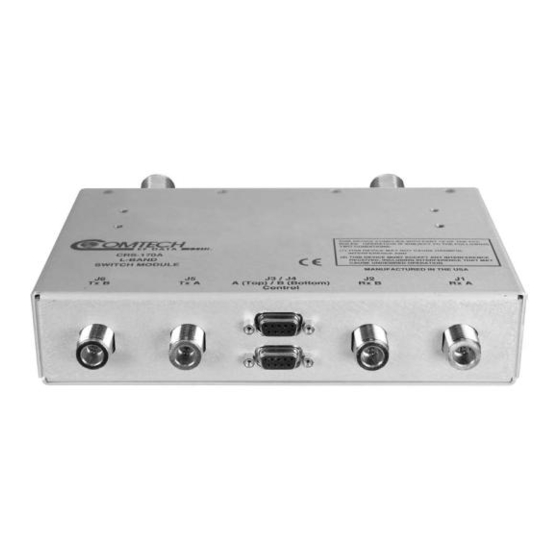
Page 29: Antenna Side Connectors
MN/CRS170.IOM NTENNA ONNECTORS Two 50Ω female Type N connectors on the antenna side of the CRS-170 L-Band Switch Module provide the coaxial cable connections to the outdoor transmit and receive equipment (BUC and LNB). Refer to Figure 5. Type N Connector... - Page 30 CRS-170 1:1 Redundancy Switch Revision 1 Installation and Operations Manual MN/CRS170.IOM Note: ________________________________________________________________________ ________________________________________________________________________ ________________________________________________________________________ ________________________________________________________________________ ________________________________________________________________________ ________________________________________________________________________ ________________________________________________________________________ ________________________________________________________________________ ________________________________________________________________________ ________________________________________________________________________ ________________________________________________________________________ ________________________________________________________________________ ________________________________________________________________________ ________________________________________________________________________ ________________________________________________________________________ ________________________________________________________________________ ________________________________________________________________________ ________________________________________________________________________ ________________________________________________________________________ ________________________________________________________________________ ________________________________________________________________________ ________________________________________________________________________ ________________________________________________________________________ ________________________________________________________________________ ________________________________________________________________________ ________________________________________________________________________ ________________________________________________________________________ ________________________________________________________________________...
-
Page 31: Chapter 5. Summary Of Specifications
L-Band 1:1 Redundancy Switch Manufacturer Comtech EF Data, Tempe, Arizona Modems Comtech EF Data CDM-600L with CRS-150 1:1 Data Switch Supported Comtech EF Data SDM-300L3 with SMS-301 1:1 Data Switch Operating Modes Fully Automatic under control of supporting 1:1 switch. - Page 32 CRS-170 1:1 Redundancy Switch Revision 1 Installation and Operations Manual MN/CRS170.IOM Weight 1.75lbs (0.8kg) Dimensions 1.75 H x 8.2 W x 5.3 inches (44.5H x 208.2W x 134.6 D mm (excluding connectors)) 19-inch rack mounting kit available. Power 1.5 Watts maximum...
- Page 33 METRIC CONVERSIONS Units of Length Unit Centimeter Inch Foot Yard Mile Meter Kilometer Millimeter 1 centimeter — 0.3937 0.03281 0.01094 6.214 x 10 0.01 — — 1 inch 2.540 — 0.08333 0.2778 1.578 x 10 0.254 — 25.4 1 foot 30.480 12.0 —...
- Page 34 2114 85281 WEST TH STREET TEMPE ARIZONA 480 • 333 • 2200 PHONE 480 • 333 • 2161...
Need help?
Do you have a question about the CRS-170 and is the answer not in the manual?
Questions and answers