Table of Contents
Advertisement
Quick Links
Advertisement
Table of Contents

Subscribe to Our Youtube Channel
Summary of Contents for Matrix Vision mvHYPERION-Series
- Page 1 Technical Manual...
-
Page 2: Table Of Contents
Settings behavior during startup ........MATRIX VISION GmbH... - Page 3 10.2 How to use the HRTC ......... 107 MATRIX VISION GmbH...
- Page 4 15.3.3 Make silent registration ........119 16 Glossary MATRIX VISION GmbH...
- Page 5 17.6.3 AcquisitionStart ........139 17.7 Synchronous acquisition with different camera settings ......140 MATRIX VISION GmbH...
-
Page 6: About This Manual
1.2.1 Introduction This chapter gives you a short overview, how to get started with a MATRIX VISION frame grabber and where to find the necessary information in the manual. It will also explain or link to the concepts behind the driver and the image acquisition. -
Page 7: Basics
1.2.2 Basics 1.2.2.1 Driver concept The driver supplied with the MATRIX VISION product represents the port between the programmer and the hardware. The driver concept of MATRIX VISION provides a standardized programming interface to all image processing products (excluding mvBlueLYNX) made by MATRIX VISION GmbH. - Page 8 Acquire device. No additional steps are needed. MATRIX VISION devices that also comply with the GigE Vision or USB3 Vision standard don't need any software at all, but can also use VisionPro's built-in GigE Vision or USB3 Vision support.
-
Page 9: Image Acquisition Concept
No additional steps are needed. MATRIX VISION devices that also comply with the GigE Vision or USB3 Vision standard don't need any software at all, but can also use HALCON's built-in GigE Vision or USB3 Vision support. -
Page 10: Programming
"mvIMPACT Acquire" interface references. Additionally, please have a look at the example programs. Several basic examples are available. The separate mvIMPACT Acquire manuals • "mvIMPACT_Acquire_API_CPP_manual.chm", • "mvIMPACT_Acquire_API_C_manual.chm", and • "mvIMPACT_Acquire_API_NET_manual.chm" are available as downloads from our website http://www.matrix-vision.com MATRIX VISION GmbH... -
Page 11: Imprint
MATRIX VISION website. MATRIX VISION cannot guarantee that the data is free of errors or is accurate and complete and, therefore, as- sumes no liability for loss or damage of any kind incurred directly or indirectly through the use of the information of this document. -
Page 12: Revisions
Added chapter "Porting existing code written with versions earlier then 1.12.0". 16. Dec. 2009 Added frame grabber mvHYPERION-32R16 (p. 38). 15. Dec. 2009 Added frame grabber mvHYPERION-HD-SDI (p. 41). 10. Nov. 2009 Added Windows 7 as supported operating system. MATRIX VISION GmbH... - Page 13 Rewritten "How to use this manual". This book now includes a getting started chapter (see: Composition of the manual (p. 2)). 19. Jun. 2007 Changed installation sequence Quickstart (p. 15). 12. Mar. 2007 Added Linux installation chapter Linux (p. 20). Feb. 2007 Initial version MATRIX VISION GmbH...
-
Page 14: Graphic Symbols
In the context of the applicable statutory regulations, we shall accept no liability for direct damage, indirect damage or third-party damage resulting from the acquisition or operation of a MATRIX VISION product. Our liability for intent and gross negligence is unaffected. In any case, the extend of our liability shall be limited to the purchase price. -
Page 15: Important Information
(near to frame grabber connector) such as – Company: Würth Elektronik Type: WE No. 742 711 31 MATRIX VISION corresponds to the EU guideline WEEE 2002/96/EG on waste electrical and elec- tronic equipment and is registered under WEEE-Reg.-No. DE 25244305. - Page 16 CONTENTS MATRIX VISION GmbH...
- Page 17 5.1 European Union Declaration of Conformity statement MATRIX VISION GmbH...
-
Page 18: Introduction
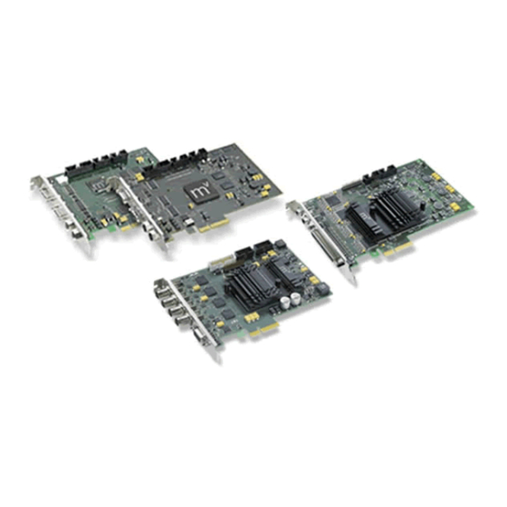
CONTENTS 6 Introduction The mvHYPERION-Series are frame grabbers for the bus system PCI Express®. The mvHYPERION frame grabber series for PCI Express® offers image processing with fast cameras using maximum capture bandwidth up to 1 G B/s. Depending on the model type, the frame grabbers are suitable for high-end machine vision applications with CameraLink cameras as well as broadcasting or surveillance solutions. -
Page 19: Quickstart
For a correct installation of the frame grabber please install the MSI package before connecting any board to the system. Afterwards you can install the physical board(s) and when the system starts again everything else is done automatically. MATRIX VISION GmbH... -
Page 20: Software Installation
7.2.2 Software installation All necessary drivers for Windows and Linux are contained in the mvIMPACT CD-ROM or DVD-ROM. For newer driver versions we recommend to visit the MATRIX VISION website at www.matrix-vision.de, section Support/ Download/Hardware. After the Hardware installation (p. 15) the boot sequence shows "Found New Hardware" and starts the Windows Hardware Wizard. - Page 21 7.2 Windows Figure 2: mvHYPERION installer - Start window Select the folder, where you want to install the software. Figure 3: mvHYPERION installer - Select folder Select the features, which you want to install. Following features exist: MATRIX VISION GmbH...
- Page 22 Visual C++ 7, Visual C++ 6 and Borland C Builder 6. The wxPropView (p. 48) project exists only for Visual C++ 7. • "Documentation" This will install this manual as single HTML help file (.chm). Figure 4: mvHYPERION installer - Select features Confirm the installation by clicking "Next". MATRIX VISION GmbH...
- Page 23 The installation process copies the files to Windows. Then Windows shows a message to signal that this driver is not checked through Microsoft. This is only an attempt to make insecure and it is recommended to ignore it. Press "Continue Anyway" and finish the driver installation. Figure 6: mvHYPERION installer - Windows logo testing MATRIX VISION GmbH...
-
Page 24: Linux
After this, you have to restart the system. Afterwards, you can acquire images with the frame grabber. Simply start the application wxPropView (p. 48) (wxPropView.exe). See also wxPropView (p. 48) 7.3 Linux 7.3.1 System Requirements Kernel requirements Kernel 2.6.x. Software requirements MATRIX VISION GmbH... -
Page 25: Installing The Mvimpact Acquire Driver
• Install the wxWidgets "wxGTK" and "wxGTK-develop" RPMs. Others that will be automatically installed due to dependencies include "wxGTK-compat" and "wxGTK-gl". Although the MATRIX VISION software does not use the ODBC database API the SuSE version of wxWidgets has been compiled with ODBC support and the RPM does not contain a dependency to automatically install ODBC. - Page 26 (p. 48). The mvIMPACT Acquire libraries look for camera definition files in the directory "mvimpact-acquire/camerafiles" so you will need to create these directories as the "root" user using "mkdir -p ./mvimpact-acquire/camerafiles" MATRIX VISION GmbH...
- Page 27 • or copying the libraries by hand to a system directory like "/usr/lib" (or using some symbolic links), • or entering the directory in "/etc/ld.so.conf" and running "ldconfig" e.g. to start the application called "LiveSnap" MATRIX VISION GmbH...
- Page 28 You will need to edit the file to fit your system. As delivered, all entries are commented out. If you do not use udev then you will have to create a device node yourself by hand. For example, you could do the following to use major device number 64: mknod /dev/hyperion c 64 0 MATRIX VISION GmbH...
-
Page 29: Connecting A Camera
"root" user using "mkdir -p /etc/matrix-vision/mvimpa You should download the camera definitions for your camera from the MATRIX VISION website and copy them to this directory. 7.4 Connecting a camera To connect a camera, for example via CameraLink cable to the mvHYPERION-CLx frame grabber, please do the following: •... - Page 30 C++ API reference, where descriptions for all properties relevant for the user (grouped together in classes sorted by topic) can be found. As wxPropView (p. 48) doesn't introduce new functionality but simply evaluates the list of features offered by the device driver and lists them any modification made using the GUI MATRIX VISION GmbH...
- Page 31 One version of the tool will always be delivered in source so it can be used as a reference to find out how to get the desired information from the device driver. MATRIX VISION GmbH...
-
Page 32: Technical Data
Normally, manufacturers of CameraLink™ cameras provide software to parameterize the camera. If this software abides by the specification, it will access our serial interface driver automatically. MATRIX VISION GmbH... - Page 33 Figure 3: mvHYPERION-CLe Figure 4: mvHYPERION-CLf 8.1.2.1 Status LEDs Figure 5: Rev. 1.x Name Description FPGA state Green: FPGA is loaded PCI Express® connection state Green: No problem with connection Figure 6: Rev. 3.x MATRIX VISION GmbH...
- Page 34 Yclk- Input 4- Yclk- Input 4- Xclk+ Input 4+ Yclk+ Input 4+ Yclk+ Input 4+ Input 5- Input 5- Input 5- Input 5+ Input 5+ Input 5+ SerTC+ Output 6+ Not used Not used, In- put 6+ MATRIX VISION GmbH...
- Page 35 Anode Green Trigger-In1 (-) - Cathode Yellow Sync-In1 (+) - Anode Gray Sync-In1 (-) - Cathode Pink GND (camera power) Blue 8.1.2.5 Pinning J4 (Camera 2: Trigger/Flash/Power) Pin. Signal Cable (KS99-0285) +12 V DC (0.7A/2A) (camera power) MATRIX VISION GmbH...
- Page 36 +3.3V out +3.3V DC power supply 9..12 GPIN0..3 LVTTL(3.3V) input. not 5V tolerant! 13..16 GPOUT0..3 LVTTL(3.3V) output. not 5V tolerant! Ground Ground +12V DC Out +12V DC power supply +12V DC Out +12V DC power supply Ground Ground MATRIX VISION GmbH...
- Page 37 TTL (5V) PLC (24V) PLC (24V) Switch S3 Switch between TTL (5V) and PLC (24V) as well as Trigger and Sync on connector J4 Position Comment Trigger (1) Sync (2) TTL (5V) TTL (5V) PLC (24V) PLC (24V) MATRIX VISION GmbH...
- Page 38 CONTENTS 8.1.2.9 Digital I/Os Figure 10: Trigger-In mvHYPERION-CLx MATRIX VISION GmbH...
- Page 39 (VIH, min = minimum input voltage, which causes an active signal) min: VIL, max (VIL, max = maximum input voltage, which causes an inactive signal) VIL, min -30V (VIL, min = minimum input voltage, which causes an active signal) MATRIX VISION GmbH...
- Page 40 (OH, mix = minimum active output voltage with Iout = -2mA output current) min: 0.4V (OL, max = maximum inactive output voltage with Iout = +2mA output current) max: Iout, (Iout, max = maximum output current) max: 8.1.2.10.3 LVTTL-OC parameters (I2C-SDA) MATRIX VISION GmbH...
-
Page 41: Components
PCIe 3.3V Max. 1A PCIe 12V Max. 0.05A + camera power Camera supply Via PCI Express® 12V max. 0.7A fused Via PCI Express® 12V max. 2A fused Via additional floppy power plug up to 2A Environmental con- ditions MATRIX VISION GmbH... -
Page 42: Device Feature And Property Lists
147 mm 155 mm Width 95 mm 111.5 mm 8.1.4 Device Feature And Property Lists 8.1.4.1 mvHYPERION-CLm 8.2 mvHYPERION-32R16 8.2.1 Block diagram The following block diagram shows schematically how the mvHYPERION-32R16 is designed. Figure 13: mvHYPERION-32R16 block diagram MATRIX VISION GmbH... -
Page 43: Connectors
FPGA state Green: FPGA is loaded 8.2.2.2 Pinning J1 (68-pol connector) Figure 15: J1 Signal Note Signal Note Power 5V GND (G) VIDEO_15 GND (G) VIDEO30 Not used GND (G) VIDEO_14 GND (G) VIDEO29 Not used GND (G) MATRIX VISION GmbH... -
Page 44: Components
Manufacturer of the connector: Nexus Part No.: 32040168R 8.2.2.3 Audio Both audio connectors (left and right) are Cinch connectors. 8.2.3 Components mvHYPERION -32R16 Video Input signal Interlaced, gray scale Interlaced, color 50Hz 60Hz NTSC Number of video inputs MATRIX VISION GmbH... -
Page 45: Mvhyperion-Hd-Sdi
Storage temperature -20 up to 70 C Humidity 10 up to 90 % non-condensing Dimensions Length 170 mm Width 111.1 mm 8.3 mvHYPERION-HD-SDI 8.3.1 Block diagram The following block diagram shows schematically how the mvHYPERION-HD-SDI is designed. MATRIX VISION GmbH... -
Page 46: Connectors
CONTENTS Figure 16: mvHYPERION-HD-SDI-2 block diagram 8.3.2 Connectors Figure 17: mvHYPERION-HD-SDI-2 8.3.2.1 Use of J1..J2 Connector usage mvHYPERION -HD-SDI-2 Camera 1 (3G/HD-SDI signal) Camera 2 (3G/HD-SDI signal) MATRIX VISION GmbH... - Page 47 Ground +5V power supply +5V DC +3.3V power supply +3.3V DC 12..9 GPIN3..0 LVTTL(3.3V) input. not 5V tolerant! 16..13 GPOUT3..0 LVTTL(3.3V) output. not 5V tolerant! Ground +12V power supply +12V DC +12V power supply +12V DC Ground MATRIX VISION GmbH...
-
Page 48: Components
Digital signals (pins 9-16) are LVTTL signals and not 5V tolerant. Failure to take this into account may result in the destruction of the board. Attention Without an additional card with corresponding snubbers these signals must not conducted! 8.3.3 Components mvHYPERION -HD-SDI-2 supported signal formats MATRIX VISION GmbH... - Page 49 Bit) ported; Level Firmware ver- sion Acquisition of 2 independent standard quired. HD-SDI signals or one standard 3G-SDI signal 720p :2:2 292- (2x10 Bit) 1080i/psf 50, host sys- :2:2 292- (2x10 puts Bit) fields gether frame. MATRIX VISION GmbH...
- Page 50 Level Firmware ver- sion quired. Acquisition of up to 2 non-standard HD/3G-SDI signals 1080p 50(100), Raw(2in1) frames 94(119. 88), 60(120) 424- dou- Level height; Only chan- sup- ported; Firmware ver- sion quired. 720p Raw(2k), Raw(12 Bit) MATRIX VISION GmbH 292-...
- Page 51 Camera supply Via PCI Express® 12V fused Environmental conditions Ambient temperature 0 up to 45 C Storage temperature -20 up to 70 C Humidity 10 up to 90 % non-condensing Dimensions Length 155 mm Width 111.1 mm MATRIX VISION GmbH...
-
Page 52: Application Usage
9.1 wxPropView wxPropView (p. 48) is an interactive GUI tool to acquire images and to configure the device and to display and modify the device properties of MATRIX VISION GmbH hardware. After the installation you can find wxPropView (p. 48) •... - Page 53 (tree control with the device settings accessible by the user) – "Display" (for the acquired images) – "Analysis" (information about whole images or an AOI) By clicking on F1 you will get the HELP dialog. Now, you can initialize a device by MATRIX VISION GmbH...
- Page 54 Once you have selected the device of your choice from the drop down menu click on the "Use" button to open it. When the device has been opened successfully, the remaining buttons of the dialog will be enabled: Note Following screenshots are representative and where made using a mvHYPERION frame grabber as the cap- turing device. MATRIX VISION GmbH...
- Page 55 • select an "Acquisition Mode" e.g. "SingleFrame" and • click the "Acquire" button. Note The techniques behind the image acquisition can be found in the developers sections. The frame rate depends on • the camera, • the pixel clock of the sensor MATRIX VISION GmbH...
- Page 56 Modified properties (even if the value is the same as the default) will be displayed in black. Figure 6: wxPropView - Storing settings MATRIX VISION GmbH...
- Page 57 • explicitly load device family specific settings from a XML file previously created ("From A File") Note With "Action - Capture Settings - Manage..." you can delete the settings which were saved on the system. Figure 7: wxPropView - Restoring settings MATRIX VISION GmbH...
- Page 58 If supported by the property, the user might increase or decrease the number of values stored by right clicking on the PARENT grid element. If the property allows the modification the pop up menu will contain additional entries now: MATRIX VISION GmbH...
- Page 59 Also the user might want to set all (or a certain range of) values for properties that store multiple values with a single operation. If supported by the property, this can also be achieved by right clicking on the PARENT grid element. If the property allows this modification the pop up menu will again contain additional entries: MATRIX VISION GmbH...
- Page 60 It's possible to either set all (or a range of) elements of the property to a certain value OR to define a value range, that then will be applied to the range of property elements selected by the user. The following example will explain how this works: Figure 12: wxPropView - Setting multiple property values within a certain value range MATRIX VISION GmbH...
- Page 61 The return value (in almost every case an error code as an integer) will be displayed in the lower right corner of the tree control. The values displayed here directly correspond the error codes defined in the interface reference and therefore will be of type TDMR_ERROR or TPROPHANDLING_ERROR. MATRIX VISION GmbH...
- Page 62 • by dragging an image file into an image display within wxPropView (p. 48) • by starting wxPropView (p. 48) from the command line passing the file to open as a command line param- eter (p. 94) (under Windows® e.g. "wxPropView.exe MyImage.png" followed by [ENTER]) MATRIX VISION GmbH...
- Page 63 . In this step by step setup wxPropView (p. 48) has been started like this from the command line: "dcy" wxPropView dcx=1 dcy=2 This will result in 1 display in horizontal direction and 2 in vertical direction. MATRIX VISION GmbH...
- Page 64 1. Various additional capture setting can be created. In order to understand what a capture setting actually is please refer to • "Working with settings" chapter of the "mvIMPACT Acquire API" manuals. Creating a capture setting is done via "Capture - Capture Settings - Create Capture Setting". MATRIX VISION GmbH...
- Page 65 Figure 19: wxPropView - Create capture setting - Choosing name 3. And finally for the base this new setting shall be derived from. Figure 20: wxPropView - Create capture setting - Choosing base Afterwards, in this example we end up having 2 capture settings: MATRIX VISION GmbH...
- Page 66 Now, to set up wxPropView (p. 48) to display all images taken using capture setting "Base" in one display and all image taken using capture setting "NewSetting1" in another display the capture settings need to be assigned to image displays via "Capture - Capture Settings - Assign To Display(s)". MATRIX VISION GmbH...
- Page 67 The minimum number of requests needed is 2 times the amount of images displays. The number of requests used by the driver can be set up in the drivers property tree: MATRIX VISION GmbH...
- Page 68 Finally, wxPropView (p. 48) must be configured in order to use all available capture settings in a round-robin scheme. This can be done by setting the capture setting usage mode to "Automatic" via "Capture - Capture Settings - Usage Mode": MATRIX VISION GmbH...
- Page 69 When only one setting shall be used at a given time, this can be achieved by setting the capture setting usage mode back to "Manual" via "Capture - Capture Settings - Usage Mode". Then the setting that shall be used can be manually selected in the request control list: MATRIX VISION GmbH...
- Page 70 (p. 48) shows snapped or live images in the display area of the GUI. The area, however, shows the most significant bits (msb) of the image in the 8 bit display. The following image shows how a mid-grey 12 bit pixel of an image is displayed with 8 bit. Additionally, two shifts are shown. MATRIX VISION GmbH...
- Page 71 View". While the first (default) view will display the device drivers feature tree in a way that might be suitable for most users of a GUI application it might present the features in a slightly different order as they actually are implemented MATRIX VISION GmbH...
- Page 72 Figure 29: Developers View 9.1.1.11 Accessing log files Since mvIMPACT Acquire 2.11.9 Using Windows, it is possible to access the log files generated by MATRIX VISION via the Help menu. Sending us the log files will speed up support cases. MATRIX VISION GmbH...
-
Page 73: How To Configure A Device
Devices belonging to this family only support the Device Specific interface layout which is the common interface layout supported by most MATRIX VISION devices. GenICam compliant devices can be operated in different interface layouts. Have a look at a GenICam compliant device for additional information. - Page 74 (Analysis tabs). Whenever an event is send by the device that updates one of the properties a callback has been attached to, the output window will print a message with some information about the detected change. MATRIX VISION GmbH...
- Page 75 "camera description" classes are supported by an individual device can be seen directly after the device has been initialised by looking in the "camera description" list. By default this list will contain one description for each supported basic family: MATRIX VISION GmbH...
- Page 76 To select a certain camera description to be used to prepare the capture device for the expected data the property "Type" under "Image Settings - Camera" can be modified. Here every available set of camera parameters will be listed: MATRIX VISION GmbH...
- Page 77 • typing the new name in the parameter edit control right of the "Copy" method of the camera description to create the copy from. • Afterwards, press ENTER to commit the new name and then the "Copy" method can be invoked • by right clicking on the name of the function and MATRIX VISION GmbH...
- Page 78 Figure 30: wxPropView - Creating a new camera description Afterwards, the newly created camera description will be added to the list of existing ones. Its parameters at this point will match the parent description (the one the "Copy" method was executed from) completely. MATRIX VISION GmbH...
- Page 79 Therefore, the next step would probably be to modify some of the parameters. Once this has been done (or before) the newly created description can be selected via the property "Type" under "Image Settings - Camera": MATRIX VISION GmbH...
- Page 80 To store a camera description permanently the "Export" method of the new camera description must be invoked. The method does not require any parameters so it can be executed directly by right clicking on the name of the function and selecting "Execute" from the popup menu: MATRIX VISION GmbH...
- Page 81 Figure 33: wxPropView - Exporting a created camera description As a direct result the modified settings will become the new default values of this particular camera description. wxPropView (p. 48) indicates this by displaying all values belonging to the description in green now: MATRIX VISION GmbH...
- Page 82 DMR_EXECUTION_PROHIBITED will be returned. When exporting a camera description a file in XML format will be written to disc. Under Windows® camera de- scriptions will be stored under "%ALLUSERS%\Documents\MATRIX VISION\mvIMPACT acquire\ which will point to the same CameraFiles"...
- Page 83 9.1 wxPropView Figure 35: wxPropView - After re-opening of the device Once a description is selected, that hasn't been in the list of camera descriptions before, it will be created and thus will become available for modifications again: MATRIX VISION GmbH...
- Page 84 After a camera has been modified the "Import" method can be used to fall back to the values stored in the camera description file: MATRIX VISION GmbH...
- Page 85 9.1 wxPropView Figure 37: wxPropView - Invoking the "Import" command of a camera description This will restore the default settings for this description: MATRIX VISION GmbH...
- Page 86 If you need a camera description (p. 71) of an unknown CameraLink or SDI camera, wxPropView (p. 48) supports you with three properties, which can be found in "Info - Camera": • DataCycleCounterLine0 • DataCycleCounterLine1 • LineCounter For line scan cameras, the property DataCycleCounterLine0 is enough to know. MATRIX VISION GmbH...
- Page 87 9.1 wxPropView Figure 39: wxPropView - Info - Camera For area scan cameras, you will need all three properties. MATRIX VISION GmbH...
- Page 88 38 are showing CameraLink examples with default values in "Camera Descriptions". The values from "Info - are not entered yet.) Camera" Note To get the current values of the properties mentioned above you have to "Acquire" a "SingleFrame" first! MATRIX VISION GmbH...
- Page 89 9.1.2.5 Basic trigger techniques in CameraLink systems 9.1.2.5.1 Area scan cameras "Mode 1: Frame grabber is triggered, free running camera" Figure 41: Frame grabber is triggered, free running camera "Mode 2: Camera is triggered" Figure 42: Camera is triggered MATRIX VISION GmbH...
- Page 90 CONTENTS 9.1.2.5.2 Line scan cameras "Mode 1: Camera is triggered by frame grabber" Figure 43: Camera is triggered by frame grabber "Mode 2: External trigger signal triggers camera" Figure 44: External trigger signal triggers camera MATRIX VISION GmbH...
- Page 91 ) and passed to the camera. In order to that, the camera acquires an image and sends it to the frame grabber. You do not need a trigger on the frame grabber for the image acquisition given that the frame grabber waits for the next image. MATRIX VISION GmbH...
- Page 92 "Trigger-In" 3. Choose the "TriggerActivation" according to the application (e.g. "FallingEdge", "RisingEdge", etc.). Per image and frame trigger, the number of lines will be acquired, which were defined in the camera description and the AOI setting before. MATRIX VISION GmbH...
- Page 93 To use StartTrigger, in wxPropView (p. 48) you have to • set "Image Settings - Camera - TriggerControls - FrameStart" to "On", • select in "FrameStart" the used "TriggerSource" and • set "Image Settings - Camera - TriggerControls - FrameStop" to "Off". MATRIX VISION GmbH...
- Page 94 In TriggerStartStop there are two trigger sources, one to start the acquisition and the second trigger event to stop it. Between start and stop, there is at least one line pause. The image height is affected by the stop event. Figure 47: TriggerStartStop MATRIX VISION GmbH...
- Page 95 • select in "FrameStop" the used "TriggerSource". Figure 48: wxPropView - Setting TriggerStartStop 9.1.2.7.3 TriggerStartStop - Restart With "TriggerStartStop - Restart" the first trigger starts the acquisition and following trigger signal stops the previ- ous acquisition and starts the next one. MATRIX VISION GmbH...
- Page 96 To use "TriggerStartStop - Restart", in wxPropView (p. 48) you have to • set the same parameters in "Image Settings - Camera - TriggerControls - FrameStart" and "Image Settings - Camera - TriggerControls - FrameStop". Figure 50: wxPropView: Setting StartTrigger MATRIX VISION GmbH...
- Page 97 With TriggerDelay it is possible to specify a delay after the trigger start event. Figure 51: TriggerDelay To use TriggerDelay, in wxPropView (p. 48) you have to • set in "CameraDescriptions" the "Y" parameter of "ActiveVideoAoi", Using line scan cameras, the "Y" position specifies the trigger acquisition delay in lines. MATRIX VISION GmbH...
-
Page 98: Command-Line Options
Will display the complete property tree (including the data not meant to be accessed by the user) in the property grid. Example (Tree will be shown) fulltree=1 device Will directly open a device with a particular serial number. will take the first device. Example: d=GX000735 MATRIX VISION GmbH... -
Page 99: Mvdeviceconfigure
This will start the first available device, will hide the Quick Setup Wizard, and will display the complete property tree. 9.2 mvDeviceConfigure mvDeviceConfigure (p. 95) is an interactive GUI tool to configure MATRIX VISION devices. It shows all connected devices. - Page 100 9.2.1.2 Step 2: Open dialog to set the ID With the device selected, select the menu item Action and click on Set ID. Note It is also possible to select the action with a right click on the device. Figure 54:mvDeviceConfigure - Select action MATRIX VISION GmbH...
-
Page 101: How To Update The Firmware
Figure 56:mvDeviceConfigure - Resolved ID conflict 9.2.2 How to update the firmware With the mvDeviceConfigure tool it is also possible to update the firmware. In the device list, new firmware versions, if available, will be marked in blue. These steps are necessary: MATRIX VISION GmbH... - Page 102 With the device selected, select the menu item Action and click on Update firmware. Note It is also possible to select the action with a right click on the device. Figure 57:mvDeviceConfigure - Select action 9.2.2.3 Step 3: Firmware file selection Select the firmware file and open it. MATRIX VISION GmbH...
- Page 103 9.2 mvDeviceConfigure Figure 58:mvDeviceConfigure - Select firmware file You will see an information dialog, which says that the firmware will take some time. Please click OK. Figure 59:mvDeviceConfigure - Select firmware file MATRIX VISION GmbH...
-
Page 104: How To Recover A Broken Firmware Update
• Update the firmware (p. 97). After reboot of the system (cold starting), the new version will be used. Note The flash update will take some time and needs processing power. During update mvDeviceConfigure (p. 95) does not respond to user input. MATRIX VISION GmbH... -
Page 105: How To Allocate Image Memory
Manager". 5. Here you have to possible modes: (a) With Automatic, the driver makes the memory management. Figure 62:wxPropView - Image Memory Manager (b) With UsePool, you can define for example the block sizes of the memory. MATRIX VISION GmbH... -
Page 106: How To Disable Cpu Sleep States A.k.a. C States ( Windows 8)
Thus in order to permanently disable the sleep states, this needs to be done for all power schemes that will be used when operating devices. 1. Start mvDeviceConfigure. 2. Go to tab "Settings" and unselect "CPU Idle States Enabled" MATRIX VISION GmbH... -
Page 107: Command-Line Options
With Windows Vista or newer mvDeviceConfigure must be started from a command shell with administrator privileges in order to modify the processors sleep states. 9.2.6 Command-line options It is possible to start mvDeviceConfigure via command line and controlling the starting behavior using parameters. The supported parameter are as follows: MATRIX VISION GmbH... - Page 108 This will update the firmware of ALL mvBlueFOX devices in the current system. mvDeviceConfigure update_fw=mvBlueFOX-2 * lf=output.txt quit This will update the firmware of ALL mvBlueFOX-2 devices in the current system, then will store a log file of the executed operations and afterwards will terminate the application. mvDeviceConfigure setid=BF000666.5 MATRIX VISION GmbH...
- Page 109 This will update the firmware of 2 mvBlueFOX cameras. mvDeviceConfigure ipv4_mask=169.254. * ;192.168.100 * update_fw=GX * This will update the firmware of all mvBlueCOUGAR-X devices with a valid IPv4 address that starts with '169.254.' or '192.168.100.'. MATRIX VISION GmbH...
-
Page 110: Hrtc - Hardware Real-Time Controller
1. a = a - 1 2. WaitClocks 50 3. Jump 0 While a > 0 The section How to use the HRTC (p. 107) should give the impression what everything can be done with the HRTC. wxPropView - Introduction: https://www.matrix-vision.com/tl_files/mv11/trainings/wxPropView/wx PropView_HRTC/index.html MATRIX VISION GmbH... -
Page 111: How To Use The Hrtc
Figure 1: wxPropView - Setting up the HRTC usage Following trigger modes can be used with HRTC: • OnLowLevel • OnHighLevel • OnFallingEdge • OnRisingEdge • OnHighExpose Further details about the mode are described in the API documentation: MATRIX VISION GmbH... - Page 112 The description for the mvIMPACT Acquire SDK for C developers is available as a separate file: mvIMPACT_ Acquire_API_C_manual.chm which is • either part of the installed package or • online from https://www.matrix-vision.com Here an online version of the documentation is available as well. MATRIX VISION GmbH...
- Page 113 The description for the mvIMPACT Acquire SDK for C++ developers is available as a separate file: mvIMPACT_ Acquire_API_CPP_manual.chm which is • either part of the installed package or • online from https://www.matrix-vision.com Here an online version of the documentation is available as well. MATRIX VISION GmbH...
- Page 114 The description for the mvIMPACT Acquire SDK for .NET developers is available as a separate file: mvIMPACT _Acquire_API_NET_manual.chm which is • either part of the installed package or • online from https://www.matrix-vision.com Here an online version of the documentation is available as well. MATRIX VISION GmbH...
- Page 115 'mvIMPACT Acquire for python' for Python versions 2.7 to 3.2: https://www.microsoft.com/en-us/download/details.aspx?id=44266 The use of this compiler packet has been tested by MATRIX VISION and it is is highly recommended. When installing the mvIMPACT Acquire Python API on a target system all files needed for building the actual extension module can be found in /mvIMPACT_Python.
- Page 116 # If you want to use this module in your code feel free to do so but make sure the ’Common’ folder resides in from Common import * # For systems with NO mvDisplay library support #import ctypes #import Image MATRIX VISION GmbH...
- Page 117 #cbuf = (ctypes.c_char * imageSize).from_address(long(req.imageData.read())) #arr = numpy.fromstring(cbuf, dtype = channelType) #arr.shape = (height, width, channelCount) #if channelCount == 1: img = Image.fromarray(arr) #else: img = Image.fromarray(arr, ’RGBA’ if alpha else ’RGB’) if pPreviousRequest != None: pPreviousRequest.unlock() MATRIX VISION GmbH...
- Page 118 The above code uses the Python 3 style print. Because of the line from __future__ import print_function This will also work with Python versions starting with version 2.6. For smaller versions of Python the code needs to be changed! MATRIX VISION GmbH...
- Page 119 15.1.6 ISpecifyPropertyPages 15.2 Logging The DirectShow_acquire logging procedure is equal to the logging of the MATRIX VISION products which uses mvIMPACT Acquire. The log output itself is based on XML. If you want more information about the logging please have a look at the Logging chapter of the respective "mvI MPACT Acquire API"...
- Page 120 . I.e. if you have installed the 32 bit version of the VLC Media Player, Virtual Dub, etc., you have to register the MV device with the 32 bit version of mvDeviceConfigure (p. 95) ("C:\Program Files\MATRIX VISION\mvIM PACT Acquire\bin") ! 15.3.1 Registering devices...
- Page 121 15.3 Registering and renaming devices for DirectShow usage Figure 2: mvDeviceConfigure - register all devices 3. After a successful registration the column "registered for DirectShow" will display 'yes' for every device and the devices will be registered with a default DirectShow friendly name. MATRIX VISION GmbH...
- Page 122 2. Now, select the device you want to rename, click the right mouse button and select "Set DirectShow friendly name": Figure 4: mvDeviceConfigure - set DirectShow friendly name 3. Then, a dialog will appear. Please enter the new name and confirm it with "OK". MATRIX VISION GmbH...
- Page 123 The following command line options are available an can be passed during the silent registration: EXAMPLES: Register ALL devices that are recognized by mvIMPACT Acquire (this will only register devices which have drivers installed). regsvr32 <path>\DirectShow_acquire.ax /s MATRIX VISION GmbH...
- Page 124 PoCL otherwise Pin 1 and Pin 26 of the CL con- nectors act like internal shields. Pseudo colors Display of gray scale images in false colors. A corresponding color is assigned to a specific gray scale value. MATRIX VISION GmbH...
- Page 125 24-bit true color; 16.7 million colors Vertical sync Synchronization pulse in video signal for field end recognition. Zero signal The zero signal was needed with the old frame grabbers, to calibrate the analog/digital converter (ADC) (signal and parameter aren't important anymore). MATRIX VISION GmbH...
- Page 126 If someone puts e.g. a periodical digital signal at the Sync-In input, this signal will be bypassed to CC1. The following Figure shows how this will look like using wxPropView (p. 48) : Figure 1: wxPropView - Digital I/O - Pass-through of a digital signal MATRIX VISION GmbH...
- Page 127 Figure 1: wxPropView - Pulse start sample • Working with an rotary encoder (p. 124) – parameters * external signals from a rotary encoder, which starts the pulse sequence initially - "Rotary Decoder" * decode the signals of the rotary encoder. MATRIX VISION GmbH...
- Page 128 During the rotation of the axis, an rotary encoder generates a so-called Gray code signal at the output of the two data lines: Figure 1: Principle of an rotary encoder Figure 2: Gray code signal at the output of the two data lines MATRIX VISION GmbH...
- Page 129 • PulseMultiplication (p. 126) • Direction (p. 126) • Mode (p. 126) • int Reset() (p. 127) 17.4.1 DigitalSignalA The first data line of the rotary encoder. 17.4.2 DigitalSignalB The second data line of the rotary encoder. MATRIX VISION GmbH...
- Page 130 • "InhibitBackwardUntilLastPos": The direction of rotation is relevant and the edge changes are counted. This means, if the direction is changed, the edges will be counted (counter initial value is 0). If the direction changes again, the counter will be decremented until 0. MATRIX VISION GmbH...
- Page 131 Basler's Sprint line scan color camera uses a two line sensor with a Bayer Mosaic filter mask. To use the demosaic algorithm correctly, you have to set the • BayerParity. There are 4 possibilities for the BayerParity: MATRIX VISION GmbH...
- Page 132 As you can see in Figure 1, there are trigger delays possible (up to an almost complete frame). The trigger start condition (TriggerActivation) can be set via wxPropView (p. 48) in "Setting - Base - Camera - TriggerControls". In Figure 2, the start condition is a RisingEdge at the J4 connector. MATRIX VISION GmbH...
- Page 133 The following sections show how you have to set the mvHYPERION according to the different modes. 17.5.2 RawLineAcquisition Mode In this mode, the camera sends the color lines alternately. For more details about this mode, please have a look at the camera's manual. MATRIX VISION GmbH...
- Page 134 All further FrameSync signals are ignored. This mode is required with Basler's sprint cameras. The camera line synchronization in this sample is a FallingEdge at Sync-In. Afterwards using PulseStart Configuration0, a FallingEdge SinglePulse signal is generated at digital out CC1: MATRIX VISION GmbH...
- Page 135 "red" or a raw "blue" pixel value (for more details please have a look at the camera's manual). In sum, you can say that this is a double exposure of the same line. For this, you will need a pulse multiplication. MATRIX VISION GmbH...
- Page 136 CONTENTS Figure 5: wxPropView - Settings Height (H), Format BayerPacked, BayerParity, ScanMode, line scanStartCondition It only makes sense to reproduce this application using a rotary encoder (p. 124). The application could look like this: MATRIX VISION GmbH...
- Page 137 17.5 Working with a Basler Sprint line scan color camera Figure 6: Conveyor belt with rotary decoder The camera line synchronization in this sample is the trigger signal of a rotary encoder. Afterwards, two SinglePulse signals are sent via digital out CC1: MATRIX VISION GmbH...
- Page 138 CONTENTS Figure 7: wxPropView - Triggered acquisition with area-scan cameras Note With the property "Divider" you can set if every signal (or every second, third etc.) from the rotary encoder is used. MATRIX VISION GmbH...
- Page 139 • FrameStart + FrameStop (with restart option using the same event) (p. 138) The three modes will be described on the basis of a trigger event on J3. Please open "Setting - Base - Camera - TriggerControls", where you can manage the mentioned trigger events. MATRIX VISION GmbH...
- Page 140 While the frame is not finished, other trigger events are ignored. Figure 2: Trigger example It is also possible to define a trigger delay via • "TriggerDelayAbs_us" • "TriggerDelayLines" , which only makes sense using line scan cameras. Figure 3: wxPropView - Possible trigger sources MATRIX VISION GmbH...
- Page 141 Figure 7 shows an example definition, where the FrameStart is on a rising edge of J3 and FrameStop is on a falling edge of J4. MATRIX VISION GmbH...
- Page 142 The amount of lines will be available as result or image information. You have to select the same parameters using the same event in "FrameStart" "FrameStop" to activate this mode. MATRIX VISION GmbH...
- Page 143 17.6.3 AcquisitionStart Some cameras like line scan cameras send as a signal for "FrameValid" "LineValid" "FrameStart" Anyway, it is necessary to have the possibility to set the start of the acquisition. This can be done using " AcquisitionStart" MATRIX VISION GmbH...
- Page 144 Activation" e.g. "FallingEdge". This means that the FrameStart will start after a falling edge from the HRTC. Figure 1: wxPropView - TriggerSource 2. Then, you have to set the "Digital I/O - Digital Outputs - ControlMode" to "HardwareRealTime Controller" MATRIX VISION GmbH...
- Page 145 (a) Wait for an "Off" signal at the digital input (in this sample at position 9 which is DigIn0; Figure 4). (b) Wait for an "On" signal at the digital input (in this sample at position 9 which is DigIn0; Figure 4). MATRIX VISION GmbH...
- Page 146 Figure 4: wxPropView - Digital I/O - HardwareRealTimeController (c) Then, a pulse signal is set to "On" at the "TriggerController" (in this sample at position 9 which is shown in the help window). (d) Afterwards, the pulse signal is "Off" again. MATRIX VISION GmbH...
- Page 147 Figure 5: wxPropView - Digital I/O - HardwareRealTimeController (e) Finally, the program jumps back to step 0. 4. Now, if you have a rotary encoder and you have connected the signal A to the "Sync-In", you can bypass this signal, for example, to CC1: MATRIX VISION GmbH...
- Page 148 • the "TriggerSource" set to "HRTCtrl_0", • the "TriggerMode" to "On" and • the "TriggerActivation" set to "FallingEdge", as shown in Figure 2 for the "Base" setting, both cameras will capture an image at the same time. MATRIX VISION GmbH...
Need help?
Do you have a question about the mvHYPERION-Series and is the answer not in the manual?
Questions and answers