
Related Manuals for Nexcom NIFE 103


Summary of Contents for Nexcom NIFE 103
- Page 1 NEXCOM International Co., Ltd. IoT Automation Solutions Business Group PC-based Factory Automation System NIFE 103 User Manual NEXCOM International Co., Ltd. www.nexcom.com Published September 2017...
-
Page 2: Table Of Contents
24V DC Power Input ..............17 Top View .....................5 Internal Connectors ................18 Bottom View ..................5 BIOS Flash Pin Header ..............18 Mechanical Dimensions ................6 Power Button Connector ..............18 Copyright © 2017 NEXCOM International Co., Ltd. All Rights Reserved. NIFE 103 User Manual... - Page 3 Security .....................42 Boot ....................42 Save & Exit ..................43 Appendix A: Power Consumption ......44 Appendix B: Watchdog Timer Programming Reference ...45 Appendix C: GPI/O Programming Guide ....46 Copyright © 2017 NEXCOM International Co., Ltd. All Rights Reserved. NIFE 103 User Manual...
-
Page 4: Preface
Acknowledgements The product(s) described in this manual complies with all applicable NIFE 103 is a trademark of NEXCOM International Co., Ltd. All other product European Union (CE) directives if it has a CE marking. For computer systems names mentioned herein are registered trademarks of their respective to remain CE compliant, only CE-compliant parts may be used. -
Page 5: Rohs Compliance
(Cr6+) < 0.1% or 1,000ppm, Polybrominated biphenyls (PBB) < 0.1% or 1,000ppm, and Polybrominated diphenyl Ethers (PBDE) < 0.1% or 1,000ppm. In order to meet the RoHS compliant directives, NEXCOM has established an engineering and manufacturing task force to implement the introduction of green products. -
Page 6: Warranty And Rma
(manuals, cable, etc.) and any components from the card, such as CPU and RAM. If the components were suspected as part of the problems, ▪ If RMA goods can not be repaired, NEXCOM will return it to the customer please note clearly which components are included. Otherwise, NEXCOM without any charge. - Page 7 ESD workstation. If no such station is available, you can provide some ESD protection by wearing an antistatic wrist strap and attaching it to a metal part of the computer chassis. Copyright © 2017 NEXCOM International Co., Ltd. All Rights Reserved. NIFE 103 User Manual...
-
Page 8: Safety Information
There is a danger of explosion if battery is incorrectly replaced. Replace only with the same or equivalent type recommended by the manufacturer. Discard used batteries according to the manufacturer’s instructions. viii Copyright © 2017 NEXCOM International Co., Ltd. All Rights Reserved. NIFE 103 User Manual... -
Page 9: Safety Precautions
RECOMMENDED BY THE MANUFACTURER. DISCARD USED BATTERIES ACCORDING TO THE MANUFACTURER’S INSTRUCTIONS. 10. All cautions and warnings on the equipment should be noted. Copyright © 2017 NEXCOM International Co., Ltd. All Rights Reserved. NIFE 103 User Manual... -
Page 10: Technical Support And Assistance
Preface Technical Support and Assistance Conventions Used in this Manual 1. For the most updated information of NEXCOM products, visit NEXCOM’s Warning: website at www.nexcom.com. Information about certain situations, which if not observed, can cause personal injury. This will prevent injury to yourself 2. -
Page 11: Global Service Contact Information
13F, No.920, Chung-Cheng Rd., ZhongHe District, Beijing, 100094, China New Taipei City, 23586, Taiwan, R.O.C. Tel: +86-10-5704-2680 Tel: +886-2-8226-7796 Fax: +86-10-5704-2681 Fax: +886-2-8226-7792 Email: sales@nexcom.cn Email: sales@nexcom.com.tw www.nexcom.cn www.nexcom.com.tw Copyright © 2017 NEXCOM International Co., Ltd. All Rights Reserved. NIFE 103 User Manual... - Page 12 Hui Yin Ming Zun Building Room 1108, Building No. 11, 599 Yunling Road, Putuo District, Shanghai, 200062, China Tel: +86-21-6125-8282 Fax: +86-21-6125-8281 Email: frankyang@nexcom.cn www.nexcom.cn Copyright © 2017 NEXCOM International Co., Ltd. All Rights Reserved. NIFE 103 User Manual...
-
Page 13: Package Contents
Preface Package Contents Before continuing, verify that the NIFE 103 package that you received is complete. Your package should have all the items listed in the following table. Item Part Number Description 19J70010300X0 NIFE 103 ASSY 6012200052X00 PE Zipper Bag #8... -
Page 14: Ordering Information
Preface Ordering Information The following information below provides ordering information for NIFE 103. NIFE 103 System (P/N: 10J70010300X0) Intel Atom processor E3826 dual core fanless system ® • 24V, 60W AC/DC power adapter w/o power cord (P/N: 7400060033X00) Copyright © 2017 NEXCOM International Co., Ltd. All Rights Reserved. -
Page 15: Chapter 1: Product Introduction
▪ 1 x Half size mini-PCIe socket for optional Wi-Fi module ▪ 1 x RS232/485 with auto flow control ▪ Support -5~50 °C operating temperature Bottom View ▪ Support +24VDC input ±20% Copyright © 2017 NEXCOM International Co., Ltd. All Rights Reserved. NIFE 103 User Manual... -
Page 16: Hardware Specifications
▪ Relative humidity: 10% to 93% (non-condensing) ▪ Shock protection: ▪ 1 x 4-in/4-out 5V GPIO via 10-pin terminal block – mSATA/eMMC: 50G, half sine, 11ms, IEC60068-27 Copyright © 2017 NEXCOM International Co., Ltd. All Rights Reserved. NIFE 103 User Manual... - Page 17 Support OS ▪ Windows 8, 32-bit/64-bit ▪ Windows Embedded Standard 8, 32-bit/64-bit ▪ Windows 7, 32-bit/64-bit ▪ Windows Embedded Standard 7, 32-bit/64-bit ▪ Linux Kernel version 3.8.0 Copyright © 2017 NEXCOM International Co., Ltd. All Rights Reserved. NIFE 103 User Manual...
-
Page 18: Knowing Your Nife 103
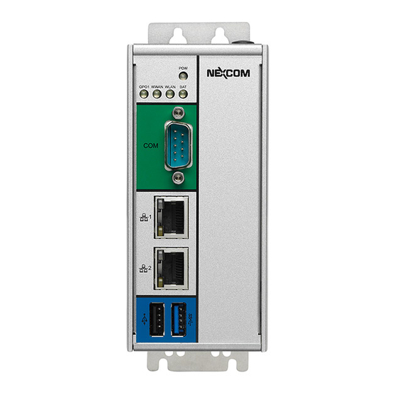
Port USB 2.0 and USB 3.0 Ports USB 2.0 and USB 3.0 ports to connect the system with USB devices. LAN1 LAN2 USB 2.0 USB 3.0 Copyright © 2017 NEXCOM International Co., Ltd. All Rights Reserved. NIFE 103 User Manual... -
Page 19: Top View
Reset The GPIO connector supports 4 digital input and 4 digital output. 24V DC Input Used to plug a DC power cord. GPIO 24V DC Input Copyright © 2017 NEXCOM International Co., Ltd. All Rights Reserved. NIFE 103 User Manual... -
Page 20: Mechanical Dimensions
Chapter 1: Product Introduction Mechanical Dimensions 56.50 106.00 18.00 100.00 3.60 3.60 30.00 Copyright © 2017 NEXCOM International Co., Ltd. All Rights Reserved. NIFE 103 User Manual... -
Page 21: Chapter 2: Jumpers And Connectors
Static electricity can damage many of the electronic ▪ Use correct screws and do not over tighten screws. components. Humid environments tend to have less static electricity than Copyright © 2017 NEXCOM International Co., Ltd. All Rights Reserved. NIFE 103 User Manual... -
Page 22: Jumper Settings
(on) and open (off). Two-Pin Jumpers: Open (Left) and Short (Right) Three-Pin Jumpers: Pins 1 and 2 are Short Copyright © 2017 NEXCOM International Co., Ltd. All Rights Reserved. NIFE 103 User Manual... -
Page 23: Nife 103 System Components
Chapter 2: Jumpers and Connectors NIFE 103 System Components The NIFE 103 system is made up of a NTIB 100 motherboard and a power board. This chapter lists the location and pinout assignment of the jumpers and connectors on each component. -
Page 24: Bottom View
Chapter 2: Jumpers and Connectors The figure below is the bottom view of the NTIB 100 motherboard. Bottom View JFW1 Copyright © 2017 NEXCOM International Co., Ltd. All Rights Reserved. NIFE 103 User Manual... -
Page 25: Connector Locations For The Power Board
Chapter 2: Jumpers and Connectors Connector Locations for the Power Board DC 24V Copyright © 2017 NEXCOM International Co., Ltd. All Rights Reserved. NIFE 103 User Manual... -
Page 26: Dip Switches
Clear CMOS Select Connector type: 2-pin On/Off DIP switch Connector type: 2-pin On/Off DIP switch Connector location: SW3 Connector location: SW2 Function Function AT_ATX_SELECT RTC_TEST# SRTC_RST# *GND *GND Copyright © 2017 NEXCOM International Co., Ltd. All Rights Reserved. NIFE 103 User Manual... -
Page 27: Connector Pin Definitions
Power LED Indicator GPO1/WWAN/WLAN/BAT LED Indicators Connector location: LED3 Connector location: LED2 GPO1 WWAN WLAN Definition Definition Definition VCC3 3VSB BATTERY_LED VCC3 WLAN_LED VCC3 WWLAN_LED VCC3 GPO_LED2 Copyright © 2017 NEXCOM International Co., Ltd. All Rights Reserved. NIFE 103 User Manual... -
Page 28: Com1 Connector
100Mbps network link 10Mbps or no link RS485_D-_R COM1_RXD COM1_TXD RS485_D+_R COM1_RTS# COM1_CTS# Definition Definition LAN2TXDP0 LAN2TXDN0 LAN2TXDP1 LAN2TXDP2 LAN2TXDN2 LAN2TXDN1 LAN2TXDP3 LAN2TXDN3 LAN2_LED_ACT# LAN2_ACTPW LAN2_LED_LINK1G# LAN2_LINK Copyright © 2017 NEXCOM International Co., Ltd. All Rights Reserved. NIFE 103 User Manual... -
Page 29: Lan2 Port
10Mbps or no link 5VSB SOC_USB0N SOC_USB0P USB3_RX0_N_C USB3_RX0_P_C USB3_TX0_N_C Definition Definition USB3_TX0_P_C 5VSB LANTXDP0 LANTXDN0 SOC_USB2N SOC_USB2P LANTXDP1 LANTXDP2 LANTXDN2 LANTXDN1 LANTXDP3 LANTXDN3 LAN_LED_ACT# LAN1_ACTPW LAN_LED_LINK1G# LAN1_LINK Copyright © 2017 NEXCOM International Co., Ltd. All Rights Reserved. NIFE 103 User Manual... -
Page 30: Micro Hdmi
Connector location: SW1 Connector location: CN8 Definition Definition Definition Definition HDMI_HPD_R PM_RESET#_J PM_RESET#_J HDMI_DATA2_P_C HDMI_DATA2_N_C HDMI_DATA1_P_C HDMI_DATA1_N_C HDMI_DATA0_P_C HDMI_DATA0_N_C HDMI_CLK_P_C HDMI_CLK_N_C HDMI_CTRL_CLK HDMI_CTRL_DAT HDMI_PWR CHASSIS_DP_GND CHASSIS_DP_GND CHASSIS_DP_GND CHASSIS_DP_GND Copyright © 2017 NEXCOM International Co., Ltd. All Rights Reserved. NIFE 103 User Manual... -
Page 31: Gpio Connector
Connector type: 1x3 3-pin terminal block Connector location: CN1 Connector location: PW1 Definition Definition Definition VCC5 VIN_1 ICH_GPI0_IN ICH_GPI1_IN VIN_VSS ICH_GPI2_IN ICH_GPI3_IN R_GND ICH_GPO0_OUT ICH_GPO1_OUT ICH_GPO2_OUT ICH_GPO3_OUT Copyright © 2017 NEXCOM International Co., Ltd. All Rights Reserved. NIFE 103 User Manual... -
Page 32: Internal Connectors
Connector type: 2x3 6-pin header, 2.0mm pitch Connector type: 1x3 3-pin header, 1.25mm pitch Connector location: JFW1 Connector location: J6 Definition Definition Definition VSPI BIOS_SPI_CS#0 BIOS_SPI_CLK EC_PWRBT# BIOS_SPI_SO BIOS_SPI_SI S3_OUT Copyright © 2017 NEXCOM International Co., Ltd. All Rights Reserved. NIFE 103 User Manual... -
Page 33: Chapter 3: System Setup
1. Remove the screws on the side chassis. 2. Remove the screws on the bottom chassis. Copyright © 2017 NEXCOM International Co., Ltd. All Rights Reserved. NIFE 103 User Manual... - Page 34 Chapter 3: System Setup 3. Remove the screws on the rear chassis. 4. Gently lift up the cover. Copyright © 2017 NEXCOM International Co., Ltd. All Rights Reserved. NIFE 103 User Manual...
-
Page 35: Installing A Msata Or 3G Module
1. Locate the mini-PCIe slot for 3G or mSATA modules. The SIM card is located in the middle of the mini-PCIe slot. until the gold-plated connector on the edge of the module completely disappears into the slot. Mini-PCIe slot Copyright © 2017 NEXCOM International Co., Ltd. All Rights Reserved. NIFE 103 User Manual... - Page 36 3. When installing a 3G module, make sure to install the SIM card first. 4. Push the module down and secure it with screws. Ensure both screws are fixed tightly to the slot. SIM card slot Copyright © 2017 NEXCOM International Co., Ltd. All Rights Reserved. NIFE 103 User Manual...
-
Page 37: Installing A Wi-Fi Module
Insert the Wi-Fi module into the slot at 45 degree angle until the gold- fixed tightly to the slot. plated connector on the edge of the module completely disappears into the slot. Half-size mini-PCIe slot Copyright © 2017 NEXCOM International Co., Ltd. All Rights Reserved. NIFE 103 User Manual... -
Page 38: Installing An Antenna
2. Locate the antenna hole on the front panel and insert the antenna jack through the antenna hole. Fix the antenna jack with ring 1 then ring 2. Ring 1 Ring 2 Copyright © 2017 NEXCOM International Co., Ltd. All Rights Reserved. NIFE 103 User Manual... - Page 39 Chapter 3: System Setup 3. Connect an external antenna to the antenna jack. Copyright © 2017 NEXCOM International Co., Ltd. All Rights Reserved. NIFE 103 User Manual...
-
Page 40: Chapter 4: Bios Setup
This chapter describes how to use the BIOS setup program for NIFE 103. The The settings made in the setup program affect how the computer performs. BIOS screens provided in this chapter are for reference only and may change It is important, therefore, first to try to understand all the setup options, and if the BIOS is updated in the future. -
Page 41: Default Configuration
Powering on the computer and immediately pressing <Del> allows you to enter Setup. Load optimized default values. Press the key to enter Setup: Saves and exits the Setup program. Press <Enter> to enter the highlighted sub-menu Copyright © 2017 NEXCOM International Co., Ltd. All Rights Reserved. NIFE 103 User Manual... - Page 42 When “” appears on the left of a particular field, it indicates that a submenu which contains additional options are available for that field. To display the submenu, move the highlight to that field and press Copyright © 2017 NEXCOM International Co., Ltd. All Rights Reserved. NIFE 103 User Manual...
-
Page 43: Bios Setup Utility
System Date [Tue 08/29/2017] F2: Previous Values System Time [15:53:09] F3: Optimized Defaults F4: Save & Exit ESC: Exit Version 2.16.1242. Copyright (C) 2013 American Megatrends, Inc. Copyright © 2017 NEXCOM International Co., Ltd. All Rights Reserved. NIFE 103 User Manual... -
Page 44: Advanced
Select the highest ACPI sleep state the system will enter when the suspend Version 2.16.1242. Copyright (C) 2013 American Megatrends, Inc. button is pressed. The options are Suspend Disabled and S3 (Suspend to RAM). Copyright © 2017 NEXCOM International Co., Ltd. All Rights Reserved. NIFE 103 User Manual... - Page 45 Super IO Chip Serial Port Enables or disables the serial port. Displays the Super I/O chip used on the board. RS485 AUTO Enables or disables RS485 Auto. Copyright © 2017 NEXCOM International Co., Ltd. All Rights Reserved. NIFE 103 User Manual...
- Page 46 Version 2.16.1242. Copyright (C) 2013 American Megatrends, Inc. CPU temperature(DTS) Detects and displays the current CPU temperature. System temperature Detects and displays the current system temperature. 12VSB Detects and displays 12V voltage. Copyright © 2017 NEXCOM International Co., Ltd. All Rights Reserved. NIFE 103 User Manual...
- Page 47 Redirection Settings will be available. Selects the serial port transmission speed. The speed must match the other side. Long or noisy lines may require a lower speed. Copyright © 2017 NEXCOM International Co., Ltd. All Rights Reserved. NIFE 103 User Manual...
- Page 48 Windows, this problem may occur. To avoid this problem, enable Redirection After BIOS POST this field to limit the return value to 3 or lesser than 3. Enables or disables redirection after BIOS POST. Copyright © 2017 NEXCOM International Co., Ltd. All Rights Reserved. NIFE 103 User Manual...
- Page 49 +/-: Change Opt. F1: General Help F2: Previous Values F3: Optimized Defaults F4: Save & Exit ESC: Exit Version 2.16.1242. Copyright (C) 2013 American Megatrends, Inc. Copyright © 2017 NEXCOM International Co., Ltd. All Rights Reserved. NIFE 103 User Manual...
- Page 50 Enables or disables SATA port 0 and SATA port 1. SATA Port1 Hotplug and SATA Port2 Hotplug Enables or disables hotplug support on SATA port 1 and SATA port 2. Copyright © 2017 NEXCOM International Co., Ltd. All Rights Reserved. NIFE 103 User Manual...
- Page 51 SCC eMMC 4.5 DDR50 Support Enables or disables SCC eMMC 4.5 DDR50 support. SCC eMMC 4.5 HS200 Support Enables or disables SCC eMMC 4.5 HS200 support. Copyright © 2017 NEXCOM International Co., Ltd. All Rights Reserved. NIFE 103 User Manual...
- Page 52 CSM Support Enables or disables CSM support. Network Controls the execution of UEFI and legacy PXE OpROM. Onboard LAN PXE Enables or disables onboard LAN PXE ROM. Copyright © 2017 NEXCOM International Co., Ltd. All Rights Reserved. NIFE 103 User Manual...
- Page 53 This is a workaround for OSs that does not support XHCI hand-off and EHCI hand-off. The XHCI and EHCI ownership change should be claimed by the XHCI and EHCI driver respectively. Copyright © 2017 NEXCOM International Co., Ltd. All Rights Reserved. NIFE 103 User Manual...
-
Page 54: Chipset
Version 2.16.1242. Copyright (C) 2013 American Megatrends, Inc. High Precision Timer Enables or disables the high precision event timer. Version 2.16.1242. Copyright (C) 2013 American Megatrends, Inc. Copyright © 2017 NEXCOM International Co., Ltd. All Rights Reserved. NIFE 103 User Manual... - Page 55 Enables or disables PCH USB rate matching hubs mode. USB EHCI Debug Enables or disables PCH EHCI debug capability. USB Power State in S5 Configures the USB power state in S5. Copyright © 2017 NEXCOM International Co., Ltd. All Rights Reserved. NIFE 103 User Manual...
-
Page 56: Security
Fast Boot When enabled, the BIOS will shorten or skip some check items during POST. This will decrease the time needed to boot the system. Copyright © 2017 NEXCOM International Co., Ltd. All Rights Reserved. NIFE 103 User Manual... -
Page 57: Save & Exit
<Enter>. You may be prompted to confirm again before exiting. Restore Defaults To restore the BIOS to default settings, select this field then press <Enter>. A dialog box will appear. Confirm by selecting Yes. Copyright © 2017 NEXCOM International Co., Ltd. All Rights Reserved. NIFE 103 User Manual... -
Page 58: Appendix A: Power Consumption
State Mode 0.071A 1.7W Keyboard & Mouse Memory: MICRON: MTFC16GAKAECN-2M (S3) 2G WT Device Under Test 100% Full Loading 0.725A 17.4W DUT: NIFE 103 SYS#1 Mode Copyright © 2017 NEXCOM International Co., Ltd. All Rights Reserved. NIFE 103 User Manual... -
Page 59: Appendix B: Watchdog Timer Programming Reference
;Setup WDT time-out value, the unit is minute. this demo code is used to program the time-out value with 1 min. SmbusWriteByte(0xE3,0x01); ;enable Soft Watch Dog Timer SmbusWriteByte(0xE0,0x55); Copyright © 2017 NEXCOM International Co., Ltd. All Rights Reserved. NIFE 103 User Manual... -
Page 60: Appendix C: Gpi/O Programming Guide
GPI/O (General Purpose Input/Output) pins are provided for custom system design. This appendix provides definitions and its default setting for the ten GPI/O pins in NIFE 103. The pin definition is shown in the following table: PowerOn PowerOn Address... - Page 61 SmbusWriteByte (0xEA, XXXX1XXXb) #define GPOC2_LO SmbusWriteByte (0xEA, XXXX0XXXb) #define GPOC1_HI SmbusWriteByte (0xEA, XXX1XXXXb) #define GPOC1_LO SmbusWriteByte (0xEA, XXX0XXXXb) void main(void) GPO7_HI; GPO8_LO; GPO9_HI; GPO10_LO; GPOC2_HI; GPOC1_LO; Copyright © 2017 NEXCOM International Co., Ltd. All Rights Reserved. NIFE 103 User Manual...
Need help?
Do you have a question about the NIFE 103 and is the answer not in the manual?
Questions and answers