
Related Manuals for Nexcom NICE 3150 Series


Summary of Contents for Nexcom NICE 3150 Series
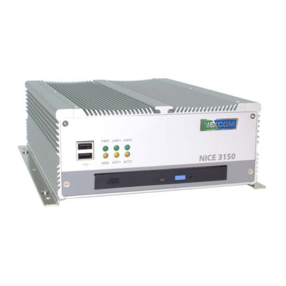
- Page 1 The Digital Infrastructure Ultra Compact Embedded System NICE 3150 Series Installation Guide...
-
Page 2: Handling Precautions
Handling Precautions 1. Always disconnect the unit from the power outlet whenever you are installing or fixing a component inside the chassis. 2. If possible, always wear a grounded wrist strap when you are installing or fixing a component inside the chassis. Alternatively, discharge any static electricity by touching the bare metal chassis of the unit case, or the bare metal body of any other grounded appliance. - Page 3 Device: * Two 184-pin DDR DIMM Support Max up to 2GB * On board Compact Flash socket x 1 * Internal 2.5”HDD Drive bay x 1 Slim DVD Combo: *CD-RW+DVD Combo 24W/10E/24R + 8D Front I/O Ports: * Optional customized logo * HDD access/Power/LAN status LED * USB 2.0 x 2 ports Rear I/O Ports:...
- Page 4 Opening Top Cover Step 1: Remove 6 screws from the top. Installing/Removing CPU Step 2: Unscrew 6 screws on heat sink Step 2.1: Pay attentions to CPU installation Step 2.2: Be aware that the beveled Step 2.3: Secure the CPU corner of the CPU as shown in the picture is aligned to the direction of the socket.
- Page 5 Step 2.4: Insert heat sink silicon Step 2.5: Lock the heat sink with screw compound Installing/Removing RAM Card Closing Top Cover Step 3: Insert either 1 or 2 DDR Step 4: Secure the top cover with screws Open Bottom Cover Step 5: Remove the screws on the bottom side NICE 3150 installation guide...
- Page 6 Installing HDD Step 6: Unscrew HDD stand Step 6.1: Secure 2.5” HDD Step 6.2: Place finished stand with HDD back to the chassis and make sure it is properly secured. Plug HDD cable and pay attention to pin1 of cable (pin1 is indicated in red).
Need help?
Do you have a question about the NICE 3150 Series and is the answer not in the manual?
Questions and answers