
Related Manuals for Nexcom Neu-X101


Summary of Contents for Nexcom Neu-X101
- Page 1 NEXCOM International Co., Ltd. Intelligent Platform & Services Business Unit Edge Computing System Neu-X101 User Manual NEXCOM International Co., Ltd. www.nexcom.com Published March 2022...
-
Page 2: Table Of Contents
Disclaimer ....................iv Precautions ....................6 Acknowledgements ................iv Jumper Settings ..................7 Regulatory Compliance Statements ............iv Locations of the Jumpers and Connectors for Neu-X101 ......8 Declaration of Conformity ..............iv Top View .....................8 RoHS Compliance ................... v Bottom View ..................9 Warranty and RMA ................ - Page 3 When to Configure the BIOS ..............29 Default Configuration ................30 Entering Setup ..................30 Legends ....................30 BIOS Setup Utility ..................32 Main ....................32 Advanced ..................33 Security .....................42 Boot ....................43 Save & Exit ..................44 Copyright © 2021 NEXCOM International Co., Ltd. All Rights Reserved. Neu-X101 User Manual...
-
Page 4: Preface
No describes how to keep the system CE compliant. part of this manual may be reproduced, copied, translated or transmitted in any form or by any means without the prior written consent from NEXCOM Declaration of Conformity International Co., Ltd. -
Page 5: Rohs Compliance
(Cr6+) < 0.1% or 1,000ppm, Polybrominated biphenyls (PBB) < 0.1% or 1,000ppm, and Polybrominated diphenyl Ethers (PBDE) < 0.1% or 1,000ppm. In order to meet the RoHS compliant directives, NEXCOM has established an engineering and manufacturing task force to implement the introduction of green products. -
Page 6: Warranty And Rma
“NEXCOM RMA Service Form” for the RMA number apply process. ▪ If RMA goods can not be repaired, NEXCOM will return it to the customer without any charge. ▪ Customers can send back the faulty products with or without accessories (manuals, cable, etc.) and any components from the card, such as CPU... - Page 7 ESD workstation. If no such station is available, you can provide some ESD protection by wearing an antistatic wrist strap and attaching it to a metal part of the computer chassis. Copyright © 2021 NEXCOM International Co., Ltd. All Rights Reserved. Neu-X101 User Manual...
-
Page 8: Safety Information
There is a danger of explosion if battery is incorrectly replaced. Replace only with the same or equivalent type recommended by the manufacturer. Discard used batteries according to the manufacturer’s instructions. viii Copyright © 2021 NEXCOM International Co., Ltd. All Rights Reserved. Neu-X101 User Manual... -
Page 9: Safety Precautions
UL/IEC 60950-1 and/or UL/IEC 62368-1. If further assistance is needed, please contact NEXCOM International Co., Ltd. (UL file owner or brand owner) for further information. Copyright © 2021 NEXCOM International Co., Ltd. All Rights Reserved. -
Page 10: Technical Support And Assistance
Preface Technical Support and Assistance Conventions Used in this Manual 1. For the most updated information of NEXCOM products, visit NEXCOM’s Warning: website at www.nexcom.com. Information about certain situations, which if not observed, can cause personal injury. This will prevent injury to yourself 2. -
Page 11: Global Service Contact Information
16F, No.250, Sec.2, Chongde Rd., Tel: +886-2-8226-7786 Tel: +886-2-8976-3077 Beitun District, Fax: +886-2-8226-7782 Email: sales@diviotec.com Taichung City, 406, Taiwan, R.O.C. Email: services@tmrtek.com www.diviotec.com Tel: +886-4-2249-1179 www.tmrtek.com Fax: +886-4-2249-1172 Email: jacobhuang@nexaiot.com www.nexaiot.com Copyright © 2021 NEXCOM International Co., Ltd. All Rights Reserved. Neu-X101 User Manual... - Page 12 9F, Tamachi Hara Bldg., LongGang District, 4-11-5, Shiba Minato-ku, ShenZhen, 518112, China Tokyo, 108-0014, Japan Tel: +86-755-8364-7768 Tel: +81-3-5419-7830 Fax: +86-755-8364-7738 Fax: +81-3-5419-7832 Email: steveyang@nexcom.com.tw Email: sales@nexcom-jp.com www.nexcom.cn www.nexcom-jp.com Copyright © 2021 NEXCOM International Co., Ltd. All Rights Reserved. Neu-X101 User Manual...
-
Page 13: Package Contents
Preface Package Contents Before continuing, verify that the Neu-X101 package that you received is complete. Your package should have all the items listed in the following table. Item Part Number Name Description 10W10X10100X0 Neu-X101 System Fanless Box PC, 3.5” Board, J3455 5060200184X00 Thermal Pad for Memory Thermal Pad E-LIN 60x20x1.5mm S35 K=2.0w/mk... -
Page 14: Ordering Information
AI Booster Card AIBooster®-X1 (P/N: 88W10X10000X0) Intel® Movidius™ Myriad™ X VPU, mini-PCIe module (1 x MA2485) AIBooster®-X2 (P/N: 88W10X10001X0) Intel® Movidius™ Myriad™ X VPU, mini-PCIe module (2 x MA2485) Copyright © 2021 NEXCOM International Co., Ltd. All Rights Reserved. Neu-X101 User Manual... -
Page 15: Chapter 1: Product Introduction
▪ Support power input 12 VDC ▪ Fanless design ▪ 1 x DDR3L up to 8GB, M.2 2242 Key M for storage device ▪ Mini-PCIe slot supports Wi-Fi and LTE module Copyright © 2021 NEXCOM International Co., Ltd. All Rights Reserved. Neu-X101 User Manual... -
Page 16: Hardware Specifications
▪ CE (EMC EN55035 + EN55032) ▪ 1 x TPM module connector ▪ FCC Class A (EMI Part 15B) ▪ 1 x Line-out audio connector ▪ LVD (EN62368-1) Copyright © 2021 NEXCOM International Co., Ltd. All Rights Reserved. Neu-X101 User Manual... - Page 17 Chapter 1: Product Introduction Dimensions ▪ 155mm (W) x 106mm (D) x 37mm (H) Operating System ▪ Windows 10 64-bit ▪ Linux 4.1 Copyright © 2021 NEXCOM International Co., Ltd. All Rights Reserved. Neu-X101 User Manual...
-
Page 18: Physical Features
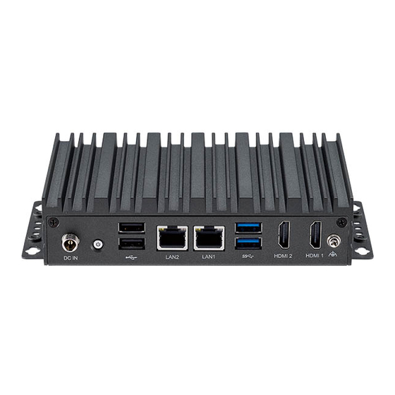
Chapter 1: Product Introduction Physical Features Front Panel Rear Panel Power Button Antenna Hole Storage LED USB 2.0 LAN2 LAN1 USB 3.0 DC Input HDMI2 HDMI1 Antenna Hole Copyright © 2021 NEXCOM International Co., Ltd. All Rights Reserved. Neu-X101 User Manual... -
Page 19: Mechanical Dimensions
Chapter 1: Product Introduction Mechanical Dimensions #6-32_NUT Ø Ø 179.5 Copyright © 2021 NEXCOM International Co., Ltd. All Rights Reserved. Neu-X101 User Manual... -
Page 20: Chapter 2: Jumpers And Connectors
2: J haPter umPers and onneCtors This chapter lists the locations of the jumpers and connectors for Neu-X101. Before You Begin Precautions ▪ Ensure you have a stable, clean working environment. Dust and dirt can Computer components and electronic circuit boards can be damaged by get into components and cause a malfunction. -
Page 21: Jumper Settings
Refer to the illustrations below for examples of what the 2-pin and 3-pin jumpers look like when they are short (on) and open (off). Two-Pin Jumpers: Open (Left) and Short (Right) Three-Pin Jumpers: Pins 1 and 2 are Short Copyright © 2021 NEXCOM International Co., Ltd. All Rights Reserved. Neu-X101 User Manual... -
Page 22: Locations Of The Jumpers And Connectors For Neu-X101
Chapter 2: Jumpers and Connectors Locations of the Jumpers and Connectors for Neu-X101 The figure below is the top and bottom view of the mainboard used in Neu-X101. It shows the locations of the jumpers and connectors. Top View LVDS_PWR... -
Page 23: Bottom View
Chapter 2: Jumpers and Connectors Bottom View DIMM Copyright © 2021 NEXCOM International Co., Ltd. All Rights Reserved. Neu-X101 User Manual... -
Page 24: Jumpers & Dip Switches
Connector location: ATX_AT Connector location: CLRTC Settings Settings 1-2 On ATX Mode 1-2 On Normal 2-3 On AT Mode 2-3 On Clear CMOS 1-2 On: default 1-2 On: default Copyright © 2021 NEXCOM International Co., Ltd. All Rights Reserved. Neu-X101 User Manual... -
Page 25: Lvds Panel Voltage Select
Connector type: 1x3 3-pin header, 2.0mm pitch Connector location: LVDS_PWR Connector location: LVDS_DIS Settings Settings 1-2 On 3.3V 1-2 On Enable 2-3 On 2-3 On Disable 1-2 On: default 1-2 On: default Copyright © 2021 NEXCOM International Co., Ltd. All Rights Reserved. Neu-X101 User Manual... -
Page 26: Lvds Resolution Select
1001 1440 dual 1010 1400 1050 dual 1011 1600 dual 1100 1680 1050 dual 1101 1600 1200 dual 1110 1920 1080 dual 1111 1920 1200 dual Copyright © 2021 NEXCOM International Co., Ltd. All Rights Reserved. Neu-X101 User Manual... -
Page 27: Connector Pin Definitions
Connector type: 2x3 6-pin header JST, 2.54mm pitch Connector type: 1x2 2-pin header, 2.54mm pitch Connector location: INV Connector location: RESET Definition Definition Definition RESET# INV_ENABKL BKLTCTRL_V Copyright © 2021 NEXCOM International Co., Ltd. All Rights Reserved. Neu-X101 User Manual... -
Page 28: Power Led Connector
Connector type: 1x3 3-pin header, 2.0mm pitch Connector type: WTOB CON, 9-pin, 1.0mm Connector location: LED_CON Connector location: COM1 Definition RS232 RS422 RS485 POWER_LED Definition Definition Definition STBY_LED_8 Copyright © 2021 NEXCOM International Co., Ltd. All Rights Reserved. Neu-X101 User Manual... -
Page 29: Dc Power Input
DC Power Input FAN Connector Connector type: 1x2 2-pin header, 3.96mm pitch Connector type: 1x4 4-pin header Connector location: CON1 Connector location: FAN Definition Definition Definition +DC_IN FANIN FANOUT Copyright © 2021 NEXCOM International Co., Ltd. All Rights Reserved. Neu-X101 User Manual... -
Page 30: Debug Port/Lpc Bus Connector
Connector type: 1x10 10-pin header, 1.0mm pitch Connector type: 1x9 9-pin header, 1.0mm pitch Connector location: NXM_DEBUG Connector location: COM2 Definition Definition Definition Definition SERIRQ LAD0 LAD1 LAD2 LAD3 LFRAME# 25MHZ PLTRST# Copyright © 2021 NEXCOM International Co., Ltd. All Rights Reserved. Neu-X101 User Manual... -
Page 31: Usb2.0 Connector
Connector type: 2x4 8-pin header, 1.27mm pitch Connector location: USB2_2 Connector location: SPI Definition Definition Definition Definition S_USB2DN5 +1.8V_SPI SPI_CS0#_F S_USB2DP5 S_USB2DN4 SPI_HOLD# SPI_SO_F S_USB2DP4 +5V_USB2_P45 SPI_CLK_F SPI_D2_WP# SPI_SI_F Copyright © 2021 NEXCOM International Co., Ltd. All Rights Reserved. Neu-X101 User Manual... -
Page 32: Sim Card Connector
Connector type: 2x3 6-pin header, 2.0mm pitch Connector location: SIM1 Connector location: GPIO Definition Definition Definition Definition UIM_DATA_R UIM_CLK_R GPIO_PWR GPO_GND UIM_VPP_R UIM_RESET_R GPO0_OUT GPI0_IN UIM_PWR_R GPO1_OUT GPI1_IN Copyright © 2021 NEXCOM International Co., Ltd. All Rights Reserved. Neu-X101 User Manual... -
Page 33: Audio Mic Line Out Connector
Connector type: 1x4 4-pin header, 1.25mm pitch Connector location: MIC_LOUT Connector location: SPK Definition Definition Definition Definition A_LOUT_R LINEOUT_JD LOUTP_40 LOUTN_40 A_LOUT_L ROUTP_40 ROUTN_40 A_MIC1_R MIC_JD A_MIC1_L Copyright © 2021 NEXCOM International Co., Ltd. All Rights Reserved. Neu-X101 User Manual... -
Page 34: Battery Connector
+V_PANEL (3.3V or 5V) +V_PANEL (3.3V or 5V) +V_PANEL (3.3V or 5V) +V_PANEL (3.3V or 5V) LVDS0_CLK+ LVDS0_CLK- Backlight Enable Backlight Control LVDS1_CLK+ LVDS1_CLK- +12V +12V +12V +12V Copyright © 2021 NEXCOM International Co., Ltd. All Rights Reserved. Neu-X101 User Manual... -
Page 35: Comport Ring Connector
Chapter 2: Jumpers and Connectors COMPORT Ring Connector Connector type: 2x3 6-pin, 2.00mm pitch Connector location: COM2_RI Definition Definition RI_COMPORT RI_COMPORT RI_COMPORT Copyright © 2021 NEXCOM International Co., Ltd. All Rights Reserved. Neu-X101 User Manual... -
Page 36: Edp Panel Connector
Back Light Enable EDP_1N EDP_1P Back Light PWM EDP_0N +12V EDP_0P +12V +12V +12V +V_PANEL (3.3V or 5V) +V_PANEL (3.3V or 5V) +V_PANEL (3.3V or 5V) EDP_AUXP Copyright © 2021 NEXCOM International Co., Ltd. All Rights Reserved. Neu-X101 User Manual... -
Page 37: Mini-Pcie Connector
Definition WAKE# +3VSB +1.5V SMB_CLK +1.5V PETn0 SMB_DATA SIM_PWR PETp0 SIM_DATA USB_D- REFCLK- SIM_CLK USB_D+ REFCLK+ SIM_RESET +3VSB SIM_VPP +3VSB WLAN_DISABLE# RESET# +1.5V PERn0 +3VSB PERp0 +3VSB Copyright © 2021 NEXCOM International Co., Ltd. All Rights Reserved. Neu-X101 User Manual... -
Page 38: Connector (M-Key)
Chapter 2: Jumpers and Connectors M.2 Connector (M-Key) Connector location: M2M Definition Definition Definition Definition +3VSB +3VSB SATA_RXP SATA_RXN M2M_LED# SATA_TXN +3VSB SATA_TXP RESET# +3VSB +3VSB +3VSB +3VSB +3VSB +3VSB DEVSLP Copyright © 2021 NEXCOM International Co., Ltd. All Rights Reserved. Neu-X101 User Manual... -
Page 39: Block Diagram
Port 4/5 16MB Debug conn Super I/O NCT6793D External Connector DC Jack COM2 WatchDog Internal Connector GPIO F81439 HW Monitor screw type (RS232) Timer (+12V) COM1 (RS232/422/485) Copyright © 2021 NEXCOM International Co., Ltd. All Rights Reserved. Neu-X101 User Manual... -
Page 40: Chapter 3: System Setup
The gold-plated connector on the edge of the module will almost completely disappear inside the socket. SO-DIMM Socket M.2 M Key Slot Copyright © 2021 NEXCOM International Co., Ltd. All Rights Reserved. Neu-X101 User Manual... -
Page 41: Installing A Wi-Fi Module (Mini-Pcie Slot)
Tighten a screw into the mounting hole on the module to secure it. Attach the RF cables onto the Wi-Fi module and insert the antenna jack end of the cables through the antenna holes. Copyright © 2021 NEXCOM International Co., Ltd. All Rights Reserved. Neu-X101 User Manual... - Page 42 4. Connect the external antennas to the Wi-Fi antenna jacks. remove the two antenna hole covers on the front panel before installing the antenna jacks. Ring 1 Ring 2 Copyright © 2021 NEXCOM International Co., Ltd. All Rights Reserved. Neu-X101 User Manual...
-
Page 43: Chapter 4: Bios Setup
4: BIos s haPter etuP This chapter describes how to use the BIOS setup program for Neu-X101. The settings made in the setup program affect how the computer performs. The BIOS screens provided in this chapter are for reference only and may It is important, therefore, first to try to understand all the setup options, and change if the BIOS is updated in the future. -
Page 44: Default Configuration
Powering on the computer and immediately pressing <Del> allows you to enter Setup. Load optimized default values. Press the key to enter Setup: Saves and exits the Setup program. Press <Enter> to enter the highlighted sub-menu Copyright © 2021 NEXCOM International Co., Ltd. All Rights Reserved. Neu-X101 User Manual... - Page 45 When “” appears on the left of a particular field, it indicates that a submenu which contains additional options are available for that field. To display the submenu, move the highlight to that field and press Copyright © 2021 NEXCOM International Co., Ltd. All Rights Reserved. Neu-X101 User Manual...
-
Page 46: Bios Setup Utility
F2: Previous Values System Date [Thu 06/10/2021] F3: Optimized Defaults System Time [01:12:00] F4: Save & Exit ESC: Exit Version 2.18.1263. Copyright (C) 2021 American Megatrends, Inc. Copyright © 2021 NEXCOM International Co., Ltd. All Rights Reserved. Neu-X101 User Manual... -
Page 47: Advanced
F4: Save & Exit ESC: Exit Version 2.18.1263. Copyright (C) 2021 American Megatrends, Inc. Restore AC Power Loss Configures the power state when power is re-applied after a power failure. Copyright © 2021 NEXCOM International Co., Ltd. All Rights Reserved. Neu-X101 User Manual... - Page 48 ACPI Sleep State Select the highest ACPI sleep state the system will enter when the suspend button is pressed. The options are Suspend Disabled and S3 (Suspend to RAM). Copyright © 2021 NEXCOM International Co., Ltd. All Rights Reserved. Neu-X101 User Manual...
- Page 49 Displays the IO address and IRQ of the serial COM port. Onboard Serial Port Mode Select this to change the serial port mode to RS232, RS422, RS485 No Terminator or RS485 With Terminator. Copyright © 2021 NEXCOM International Co., Ltd. All Rights Reserved. Neu-X101 User Manual...
- Page 50 Detects and displays the current system temperature. CPU Fan Speed Detects and displays the current CPU fan speed. VCORE to 1.35VDUAL Detects and displays the output voltages. Copyright © 2021 NEXCOM International Co., Ltd. All Rights Reserved. Neu-X101 User Manual...
- Page 51 When this field is set to Enabled, the VMM can utilize the additional hardware capabilities provided by Vanderpool Technology. VT-d Enables or disables VT-d function on MCH. P-STATE Coordination Configures the P-STATE coordination type. Copyright © 2021 NEXCOM International Co., Ltd. All Rights Reserved. Neu-X101 User Manual...
- Page 52 Version 2.18.1263. Copyright (C) 2021 American Megatrends, Inc. Version 2.18.1263. Copyright (C) 2021 American Megatrends, Inc. EIST Enables or disables Intel SpeedStep. ® Turbo Mode Enables or disables turbo mode. Copyright © 2021 NEXCOM International Co., Ltd. All Rights Reserved. Neu-X101 User Manual...
- Page 53 Ipv4 PXE Support Enables or disables IPv4 PXE support. If disabled, the IPv4 boot option will not be created. Ipv4 HTTP Support Enables or disables Ipv4 HTTP support. Copyright © 2021 NEXCOM International Co., Ltd. All Rights Reserved. Neu-X101 User Manual...
- Page 54 Security Device Support Enables or disables BIOS support for security device. O.S will not show Security Device. TCG EFI protocol and INT1A interface will not be available. Copyright © 2021 NEXCOM International Co., Ltd. All Rights Reserved. Neu-X101 User Manual...
- Page 55 XHCI ownership change should be claimed by the XHCI driver. USB Mass Storage Driver Support Enables or disables USB mass storage driver support. USB transfer time-out The time-out value for control, bulk, and Interrupt transfers. Copyright © 2021 NEXCOM International Co., Ltd. All Rights Reserved. Neu-X101 User Manual...
-
Page 56: Security
Version 2.18.1263. Copyright (C) 2021 American Megatrends, Inc. Setup Administrator Password Select this to reconfigure the administrator’s password. User Password Select this to reconfigure the user’s password. Copyright © 2021 NEXCOM International Co., Ltd. All Rights Reserved. Neu-X101 User Manual... -
Page 57: Boot
When set to Off, the function of the numeric keypad is the arrow keys Quiet Boot Enabled Displays OEM logo instead of the POST messages. Disabled Displays normal POST messages. Copyright © 2021 NEXCOM International Co., Ltd. All Rights Reserved. Neu-X101 User Manual... -
Page 58: Save & Exit
<Enter>. You may be prompted to confirm again before exiting. Restore Defaults To restore the BIOS to default settings, select this field then press <Enter>. A dialog box will appear. Confirm by selecting Yes. Copyright © 2021 NEXCOM International Co., Ltd. All Rights Reserved. Neu-X101 User Manual...
Need help?
Do you have a question about the Neu-X101 and is the answer not in the manual?
Questions and answers