
Related Manuals for Nexcom NIFE 300 Series


Summary of Contents for Nexcom NIFE 300 Series
- Page 1 NEXCOM International Co., Ltd. IoT Automation Solutions Business Group PC-based Factory Automation System NIFE 300 Series User Manual NEXCOM International Co., Ltd. www.nexcom.com Published August 2021...
-
Page 2: Table Of Contents
LAN3 and USB 2.0 Ports ..............18 Front View ...................4 LAN2 and USB 3.0 Ports ..............19 Top View .....................5 LAN1 and USB 3.0 Ports ..............20 Mechanical Dimensions ................6 DVI-D Connector ................21 Copyright © 2016 NEXCOM International Co., Ltd. All Rights Reserved. NIFE 300 Series User Manual... - Page 3 Appendix D: Installing a SIM Card ................44 Riser Card 3.3V and 5V Jumper Configuration ..85 Installing a CFast Card ................46 Installing a 3G/GSM Module ..............48 Copyright © 2016 NEXCOM International Co., Ltd. All Rights Reserved. NIFE 300 Series User Manual...
-
Page 4: Preface
No describes how to keep the system CE compliant. part of this manual may be reproduced, copied, translated or transmitted in any form or by any means without the prior written consent from NEXCOM Declaration of Conformity International Co., Ltd. -
Page 5: Rohs Compliance
(Cr6+) < 0.1% or 1,000ppm, Polybrominated biphenyls (PBB) < 0.1% or 1,000ppm, and Polybrominated diphenyl Ethers (PBDE) < 0.1% or 1,000ppm. In order to meet the RoHS compliant directives, NEXCOM has established an engineering and manufacturing task force to implement the introduction of green products. -
Page 6: Warranty And Rma
“NEXCOM RMA Service Form” for the RMA number apply process. ▪ If RMA goods can not be repaired, NEXCOM will return it to the customer without any charge. ▪ Customers can send back the faulty products with or without accessories (manuals, cable, etc.) and any components from the card, such as CPU... - Page 7 ESD workstation. If no such station is available, you can provide some ESD protection by wearing an antistatic wrist strap and attaching it to a metal part of the computer chassis. Copyright © 2016 NEXCOM International Co., Ltd. All Rights Reserved. NIFE 300 Series User Manual...
-
Page 8: Safety Information
There is a danger of explosion if battery is incorrectly replaced. Replace only with the same or equivalent type recommended by the manufacturer. Discard used batteries according to the manufacturer’s instructions. viii Copyright © 2016 NEXCOM International Co., Ltd. All Rights Reserved. NIFE 300 Series User Manual... -
Page 9: Safety Precautions
RECOMMENDED BY THE MANUFACTURER. DISCARD USED BATTERIES ACCORDING TO THE MANUFACTURER’S INSTRUCTIONS. 10. All cautions and warnings on the equipment should be noted. Copyright © 2016 NEXCOM International Co., Ltd. All Rights Reserved. NIFE 300 Series User Manual... -
Page 10: Technical Support And Assistance
Preface Technical Support and Assistance Conventions Used in this Manual 1. For the most updated information of NEXCOM products, visit NEXCOM’s Warning: website at www.nexcom.com. Information about certain situations, which if not observed, can cause personal injury. This will prevent injury to yourself 2. -
Page 11: Global Service Contact Information
Shanghai, 201108, China Taichung City, 406, Taiwan, R.O.C. Email: sales@nexcom.com.tw Tel: +86-21-5278-5868 Tel: +886-4-2249-1179 www.nexcom.com.tw Fax: +86-21-3251-6358 Fax: +886-4-2249-1172 Email: sales@nexaiot.com Email: sales@nexcom.cn www.nexaiot.com www.nexcom.cn Copyright © 2016 NEXCOM International Co., Ltd. All Rights Reserved. NIFE 300 Series User Manual... - Page 12 9F, Tamachi Hara Bldg., Chongqing City, 402160, China 4-11-5, Shiba Minato-ku, Tel: +86-23-4960-9080 Tokyo, 108-0014, Japan Fax: +86-23-4966-5855 Tel: +81-3-5419-7830 Email: sales@nexgol.com.cn Fax: +81-3-5419-7832 www.nexcobot.com/NexGOL Email: sales@nexcom-jp.com www.nexcom-jp.com Copyright © 2016 NEXCOM International Co., Ltd. All Rights Reserved. NIFE 300 Series User Manual...
-
Page 13: Package Contents
60177A0489X00 NIFE 300 Quick Reference Guide VER:A Size:A4 Kramer 6029900037X00 DOW Corning 340 Silcone Heat Sink Compound (3g) 602DCD1113X00 NIFE 300 DVD Driver VER:1.0 xiii Copyright © 2016 NEXCOM International Co., Ltd. All Rights Reserved. NIFE 300 Series User Manual... -
Page 14: Ordering Information
▪ 24V, 120W AC to DC power adapter w/o power core (P/N: 7400120029X00) For all above systems ▪ 24V, 180W AC to DC power adapter w/o power core (P/N: 7400180008X00) Also compatible for NIFE 300E16 Copyright © 2016 NEXCOM International Co., Ltd. All Rights Reserved. NIFE 300 Series User Manual... -
Page 15: Chapter 1: Product Introduction
GbE LAN ports; support WoL, teaming and PXE ® ▪ PCI/PCIe expansions (NIFE 300P2/P2E/E16 and NIFE 300P3 only) ▪ 4 x USB 3.0, 2 x USB 2.0 and 2 x RS232/422/485 auto Copyright © 2016 NEXCOM International Co., Ltd. All Rights Reserved. NIFE 300 Series User Manual... -
Page 16: Hardware Specifications
▪ 2 x Antenna holes for Wi-Fi/GSM – Add-on card length: 180mm ▪ 1 x Front access 2.5” HDD tray – Power consumption: 30W/ slot max Copyright © 2016 NEXCOM International Co., Ltd. All Rights Reserved. NIFE 300 Series User Manual... - Page 17 – CFast: 50G, half sine, 11ms, IEC60068-27 ▪ Vibration protection w/HDD condition: – Random: 0.5Grms @ 5~500 Hz, IEC60068-2-64 – Sinusoidal: 0.5Grms @ 5~500 Hz, IEC60068-2-6 Copyright © 2016 NEXCOM International Co., Ltd. All Rights Reserved. NIFE 300 Series User Manual...
-
Page 18: Knowing Your Nife 300 Series
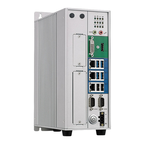
Two DB9 ports used to connect RS232/422/485 compatible devices. Power Button Press to power-on or power-off the system. 24V DC Input Used to plug a DC power cord. NIFE 300P2/P2E/E16 NIFE 300P3 Copyright © 2016 NEXCOM International Co., Ltd. All Rights Reserved. NIFE 300 Series User Manual... -
Page 19: Top View
Used to connect a remote to power on/off the system. CFast Slot Remote Used to insert a CFast card. On/Off NIFE 300 PCI/PCIe Expansions NIFE 300P2/P2E/E16 NIFE 300P3 Copyright © 2016 NEXCOM International Co., Ltd. All Rights Reserved. NIFE 300 Series User Manual... -
Page 20: Mechanical Dimensions
Chapter 1: Product Introduction Mechanical Dimensions NIFE 300 4.20 4.20 Copyright © 2016 NEXCOM International Co., Ltd. All Rights Reserved. NIFE 300 Series User Manual... -
Page 21: Nife 300P2/Nife 300P2E/Nife 300E16
Chapter 1: Product Introduction NIFE 300P2/NIFE 300P2E/NIFE 300E16 4.20 4.20 Copyright © 2016 NEXCOM International Co., Ltd. All Rights Reserved. NIFE 300 Series User Manual... -
Page 22: Nife 300P3
Chapter 1: Product Introduction NIFE 300P3 4.20 4.20 62.50 62.50 Copyright © 2016 NEXCOM International Co., Ltd. All Rights Reserved. NIFE 300 Series User Manual... -
Page 23: Chapter 2: Jumpers And Connectors
Static electricity can damage many of the electronic ▪ Use correct screws and do not over tighten screws. components. Humid environments tend to have less static electricity than Copyright © 2016 NEXCOM International Co., Ltd. All Rights Reserved. NIFE 300 Series User Manual... -
Page 24: Jumper Settings
(on) and open (off). Two-Pin Jumpers: Open (Left) and Short (Right) Three-Pin Jumpers: Pins 1 and 2 are Short Copyright © 2016 NEXCOM International Co., Ltd. All Rights Reserved. NIFE 300 Series User Manual... -
Page 25: Locations Of The Jumpers And Connectors For Nifb 300
Locations of the Jumpers and Connectors for NIFB 300 The figure below is the top view of the NIFB 300 main board which is the main board used in NIFE 300 series. It shows the locations of the jumpers and connectors. -
Page 26: Bottom View
Chapter 2: Jumpers and Connectors Bottom View PCIE1 MINI1 EDP1 CFAST1 Copyright © 2016 NEXCOM International Co., Ltd. All Rights Reserved. NIFE 300 Series User Manual... -
Page 27: Jumpers
Connector location: JP7 Settings Settings 1-2 On ATX Mode 1-2 On Normal 2-3 On AT Mode 2-3 On Clear CMOS 1-2 On: default 1-2 On: default Copyright © 2016 NEXCOM International Co., Ltd. All Rights Reserved. NIFE 300 Series User Manual... -
Page 28: Com3 Ri Select
Settings 1-2 On VCC5 1-2 On NORMAL 2-3 On VCC12 2-3 On CONFIGURE 4-5 On RING 4-5 On RECOVERY 4-5 On: default 1-2 On: default Copyright © 2016 NEXCOM International Co., Ltd. All Rights Reserved. NIFE 300 Series User Manual... -
Page 29: Pcie Configuration Settings
PCIe Configuration Settings Connector type: 1x3 3-pin header Connector location: JP9 Settings 1-2 On PCIe x16 2-3 On PCIe x8 + PCIe x8 1-2 On: default Copyright © 2016 NEXCOM International Co., Ltd. All Rights Reserved. NIFE 300 Series User Manual... -
Page 30: Connector Pin Definitions
PWR_PIN3 SP1_DCD SP1_DATA- SP1_TX- SP1_RXD SP1_DATA+ SP1_TX+ SP1_TXD SP1_RX+ SP1_DTR SP1_RX- SP1_DSR SP1_RTS- SP1_RTS SP1_RTS+ SP1_CTS SP1_CTS+ SP1_RI SP1_CTS- REAR_GND REAR_GND REAR_GND REAR_GND REAR_GND REAR_GND Copyright © 2016 NEXCOM International Co., Ltd. All Rights Reserved. NIFE 300 Series User Manual... -
Page 31: Com 2 Port (Rs232/422/485)
Definition SP2_DCD SP2_DATA- SP2_TX- SP2_RXD SP2_DATA+ SP2_TX+ SP2_TXD SP2_RX+ SP2_DTR SP2_RX- SP2_DSR SP2_RTS- SP2_RTS SP2_RTS+ SP2_CTS SP2_CTS+ SP2_RI SP2_CTS- REAR_GND REAR_GND REAR_GND REAR_GND REAR_GND REAR_GND Copyright © 2016 NEXCOM International Co., Ltd. All Rights Reserved. NIFE 300 Series User Manual... -
Page 32: Lan3 And Usb 2.0 Ports
10Mbps or no link LAN3 Definition Definition Definition Definition P5V_USB_P45 USB2N4_C LAN3_VCC LAN3_MDI0P USB2P4_C LAN3_MDI0N LAN3_MDI1P P5V_USB_P45 USB2N5_C LAN3_MDI1N LAN3_MDI2P USB2P5_C LAN3_MDI2N LAN3_MDI3P LAN3_MDI3N LAN3_LINK100#_LED LAN3_LINK LAN3_ACT#_LED LAN3_LED_P Copyright © 2016 NEXCOM International Co., Ltd. All Rights Reserved. NIFE 300 Series User Manual... -
Page 33: Lan2 And Usb 3.0 Ports
LAN2_VCC LAN2_MDI0P USB2P0_C LAN2_MDI0N LAN2_MDI1P USB3RN1_C USB3RP1_C LAN2_MDI1N LAN2_MDI2P USB3TN1_C LAN2_MDI2N LAN2_MDI3P USB3TP1_C P5V_USB_P01 LAN2_MDI3N USB2N1_C USB2P1_C LAN2_LINK100#_LED LAN2_LINK USB3RN2_C LAN2_ACT#_LED LAN2_ACTPW USB3RP2_C USB3TN2_C USB3TP2_C Copyright © 2016 NEXCOM International Co., Ltd. All Rights Reserved. NIFE 300 Series User Manual... -
Page 34: Lan1 And Usb 3.0 Ports
LAN1_VCC LAN1_MDI0P USB2P0_C LAN1_MDI0N LAN1_MDI1P USB3RN1_C USB3RP1_C LAN1_MDI1N LAN1_MDI2P USB3TN1_C LAN1_MDI2N LAN1_MDI3P USB3TP1_C P5V_USB_P01 LAN1_MDI3N USB2N1_C USB2P1_C LAN1_LINK100#_LED LAN1_LINK USB3RN2_C LAN1_ACT#_LED LAN1_ACTPW USB3RP2_C USB3TN2_C USB3TP2_C Copyright © 2016 NEXCOM International Co., Ltd. All Rights Reserved. NIFE 300 Series User Manual... -
Page 35: Dvi-D Connector
DVI1_CTRL_CLK_C HDMI_DATA1_N_C DVI1_CTRL_DAT_C HDMI_DATA0_P_C DVI1_DATA1_N_C DVI1_DATA1_P_C HDMI_DATA0_N_C HDMI_CLK_P_C HDMI_CLK_N_C DVI1_PWR_C DVI1_HPD HDMI_CLK HDMI_DAT DVI1_DATA0_N_C DVI1_DATA0_P_C HDMI_PWR_C HDMI_HPD_C Chassis_GND Chassis_GND DVI1_CLK_P_C DVI1_CLK_N_C Chassis_GND Chassis_GND Chassis_GND Chassis_GND Copyright © 2016 NEXCOM International Co., Ltd. All Rights Reserved. NIFE 300 Series User Manual... -
Page 36: Audio Connectors
PWR_LED_P PWR_LED_N Chassis_GND RX2_P COM2_RXLEDN LINE_OUT_LC AGND TX2_P COM2_TXLEDN LED3 LINEOUT_JD LINE_OUT_RC RX1_P COM1_RXLEDN TX1_P COM1_TXLEDN SIO_GP36_64_P SIO_GP36_64 SIO_GP37_65_P SIO_GP37_65 LED4 SIO_GP15_66_P SIO_GP15_66 SIO_GP16_67_P SIO_GP16_67 Copyright © 2016 NEXCOM International Co., Ltd. All Rights Reserved. NIFE 300 Series User Manual... -
Page 37: Internal Connectors
Definition Definition Definition Definition VCC12 PWR_LED_P PWR_LED_N FAN TAC FAN CTL SATALED#_P SATALED# VCC3 LAN1_LED_LINK# VCC3 LAN2_LED_LINK# VCC3 LAN3_LED_LINK# VCC3 LAN1_ACT#_LED VCC3 LAN2_ACT#_LED VCC3 LAN3_ACT#_LED Copyright © 2016 NEXCOM International Co., Ltd. All Rights Reserved. NIFE 300 Series User Manual... -
Page 38: Debug Port
Connector type: 1x3 3-pin header, 2.0mm pitch Connector location: DE1 Connector location: JP4 Definition Definition Definition RST_SIO_N SMB_CLK CLK_PCI_P80 LPC_FRAME# SMB_DAT LPC_AD3 LPC_AD2 LPC_AD1 LPC_AD0 VCC3 VCC3 Copyright © 2016 NEXCOM International Co., Ltd. All Rights Reserved. NIFE 300 Series User Manual... -
Page 39: Remote Power On/Off & S3 Connector
Connector type: 1x10 10-pin header Connector location: JP5 Connector location: COM3 and COM4 Definition Definition Definition PWRBTN#_J COM_DCD#3 COM_RXD3 COM_TXD3 COM_DTR#3 SLP_S3#_C COM_DSR#3 COM_RTS#3 COM_CTS#3 COM_RI#3_T Copyright © 2016 NEXCOM International Co., Ltd. All Rights Reserved. NIFE 300 Series User Manual... -
Page 40: Usb 2.0 Connector
Connector type: USB port Connector type: 1x4 4-pin header, 2.0mm pitch Connector location: USB1 Connector location: IN1 Definition Definition Definition Definition P5V_USB_P8 USB2N8_C LINE1-L1 AGND USB2P8_C LINEIN_JD LINE1-R1 Copyright © 2016 NEXCOM International Co., Ltd. All Rights Reserved. NIFE 300 Series User Manual... -
Page 41: Sata Power Connectors
Connector location: CN3 and CN4 Connector location: CN1 and CN2 Definition Definition Definition Definition VCC12 SATA_TXP0_C VCC5 SATA_TXN0_C SATA_RXN0_C SATA_RXP0_C Definition Definition SATA_TXP1_C SATA_TXN1_C SATA_RXN1_C SATA_RXP1_C Copyright © 2016 NEXCOM International Co., Ltd. All Rights Reserved. NIFE 300 Series User Manual... -
Page 42: Sim Card Slot
Connector type: 2x5 10-pin header, 2.0mm pitch Connector location: JP2 Definition Definition Definition Definition GPIO_PWR UIM_PWR UIM_RESET UIM_CLK GPIO80 GPIO84 GPIO81 GPIO85 UIM_VPP UIM_DATA GPIO82 GPIO86 GPIO83 GPIO87 Copyright © 2016 NEXCOM International Co., Ltd. All Rights Reserved. NIFE 300 Series User Manual... -
Page 43: Reset Connector
Power Connector Connector type: 1x2 2-pin header, 1.25mm pitch Connector type: 2x2 4-pin header Connector location: RESET1 Connector location: CON1 Definition Definition Definition PM_RESET#_J VIN_3 VIN_3 Copyright © 2016 NEXCOM International Co., Ltd. All Rights Reserved. NIFE 300 Series User Manual... -
Page 44: Power Button
Definition Definition Definition PWRBTN#_C EDP_DISP_UTIL EDP_HPD EDP_BKLTEN PB_POWER EDP_VDDEN EDP_BKLTCTL EDP_AUXN EDP_AUXP EDP_TXN3 EDP_TXP3 EDP_TXN2 EDP_TXP2 EDP_TXN1 EDP_TXP1 EDP_TXN0 EDP_TXP0 VCC12 VCC12 VCC12 VCC3 VCC3 Copyright © 2016 NEXCOM International Co., Ltd. All Rights Reserved. NIFE 300 Series User Manual... -
Page 45: Cfast
PC17 KDAT MDAT KCLK MCLK Definition Definition SATA_TP2_C SATA_TN2_C CFAST_LED1_C CFAST_LED2_C SATA_RN2_C PC10 SATA_RP2_C PC11 PC12 CFAST_CDI PC13 VCC3 PC14 VCC3 PC15 PC16 PC17 CFAST_CDO_C Copyright © 2016 NEXCOM International Co., Ltd. All Rights Reserved. NIFE 300 Series User Manual... -
Page 46: Mini-Pcie Connector (Wlan/Gsm)
PCH_WIFI_TXN4 SMB_DAT MINICARD1CLKREQ# UIM_PWR PCH_WIFI_TXP4 UIM_DATA USB2N6_C CLK_WIFI_N_C UIM_CLK USB2P6_C CLK_WIFI_P_C UIM_RESET 3VSB_MINI1 UIM_VPP 3VSB_MINI1 MINICARD1DIS# CL_CLK_C RST_MINIPCIE1 CL_DAT_C 1V5_MINI1 PCIE_RN3_WIFI_C 3VSB_MINI1 CL_RST#_C PCIE_RP3_WIFI_C 3VSB_MINI2 Copyright © 2016 NEXCOM International Co., Ltd. All Rights Reserved. NIFE 300 Series User Manual... -
Page 47: Mini-Pcie/Msata Connector
Definition WAKE_N 3VSB_MINI2 1V5_MINI2 SMB_CLK 1V5_MINI2 PCIE_mSATA_TXN_C SMB_DAT MINICARD2CLKREQ# PCIE_mSATA_TXP_C USB2N7_C CLK_MINI_N_C USB2P7_C CLK_MINI_P_C 3VSB_MINI2 3VSB_MINI2 MINICARD2DIS# RST_MINIPCIE2 1V5_MINI2 PCIE_mSATA_RXP_C _C 3VSB_MINI2 PCIE_mSATA_RXN_C PCIE_mSATA_SEL_51 3VSB_MINI2 Copyright © 2016 NEXCOM International Co., Ltd. All Rights Reserved. NIFE 300 Series User Manual... -
Page 48: Pcie X16 Slot
PEG_RXP2 PCIEX16_TMS VCC3 PEG_RXN2 VCC3 PCIEX16_TRST# PEG_TXP3_C VCC3 3VSB PEG_TXN3_C RST_PCIEX16 3VSB PEG_RXP3 PEG_RXN3 CLK_PEG_A_P CLK_PEG_A_N PEG_TXP0_C PEG_TXN0_C PEG_TXP4_C PEG_RXP0 PEG_TXN4_C PEG_RXN0 PRSNT2#_1_C PEG_RXP4 PEG_RXN4 Copyright © 2016 NEXCOM International Co., Ltd. All Rights Reserved. NIFE 300 Series User Manual... - Page 49 PEG_RXN12 PEG_RXP7 PEG_TXP13_C PEG_RXN7 PEG_TXN13_C PEG_RXP13 PEG_TXP8_C PEG_RXN13 PEG_TXN8_C PEG_TXP14_C PEG_RXP8 PEG_TXN14_C PEG_RXN8 PEG_RXP14 PEG_TXP9_C PEG_RXN14 PEG_TXN9_C PEG_TXP15_C PEG_RXP9 PEG_TXN15_C PEG_RXN9 PEG_RXP15 PEG_TXP10_C PEG_RXN15 PEG_TXN10_C Copyright © 2016 NEXCOM International Co., Ltd. All Rights Reserved. NIFE 300 Series User Manual...
-
Page 50: Chapter 3: System Setup
Installing a CPU 1. Remove the 4 flat screws on the top cover. 2. Lift up the cover and remove it from the chassis. Copyright © 2016 NEXCOM International Co., Ltd. All Rights Reserved. NIFE 300 Series User Manual... - Page 51 3. Remove the mounting screws that secure the heat sink to the chassis. 4. The CPU socket is readily accessible after you have removed the heat sink. Load Retention lever Copyright © 2016 NEXCOM International Co., Ltd. All Rights Reserved. NIFE 300 Series User Manual...
- Page 52 ▪ Handle the CPU by its edges and avoid touching the pins. ▪ The CPU will fit in only one orientation and can easily be CAUTION! CAUTION! CAUTION! inserted without exerting any force. Copyright © 2016 NEXCOM International Co., Ltd. All Rights Reserved. NIFE 300 Series User Manual...
- Page 53 Do not force the CPU into the socket. Forcing the CPU into CAUTION! CAUTION! CAUTION! the socket may bend the pins and damage the CPU. Copyright © 2016 NEXCOM International Co., Ltd. All Rights Reserved. NIFE 300 Series User Manual...
- Page 54 Chapter 3: System Setup 9. Tighten the screws to secure the heat sink in place. Copyright © 2016 NEXCOM International Co., Ltd. All Rights Reserved. NIFE 300 Series User Manual...
-
Page 55: Installing A So-Dimm Memory Module
Chapter 3: System Setup Installing a SO-DIMM Memory Module 1. Remove the chassis before installing a SO-DIMM module. 2. Locate the SO-DIMM memory sockets. Memory sockets Copyright © 2016 NEXCOM International Co., Ltd. All Rights Reserved. NIFE 300 Series User Manual... - Page 56 3. Insert the memory module into the socket. 4. Apply even pressure to both ends of the module until it is locked by the latches. Copyright © 2016 NEXCOM International Co., Ltd. All Rights Reserved. NIFE 300 Series User Manual...
- Page 57 6. Insert another SO-DIMM module into the socket and apply even pressure to both ends of the module until it is locked by the latches. Copyright © 2016 NEXCOM International Co., Ltd. All Rights Reserved. NIFE 300 Series User Manual...
-
Page 58: Installing A Sim Card
Chapter 3: System Setup Installing a SIM Card 1. Locate the mini-PCIe slot and remove the bracket first. 2. Locate the SIM card holder. SIM card holder Copyright © 2016 NEXCOM International Co., Ltd. All Rights Reserved. NIFE 300 Series User Manual... - Page 59 3. Release the SIM card cover and place the SIM card into the holder. 4. Close the cover and secure the SIM card into position. Copyright © 2016 NEXCOM International Co., Ltd. All Rights Reserved. NIFE 300 Series User Manual...
-
Page 60: Installing A Cfast Card
Chapter 3: System Setup Installing a CFast Card 1. Locate the CFast socket on the top cover. 2. Remove the cover of the CFast socket. CFast cover Copyright © 2016 NEXCOM International Co., Ltd. All Rights Reserved. NIFE 300 Series User Manual... - Page 61 Chapter 3: System Setup 3. Insert the CFast card into the socket. 4. Ensure the CFast card is installed and engaged firmly with a click sound. Copyright © 2016 NEXCOM International Co., Ltd. All Rights Reserved. NIFE 300 Series User Manual...
-
Page 62: Installing A 3G/Gsm Module
Chapter 3: System Setup Installing a 3G/GSM Module 1. Install the 3G/GSM module into the 3G/GSM slot. 2. Fix the antenna cable to the 3G/GSM module. Copyright © 2016 NEXCOM International Co., Ltd. All Rights Reserved. NIFE 300 Series User Manual... - Page 63 Chapter 3: System Setup 3. Locate the antenna hole on the front panel, and insert the antenna jack 4. Fix the antenna jack with rings. through the hole. Copyright © 2016 NEXCOM International Co., Ltd. All Rights Reserved. NIFE 300 Series User Manual...
- Page 64 Chapter 3: System Setup 5. Install the antenna. Copyright © 2016 NEXCOM International Co., Ltd. All Rights Reserved. NIFE 300 Series User Manual...
-
Page 65: Installing An Msata Module (Nife 300 Only)
The following instructions apply to NIFE 300 only. 1. Remove the mini-PCIe cover on the side panel. 2. Locate the mini-PCIe socket, then install and fix the mSATA module into the socket. Copyright © 2016 NEXCOM International Co., Ltd. All Rights Reserved. NIFE 300 Series User Manual... - Page 66 Chapter 3: System Setup 3. Ensure both screws are fixed tightly to the socket. Copyright © 2016 NEXCOM International Co., Ltd. All Rights Reserved. NIFE 300 Series User Manual...
-
Page 67: Installing An Msata Module (Nife 300P2/P3/P2E/E16/E3)
The following instructions apply to NIFE 300P2/P2E/E16/P3/E3. 1. Remove the side panel. 2. Locate the mini-PCIe socket, then install and fix the mSATA module into the socket. Copyright © 2016 NEXCOM International Co., Ltd. All Rights Reserved. NIFE 300 Series User Manual... - Page 68 Chapter 3: System Setup 3. Ensure both screws are fixed tightly to the socket. Copyright © 2016 NEXCOM International Co., Ltd. All Rights Reserved. NIFE 300 Series User Manual...
-
Page 69: Installing An External Sata Hard Drive
Installing an External SATA Hard Drive 1. Remove the external HDD cover. 2. Pull out the HDD bracket and place the HDD into the bracket. cover Copyright © 2016 NEXCOM International Co., Ltd. All Rights Reserved. NIFE 300 Series User Manual... - Page 70 3. Fix the HDD onto the HDD bracket from the bottom side using screws. 4. Install the HDD bracket into the external HDD drive bay, and secure the external HDD cover back to the drive bay. Copyright © 2016 NEXCOM International Co., Ltd. All Rights Reserved. NIFE 300 Series User Manual...
-
Page 71: Installing An Internal Sata Hard Drive
Chapter 3: System Setup Installing an Internal SATA Hard Drive 1. Remove the chassis cover. 2. Locate the internal HDD bracket. bracket Copyright © 2016 NEXCOM International Co., Ltd. All Rights Reserved. NIFE 300 Series User Manual... - Page 72 Chapter 3: System Setup 3. Install and fix the HDD to the internal HDD bracket. Copyright © 2016 NEXCOM International Co., Ltd. All Rights Reserved. NIFE 300 Series User Manual...
-
Page 73: Installing A Pci Or Pcie Card
The following instructions apply to NIFE 300P2/P2E/E16/P3/E3, and does not apply to NIFE 300. 1. Remove the side panel. 2. Locate and remove the screw on the PCI/PCIe bracket cover. Copyright © 2016 NEXCOM International Co., Ltd. All Rights Reserved. NIFE 300 Series User Manual... - Page 74 Chapter 3: System Setup 3. Remove the plastic screw holder if the height of the PCI/PCIe card is 4. Install the PCI/PCIe card into the slot. sufficient. Copyright © 2016 NEXCOM International Co., Ltd. All Rights Reserved. NIFE 300 Series User Manual...
-
Page 75: Pci Volts Configuration On Nife 300 Riser Cards
2x PCI Slots 2-3(5V), 1-1(3.3V) 1x PCI Slot and NIFE 300P2E 1x PCIe Slot 2-3(5V), 1-1(3.3V) 2x PCI Slots and NIFE 300P3 1x PCIe Slot 2-3(5V), 1-1(3.3V) Copyright © 2016 NEXCOM International Co., Ltd. All Rights Reserved. NIFE 300 Series User Manual... -
Page 76: Wallmount Mounting
Chapter 3: System Setup Wallmount Mounting The main mounting method of the NIFE 300 series is wallmount. Please locate the wallmount fixing holes at the rear of the NIFE 300 series for wallmount mounting. Copyright © 2016 NEXCOM International Co., Ltd. All Rights Reserved. -
Page 77: Chapter 4: Bios Setup
BIOS is updated in the future. second, to make settings appropriate for the way you use the computer. To check for the latest updates and revisions, visit the NEXCOM website at When to Configure the BIOS www.nexcom.com.tw. -
Page 78: Default Configuration
Setup. Load optimized default values. Press the key to enter Setup: Saves and exits the Setup program. Press <Enter> to enter the highlighted sub-menu Copyright © 2016 NEXCOM International Co., Ltd. All Rights Reserved. NIFE 300 Series User Manual... - Page 79 When “” appears on the left of a particular field, it indicates that a submenu which contains additional options are available for that field. To display the submenu, move the highlight to that field and press Copyright © 2016 NEXCOM International Co., Ltd. All Rights Reserved. NIFE 300 Series User Manual...
-
Page 80: Bios Setup Utility
24-hour military-time clock. For example, 1 p.m. is 13:00:00. Hour displays hours from 00 to 23. Minute displays minutes from 00 to 59. Second displays seconds from 00 to 59. Copyright © 2016 NEXCOM International Co., Ltd. All Rights Reserved. NIFE 300 Series User Manual... -
Page 81: Advanced
Displays the Super I/O chip used on the board. F1: General Help F2: Previous Values F3: Optimized Defaults F4: Save & Exit ESC: Exit Version 2.17.1254. Copyright (C) 2015 American Megatrends, Inc. Copyright © 2016 NEXCOM International Co., Ltd. All Rights Reserved. NIFE 300 Series User Manual... - Page 82 Select this to change the serial port mode to RS232, RS422, RS485 or RS485 Auto. Auto. Terminal Resistor Terminal Resistor Enables or disables the terminal resistor. Enables or disables the terminal resistor. Copyright © 2016 NEXCOM International Co., Ltd. All Rights Reserved. NIFE 300 Series User Manual...
- Page 83 Version 2.17.1254. Copyright (C) 2015 American Megatrends, Inc. Version 2.17.1254. Copyright (C) 2015 American Megatrends, Inc. Serial Port Serial Port Enables or disables the serial port. Enables or disables the serial port. Copyright © 2016 NEXCOM International Co., Ltd. All Rights Reserved. NIFE 300 Series User Manual...
- Page 84 Configures the speed of the fan, the options are Always Full Speed, Enable Smart Fan and Disable. System Temperature Detects and displays the current system temperature. CPU Temperature Detects and displays the current CPU temperature. Copyright © 2016 NEXCOM International Co., Ltd. All Rights Reserved. NIFE 300 Series User Manual...
- Page 85 Enables or disables CPU C States support. Intel ® Virtualization Technology Enables or disables Intel Virtualization technology. When enabled, a VMM can utilize the additional hardware capabilities provided by Vanderpool Technology. Copyright © 2016 NEXCOM International Co., Ltd. All Rights Reserved. NIFE 300 Series User Manual...
- Page 86 This option allows you to create RAID or Intel Matrix Storage Onboard LAN PXE configuration on Serial ATA devices. Enables or disables onboard LAN PXE ROM. Copyright © 2016 NEXCOM International Co., Ltd. All Rights Reserved. NIFE 300 Series User Manual...
- Page 87 This is a workaround for OSs that does not support XHCI hand-off. The XHCI ownership change should be claimed by the XHCI driver respectively. Device reset time-out Selects the USB mass storage device start unit command timeout. Copyright © 2016 NEXCOM International Co., Ltd. All Rights Reserved. NIFE 300 Series User Manual...
-
Page 88: Chipset
Setting incorrect field values may cause the system to Enters the graphics chip settings sub-menu. malfunction. PEG Port Configuration Enters the PEG port settings sub-menu. Memory Configuration Enters the memory settings sub-menu. Copyright © 2016 NEXCOM International Co., Ltd. All Rights Reserved. NIFE 300 Series User Manual... - Page 89 SG for switchable GFx. Primary PEG Select which PEG device should be the primary PEG. Primary PCIE Select which PCIE device should be the primary PCIE. Copyright © 2016 NEXCOM International Co., Ltd. All Rights Reserved. NIFE 300 Series User Manual...
- Page 90 Secondary IGFX Boot Display Select the secondary display device. LCD Panel Type Select the LCD panel used by the internal graphics device by selecting the appropriate setup item. Copyright © 2016 NEXCOM International Co., Ltd. All Rights Reserved. NIFE 300 Series User Manual...
- Page 91 Enables or disables the root port. Displays the information on the memory installed. Max Link Speed Select the maximum link speed of the PEG device. Copyright © 2016 NEXCOM International Co., Ltd. All Rights Reserved. NIFE 300 Series User Manual...
-
Page 92: Security
NumLock on wherein the function of the numeric keypad is the number keys. When set to Off, the function of the numeric keypad is the arrow keys. Copyright © 2016 NEXCOM International Co., Ltd. All Rights Reserved. NIFE 300 Series User Manual... -
Page 93: Save & Exit
To exit the Setup utility without saving the changes, select this field then press <Enter>. You may be prompted to confirm again before exiting. You can also press <ESC> to exit without saving the changes. Copyright © 2016 NEXCOM International Co., Ltd. All Rights Reserved. NIFE 300 Series User Manual... - Page 94 Restore User Defaults To restore the BIOS to user default settings, select this field then press <Enter>. A dialog box will appear. Confirm by selecing Yes. Copyright © 2016 NEXCOM International Co., Ltd. All Rights Reserved. NIFE 300 Series User Manual...
-
Page 95: Appendix A: Power Consumption
3. Measure the power consumption and record it. 4. Run Burn-in test program to apply 100% full loading. 5. Measure the power consumption and record it. Copyright © 2016 NEXCOM International Co., Ltd. All Rights Reserved. NIFE 300 Series User Manual... -
Page 96: Appendix B: Watchdog Programming Guide
;*Setup WDT time-out value. this demo code is used to program the time-out value with 4 sec. outportb(Superio_Port, 0x73); outportb(Superio_Port+1, 0x04); ;*Exit the MB PnP Mode outportb(Superio_Port, 0x02); outportb(Superio_Port+1, 0x02); Copyright © 2016 NEXCOM International Co., Ltd. All Rights Reserved. NIFE 300 Series User Manual... -
Page 97: Appendix C: Gpi/O Programming Guide
GPI/O (General Purpose Input/Output) pins are provided for custom system design. This appendix provides definitions and its default setting for the ten GPI/O pins in the NIFE 300 series. The pin definition is shown in the following table: PowerOn PowerOn... - Page 98 #define GPOA2_HI outportb(GPIO_PORT+2, 0x80) #define GPOA2_LO outportb(GPIO_PORT+2, 0x00) #define GPOA1_HI outportb(GPIO_PORT+2, 0x40) #define GPOA1_LO outportb(GPIO_PORT+2, 0x00) void main(void) GPO4_HI; GPO6_LO; GPO8_HI; GPO10_LO; GPOA4_HI; GPOA3_LO; GPOA2_HI; GPOA1_LO; Copyright © 2016 NEXCOM International Co., Ltd. All Rights Reserved. NIFE 300 Series User Manual...
-
Page 99: Riser Card 3.3V And 5V Jumper Configuration
7-8 On (Default) Short IRQ#A Status Function Description 1-2 On Short AD19 3-4 On Short AD18 5-6 On Short AD17 7-8 On (Default) Short AD16 Copyright © 2016 NEXCOM International Co., Ltd. All Rights Reserved. NIFE 300 Series User Manual... - Page 100 INT Select for CN2 Connector (JP2) Status Function Description 1-2 On Short IRQ#D 3-4 On Short IRQ#C 5-6 On Short IRQ#A 7-8 On (Default) Short IRQ#B Copyright © 2016 NEXCOM International Co., Ltd. All Rights Reserved. NIFE 300 Series User Manual...
Need help?
Do you have a question about the NIFE 300 Series and is the answer not in the manual?
Questions and answers