
Related Manuals for Nexcom Neu-X60


Summary of Contents for Nexcom Neu-X60
- Page 1 NEXCOM International Co., Ltd. Intelligent Platform & Services Business Unit Edge Computing System Neu-X60 User Manual NEXCOM International Co., Ltd. www.nexcom.com Published August 2024...
-
Page 2: Table Of Contents
Precautions ....................6 Acknowledgements ................iv Jumper Settings ..................7 Regulatory Compliance Statements ............iv Locations of the Jumpers and Connectors for the Neu-X60 Series ...8 Declaration of Conformity ..............iv Jumpers & DIP Switches ................9 RoHS Compliance ................... v Clear CMOS ..................9 Warranty and RMA ................ - Page 3 Main ....................41 Advanced ..................42 Security .....................48 Boot ....................49 Save & Exit ..................50 Appendix A: Power Consumption Appendix B: GPI/O Programming Guide F81804U GPI/O Programming Guide (PCB A) ........65 Copyright © 2024 NEXCOM International Co., Ltd. All Rights Reserved. Neu-X60 User Manual...
-
Page 4: Preface
No describes how to keep the system CE compliant. part of this manual may be reproduced, copied, translated or transmitted in any form or by any means without the prior written consent from NEXCOM Declaration of Conformity International Co., Ltd. -
Page 5: Rohs Compliance
(Cr6+) < 0.1% or 1,000ppm, Polybrominated biphenyls (PBB) < 0.1% or 1,000ppm, and Polybrominated diphenyl Ethers (PBDE) < 0.1% or 1,000ppm. In order to meet the RoHS compliant directives, NEXCOM has established an engineering and manufacturing task force to implement the introduction of green products. -
Page 6: Warranty And Rma
“NEXCOM RMA Service Form” for the RMA number apply process. ▪ If RMA goods can not be repaired, NEXCOM will return it to the customer without any charge. ▪ Customers can send back the faulty products with or without accessories (manuals, cable, etc.) and any components from the card, such as CPU... - Page 7 ESD workstation. If no such station is available, you can provide some ESD protection by wearing an antistatic wrist strap and attaching it to a metal part of the computer chassis. Copyright © 2024 NEXCOM International Co., Ltd. All Rights Reserved. Neu-X60 User Manual...
-
Page 8: Safety Information
There is a danger of explosion if battery is incorrectly replaced. Replace only with the same or equivalent type recommended by the manufacturer. Discard used batteries according to the manufacturer’s instructions. viii Copyright © 2024 NEXCOM International Co., Ltd. All Rights Reserved. Neu-X60 User Manual... -
Page 9: Safety Precautions
UL/IEC 60950-1 and/or UL/IEC 62368-1. If further assistance is needed, please contact NEXCOM International Co., Ltd. (UL file owner or brand owner) for further information. Copyright © 2024 NEXCOM International Co., Ltd. All Rights Reserved. -
Page 10: Technical Support And Assistance
Preface Technical Support and Assistance Conventions Used in this Manual 1. For the most updated information of NEXCOM products, visit NEXCOM’s Warning: website at www.nexcom.com. Information about certain situations, which if not observed, can cause personal injury. This will prevent injury to yourself 2. -
Page 11: Global Service Contact Information
16F, No.250, Sec.2, Chongde Rd., Tel: +886-2-8226-7786 Tel: +886-2-8976-3077 Beitun District, Fax: +886-2-8226-7782 Email: sales@diviotec.com Taichung City, 406, Taiwan, R.O.C. Email: services@tmrtek.com www.diviotec.com Tel: +886-4-2249-1179 www.tmrtek.com Fax: +886-4-2249-1172 Email: jacobhuang@nexaiot.com www.nexaiot.com Copyright © 2024 NEXCOM International Co., Ltd. All Rights Reserved. Neu-X60 User Manual... - Page 12 9F, Tamachi Hara Bldg., LongGang District, 4-11-5, Shiba Minato-ku, ShenZhen, 518112, China Tokyo, 108-0014, Japan Tel: +86-755-8364-7768 Tel: +81-3-5419-7830 Fax: +86-755-8364-7738 Fax: +81-3-5419-7832 Email: steveyang@nexcom.com.tw Email: sales@nexcom-jp.com www.nexcom.cn www.nexcom-jp.com Copyright © 2024 NEXCOM International Co., Ltd. All Rights Reserved. Neu-X60 User Manual...
-
Page 13: Package Contents
Preface Package Contents Before continuing, verify that the Neu-X60 package that you received is complete. Your package should have all the items listed in the following table. Item Part Number Neu-X60 System Power Adapter Item Part Number Name Description 7400050007X00 Power Adapter POWER ADAPTER W/LOCK EDAC:EA10681G(T09) 50W 12V/4.16A 113x49x35mm... -
Page 14: Ordering Information
Preface Ordering Information The following below provides ordering information for Neu-X60. Neu-X60 (P/N:10W100X6000X0) Intel N50 processor, Palm-sized Fanless Edge Computing System ® Copyright © 2024 NEXCOM International Co., Ltd. All Rights Reserved. Neu-X60 User Manual... -
Page 15: Chapter 1: Product Introduction
® ▪ 1x HDMI, 1x RS232/422/485, 2x USB3.2 Front Panel ▪ 1x miniPCIe full size for optional wireless module ▪ Great value for indoor applications Rear Panel Copyright © 2024 NEXCOM International Co., Ltd. All Rights Reserved. Neu-X60 User Manual... -
Page 16: Hardware Specifications
▪ 2 x 5-pin header for two USB 2.0 ports Expansion ▪ 1 x Full size miniPCIe slot with nano sim slot onboard, support optional WiFi / BT/ 4G module Copyright © 2024 NEXCOM International Co., Ltd. All Rights Reserved. Neu-X60 User Manual... -
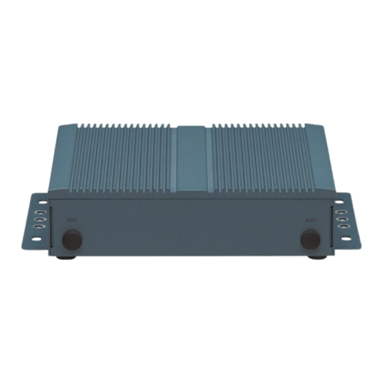
Page 17: Physical Features
Chapter 1: Product Introduction Physical Features Neu-X60 Front Panel Neu-X60 Rear Panel Grounding Hole 12V DC-In COM1 HDMI1 LAN1 USB3.2 Power Button Antenna Holes Copyright © 2024 NEXCOM International Co., Ltd. All Rights Reserved. Neu-X60 User Manual... -
Page 18: Mechanical Dimensions
Chapter 1: Product Introduction Mechanical Dimensions 156.00 143.00 130.00 Copyright © 2024 NEXCOM International Co., Ltd. All Rights Reserved. Neu-X60 User Manual... -
Page 19: Chapter 2: Jumpers And Connectors
Static electricity can damage many of the electronic ▪ Use correct screws and do not over tighten screws. components. Humid environments tend to have less static electricity than Copyright © 2024 NEXCOM International Co., Ltd. All Rights Reserved. Neu-X60 User Manual... -
Page 20: Jumper Settings
Refer to the illustrations below for examples of what the 2-pin and 3-pin jumpers look like when they are short (on) and open (off). Two-Pin Jumpers: Open (Left) and Short (Right) Three-Pin Jumpers: Pins 1 and 2 are Short Copyright © 2024 NEXCOM International Co., Ltd. All Rights Reserved. Neu-X60 User Manual... -
Page 21: Locations Of The Jumpers And Connectors For The Neu-X60 Series
Locations of the Jumpers and Connectors for the Neu-X60 Series The following figures show the motherboard of Neu-X60 and indicates the locations of jumpers and connectors. Refer to this chapter for detailed pin setting and definitions of connectors marked in pink on this figure. -
Page 22: Jumpers & Dip Switches
Connector type: 1x5-pin header, 2.0mm pitch Connector location: CLRCMOS Connector location: JP1 Settings Settings 1-2 On Normal (Default) Ring 2-3 On Clear CMOS COM1 Pin9 COM1_Pin9 +12V *1-2 On Default Copyright © 2024 NEXCOM International Co., Ltd. All Rights Reserved. Neu-X60 User Manual... -
Page 23: Connector Pin Definitions
DC-In Power Input Jack Connector type: Slim D-SUB connector, 9-pin Connector type: +12V Connector location: COM1 Connector location: DCIN1 Definition Definition Settings +12V N.C. N.C. CGND CGND Copyright © 2024 NEXCOM International Co., Ltd. All Rights Reserved. Neu-X60 User Manual... -
Page 24: Hdmi Port
Chapter 2: Jumpers and Connectors HDMI Port Connector type: HDMI Connector location: HDMI1 Definition Definition HDMI_TX2P HDMI_TX2N HDMI1_TX1P HDMI1_TX1N HDMI_TX0P HDMI_TX0N HDMI1_CLK_P HDMI1_CLK_N HDMI1_SCL HDMI1_SDA HDMI1_P5V HDMI1_HPD CGND CGND CGND CGND Copyright © 2024 NEXCOM International Co., Ltd. All Rights Reserved. Neu-X60 User Manual... -
Page 25: Lan1 Port (I226-V)
Steady Orange 100Mbps network link TCTG 10Mbps/No activity LAN1_MDI2P LAN1_MDI2N Act. (Right) Status LAN1_MDI3P LAN1_MDI3N Blinking Green Data activity LAN1_LED_ACT_POWER LAN1_LED_ACT# No activity LAN1_LED_LINK100# LAN1_LED_LINK2500# CGND CGND Copyright © 2024 NEXCOM International Co., Ltd. All Rights Reserved. Neu-X60 User Manual... -
Page 26: Power Switch Button
Settings Definition Definition SWITCH_NODE1 USB2_3N SWITCH_NODE2 USB2_3P SWITCH_NODE2 USB3_RX3N USB3_RX3P SWITCH_NODE1 USB3_TX3N LED- USB3_TX3P LED+ USB2_4N USB2_4P N.C. USB3_RX4N N.C. USB3_RX4P USB3_TX4N USB3_TX4P CGND CGND CGND CGND Copyright © 2024 NEXCOM International Co., Ltd. All Rights Reserved. Neu-X60 User Manual... -
Page 27: Internal I/O Interfaces
FAN Connector Connector type: 1x2-pin header, 1.25mm Connector type: 1x4-pin header, 2.54mm pitch Connector location: BAT Connector location: CPU_FAN Definition Definition +12V FAN SPEED DETECT FAN SPEED CONTROL Copyright © 2024 NEXCOM International Co., Ltd. All Rights Reserved. Neu-X60 User Manual... -
Page 28: 80 Debug Port Connector
Connector location: DEBUG Connector location: GPIO Definition Definition Definition Definition PLTRST# ESPI_CLK ESPI_CS# GPO0 GPO1 ESPI_IO3 ESPI_IO2 GPO2 GPO3 ESPI_IO1 ESPI_IO0 GPI0 GPI1 ESPI_RST# 3.3V GPI2 GPI3 Copyright © 2024 NEXCOM International Co., Ltd. All Rights Reserved. Neu-X60 User Manual... -
Page 29: M.2 Key M 2242 Connector
Connector location: M2M Definition Definition Definition Definition VCC3 PCIE2_RXP VCC3 PCIE3_RXN PCIE2_TXN PCIE3_RXP PCIE2_TXP M2M_LED# PCIE3_TXN VCC3 PCIE1_RXN PCIE3_TXP VCC3 PCIE1_RXP VCC3 PCIE2_RXN VCC3 PCIE1_TXN Continued on next page Copyright © 2024 NEXCOM International Co., Ltd. All Rights Reserved. Neu-X60 User Manual... - Page 30 Chapter 2: Jumpers and Connectors Definition Definition Definition Definition PCIE1_TXP DEVSLP CLK_PCIEP SATA_RXP(PCIE0_RXP) SATA_RXN(PCIE0_RXN) M2M_PEDET VCC3 SATA_TXN(PCIE0_TXN) VCC3 SATA_TXP(PCIE0_TXP) RESET# VCC3 CLKREQ# CLK_PCIEN WAKE# Copyright © 2024 NEXCOM International Co., Ltd. All Rights Reserved. Neu-X60 User Manual...
-
Page 31: Mini-Pcie Connector
3.3V CLKREQ# UIM_PWR PCIE5_RXP / SATA_RXN UIM_DATA 1.5V CLKN0 UIM_CLK SMB_CLK CLKP0 UIM_RESET PCIE5_TXN / SATA_TXN SMB_DATA UIM_VPP PCIE5_TXP / SATA_TXP USB2_6DN USB2_6DP Continued on next page Copyright © 2024 NEXCOM International Co., Ltd. All Rights Reserved. Neu-X60 User Manual... - Page 32 Chapter 2: Jumpers and Connectors Definition Definition 3.3V 3.3V 1.5V mSATA Presece Detection 3.3V Copyright © 2024 NEXCOM International Co., Ltd. All Rights Reserved. Neu-X60 User Manual...
-
Page 33: Internal I/O Interfaces
SIM Card Connector Connector type: Nano SIM Card connector System Reset Button Connector location: SIM Connector type: 1x2-pin header, 1.0mm pitch Connector location: RESET_BTN Definition Definition Definition RESET # Copyright © 2024 NEXCOM International Co., Ltd. All Rights Reserved. Neu-X60 User Manual... -
Page 34: Internal Usb2.0 Ports
Chapter 2: Jumpers and Connectors Internal USB2.0 Ports Connector type: 2x5-pin header, 2.0mm pitch Connector location: USB2_57P Definition Definition USB2_1N USB2_1P USB2_2P USB2_2N Copyright © 2024 NEXCOM International Co., Ltd. All Rights Reserved. Neu-X60 User Manual... -
Page 35: Chapter 3: System Setup
Loosen the screws on the left/right sides of the chassis. Loosen the screws on the bottom, and remove the cover from the chassis. Copyright © 2024 NEXCOM International Co., Ltd. All Rights Reserved. Neu-X60 User Manual... -
Page 36: Installing A So-Dimm Memory Module
Push the module down until the clips on both sides of the socket lock into position. SO-DIMM Socket Copyright © 2024 NEXCOM International Co., Ltd. All Rights Reserved. Neu-X60 User Manual... -
Page 37: Installing An M.2 M Key Ssd Module
Push the module down and secure it with a screw. M.2 M Key Slot Copyright © 2024 NEXCOM International Co., Ltd. All Rights Reserved. Neu-X60 User Manual... -
Page 38: Installing A Half Size Mini-Pcie Wi-Fi Module
45 degree angle until the gold-plated connector on the edge of the module completely disappears inside the slot. Push the module down and secure it with a screw. Copyright © 2024 NEXCOM International Co., Ltd. All Rights Reserved. Neu-X60 User Manual... -
Page 39: Installing A Mini-Pcie Lte Module
) to the LTE module and insert the antenna jacks end of the cables through the antenna holes. Refer to Assembling the Antennas section for more details. Copyright © 2024 NEXCOM International Co., Ltd. All Rights Reserved. Neu-X60 User Manual... -
Page 40: Assembling The Antennas
Insert the antenna jack end of the cables through the antenna holes. Ring 2 Ring 1 Connect the external antennas to the Wi-Fi antenna jacks. Copyright © 2024 NEXCOM International Co., Ltd. All Rights Reserved. Neu-X60 User Manual... -
Page 41: Wall Mounting Instructions
Secure the system to the wall by fastening screws through the mounting holes of the brackets, as indicated in the image below. The recommended screw type is #6-32, L defined by user (Q’ty: 4 pcs). Copyright © 2024 NEXCOM International Co., Ltd. All Rights Reserved. Neu-X60 User Manual... -
Page 42: Chapter 4: Bios Setup
This chapter describes how to use the BIOS setup program for the Neu-X60. The settings made in the setup program affect how the computer performs. The BIOS screens provided in this chapter are for reference only and may It is important, therefore, first to try to understand all the setup options, and change if the BIOS is updated in the future. -
Page 43: Default Configuration
Powering on the computer and immediately pressing <Del> allows you to enter Setup. Load optimized default values. Press the key to enter Setup: Saves and exits the Setup program. Press <Enter> to enter the highlighted sub-menu Copyright © 2024 NEXCOM International Co., Ltd. All Rights Reserved. Neu-X60 User Manual... - Page 44 When “” appears on the left of a particular field, it indicates that a submenu which contains additional options are available for that field. To display the submenu, move the highlight to that field and press Copyright © 2024 NEXCOM International Co., Ltd. All Rights Reserved. Neu-X60 User Manual...
-
Page 45: Bios Setup Utility
The Main menu is the first screen that you will see when you enter the BIOS hours from 00 to 23. Minute displays minutes from 00 to 59. Second Setup Utility. displays seconds from 00 to 59. Copyright © 2024 NEXCOM International Co., Ltd. All Rights Reserved. Neu-X60 User Manual... -
Page 46: Advanced
(G3 State). Wake on LAN/COM Setting incorrect field values may cause the system to malfunc- Enable or disable integrated LAN/COM port RI to wake the system. tion. Copyright © 2024 NEXCOM International Co., Ltd. All Rights Reserved. Neu-X60 User Manual... - Page 47 Auto means enabled. hardware capabilities provided by Vanderpool Technology. CPU SMM Enhancement PECI Enter the sub-menu of CPU SMM Enhancement. Enable or Disable PECI (Platform Environment Control Interface). Copyright © 2024 NEXCOM International Co., Ltd. All Rights Reserved. Neu-X60 User Manual...
- Page 48 SATA Test Mode Enable or disable test mode (loop back). ACPI Sleep State Select the highest ACPI sleep state the system will enter when the suspend button is pressed. Copyright © 2024 NEXCOM International Co., Ltd. All Rights Reserved. Neu-X60 User Manual...
- Page 49 Serial Port 1 Configuration PC Health Status Press <Enter> to set parameters of serial port 1 (COMA). Displays the temperatures of systems, CPU Fan speed, and voltages. Copyright © 2024 NEXCOM International Co., Ltd. All Rights Reserved. Neu-X60 User Manual...
- Page 50 Enable or disable IPv4 PXE support. If disabled, the IPv4 boot option will not be created. Ipv4 HTTP Support Enable or disable IPv4 HTTP support. If disabled, the IPv4 boot option will not be created. Copyright © 2024 NEXCOM International Co., Ltd. All Rights Reserved. Neu-X60 User Manual...
-
Page 51: Nvme Configuration
Media detect count Number of times presence of media will be checked. Use either +/- or numeric keys to set the value. Copyright © 2024 NEXCOM International Co., Ltd. All Rights Reserved. Neu-X60 User Manual... -
Page 52: Security
Chapter 4: BIOS Setup Security Administrator Password Select to reconfigure the administrator’s password. Copyright © 2024 NEXCOM International Co., Ltd. All Rights Reserved. Neu-X60 User Manual... -
Page 53: Boot
When set to Off, the function of the numeric keypad is the arrow keys. Quiet Boot Enable or disable quiet boot function. Copyright © 2024 NEXCOM International Co., Ltd. All Rights Reserved. Neu-X60 User Manual... -
Page 54: Save & Exit
To exit the Setup utility without saving the changes, select this field then press <Enter>. You may be prompted to confirm again before exiting. You can also press <ESC> to exit without saving the changes. Copyright © 2024 NEXCOM International Co., Ltd. All Rights Reserved. Neu-X60 User Manual... -
Page 55: Power Consumption Management
Full-Loading Mode Current ( A ) 1.61 A Total Watts(W) 19.32 W 開機瞬間的最大電流值 Current ( A ) 1.48 A 進入到 時的瞬間最大電流值 Current ( A ) 2.28 A Copyright © 2024 NEXCOM International Co., Ltd. All Rights Reserved. Neu-X60 User Manual... -
Page 56: Appendix B: Gpi/O Programming Guide
(PCB A) GPI/O (General Purpose Input/Output) pins are provided for custom system design. This appendix provides definitions and its default setting for the ten GPI/O pins in the Neu-X60 series. The pin definition is shown in the following table: Pin No. -
Page 57: Gpio Programming Sample Code
#define GPIO_PIN6 outportb(0x20B, ((inport(0x20B) & 0x7F) | 0x80) // Read GPIO_PIN8 #define GPIO_PIN8 inportb(0x20B) & 0x04 void main(void) UINT8 Value = 0; GPIO_PIN3; GPIO_PIN6; Value = GPIO_PIN8; Copyright © 2024 NEXCOM International Co., Ltd. All Rights Reserved. Neu-X60 User Manual... -
Page 58: Appendix C: Device I/O Programming Guide
Function GPI/O Type GPIO=Low (0) GPIO=High (1) USB power control GPIO04 Enable USB Power Disabl USB Power MINIPCIE power control GPIO00 Enable MINIPCIE Power Disable MINIPCIE Power Copyright © 2024 NEXCOM International Co., Ltd. All Rights Reserved. Neu-X60 User Manual... - Page 59 Bit0: for GP00, high is set to “1”, low is set to “0”. • Bit4: for GP04, high is set to “1”, low is set to “0”. Copyright © 2024 NEXCOM International Co., Ltd. All Rights Reserved. Neu-X60 User Manual...
-
Page 60: Appendix D: Watchdog Timer Setting
// Enter SuperIO Configuration outportb(WDT_VALUE, 0x03); // Set timer 3 second. outportb(WDT_SET, 0x31); // Enabled WDT // Use the second // Use the minute, change value to 0x39 Copyright © 2024 NEXCOM International Co., Ltd. All Rights Reserved. Neu-X60 User Manual...
Need help?
Do you have a question about the Neu-X60 and is the answer not in the manual?
Questions and answers