
Related Manuals for Nexcom NISE 90


Summary of Contents for Nexcom NISE 90
- Page 1 NEXCOM International Co., Ltd. Industrial Computing Solutions Fanless Computer NISE 90 User Manual NEXCOM International Co., Ltd. www.nexcom.com Published August 2013...
-
Page 2: Table Of Contents
Knowing Your NISE 90 ................3 USB 3/4 Connector ................16 Mechanical Dimensions ................5 PWR_BT/RET_BT/LED/SMBUS Pin Header ........17 NISE 90 ....................5 Mic-in Pin Header ................17 Line-in Pin Header ................18 Copyright © 2013 NEXCOM International Co., Ltd. All Rights Reserved. NISE 90 User Manual... - Page 3 Default Configuration ................32 Entering Setup ..................32 Legends ....................32 BIOS Setup Utility ..................34 Main ....................34 Advanced ..................35 Chipset ....................43 Boot ....................45 Security .....................47 Save & Exit ..................47 Copyright © 2013 NEXCOM International Co., Ltd. All Rights Reserved. NISE 90 User Manual...
-
Page 4: Preface
Acknowledgements The product(s) described in this manual complies with all applicable NISE 90 is a trademark of NEXCOM International Co., Ltd. All other product European Union (CE) directives if it has a CE marking. For computer systems names mentioned herein are registered trademarks of their respective to remain CE compliant, only CE-compliant parts may be used. -
Page 5: Rohs Compliance
(Cr6+) < 0.1% or 1,000ppm, Polybrominated biphenyls (PBB) < 0.1% or 1,000ppm, and Polybrominated diphenyl Ethers (PBDE) < 0.1% or 1,000ppm. In order to meet the RoHS compliant directives, NEXCOM has established an engineering and manufacturing task force to implement the introduction of green products. -
Page 6: Warranty And Rma
(manuals, cable, etc.) and any components from the card, such as CPU and RAM. If the components were suspected as part of the problems, ▪ If RMA goods can not be repaired, NEXCOM will return it to the customer please note clearly which components are included. Otherwise, NEXCOM without any charge. - Page 7 ESD workstation. If no such station is available, you can provide some ESD protection by wearing an antistatic wrist strap and attaching it to a metal part of the computer chassis. Copyright © 2013 NEXCOM International Co., Ltd. All Rights Reserved. NISE 90 User Manual...
-
Page 8: Safety Information
There is a danger of explosion if battery is incorrectly replaced. Replace only with the same or equivalent type recommended by the manufacturer. Discard used batteries according to the manufacturer’s instructions. viii Copyright © 2013 NEXCOM International Co., Ltd. All Rights Reserved. NISE 90 User Manual... -
Page 9: Safety Precautions
RECOMMENDED BY THE MANUFACTURER. DISCARD USED BATTERIES ACCORDING TO THE MANUFACTURER’S INSTRUCTIONS. 10. All cautions and warnings on the equipment should be noted. Copyright © 2013 NEXCOM International Co., Ltd. All Rights Reserved. NISE 90 User Manual... -
Page 10: Technical Support And Assistance
Preface Technical Support and Assistance Conventions Used in this Manual 1. For the most updated information of NEXCOM products, visit NEXCOM’s Warning: website at www.nexcom.com. Information about certain situations, which if not observed, can cause personal injury. This will prevent injury to yourself 2. -
Page 11: Global Service Contact Information
Chongde Rd., Beitun Dist., Shanghai, 200062, China Fax: +86-27-8722-7400 Taichung City 406, R.O.C. Tel: +86-21-6150-8008 Email: sales@nexcom.cn Tel: +886-4-2249-1179 Fax: +86-21-3251-6358 www.nexcom.cn Fax: +886-4-2249-1172 Email: sales@nexcom.cn www.nexcom.com.tw www.nexcom.cn Copyright © 2013 NEXCOM International Co., Ltd. All Rights Reserved. NISE 90 User Manual... - Page 12 Fax: +33 (0) 1 40 90 31 01 Email: sales.uk@nexcom.eu Email: sales.fr@nexcom.eu www.nexcom.eu www.nexcom.eu Germany NEXCOM GmbH Leopoldstraße Business Centre, Leopoldstraße 244, 80807 Munich, Germany Tel: +49-89-208039-278 Fax: +49-89-208039-279 Email: sales.de@nexcom.eu www.nexcom.eu Copyright © 2013 NEXCOM International Co., Ltd. All Rights Reserved. NISE 90 User Manual...
-
Page 13: Package Contents
Preface Package Contents Before continuing, verify that the NISE 90 package that you received is complete. Your package should have all the items listed in the following table. Item Part Number Name 4NCPM00302X00 Terminal Blocks 3P Phoenix Contact:1777992 50311F0110X00 Flat Head Screw Long FEI:F3x5ISO+NYLOK NIGP... -
Page 14: Ordering Information
Preface Ordering Information The following information below provides ordering information for NISE 90. • Barebone - NISE 90 (P/N: 10J00009000X0) Intel Atom E620 0.6GHz DIN Rail Fanless System with 512MB Memory onboard - NISE 91 (P/N: 10J00009100X0) Intel Atom E640 1.0GHz DIN Rail Fanless System with 1G Memory onboard Copyright ©... -
Page 15: Chapter 1: Product Introduction
▪ 3x USB2.0 / 1x VGA / 3x Serial Ports / 1x CAN bus ▪ 8CH GPI and 8CH GPO ▪ Support 1x 2.5” HDD drive bay ▪ Support 12V and 24VDC input Copyright © 2013 NEXCOM International Co., Ltd. All Rights Reserved. NISE 90 User Manual... -
Page 16: Hardware Specifications
- Sinusoidal: 0.3Grms @ 5~500 Hz according to IEC60068-2-6 - Clock frequency of 40MHz Certifications ▪ CE approval I/O Interface-Bottom ▪ FCC Class A ▪ 1x DB15 VGA port Copyright © 2013 NEXCOM International Co., Ltd. All Rights Reserved. NISE 90 User Manual... -
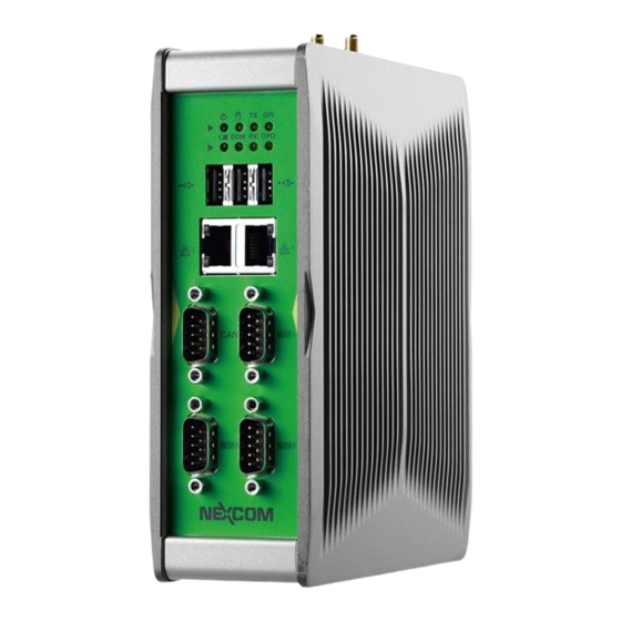
Page 17: Knowing Your Nise 90
COM port TX and RX signals, two programmable GPIO LEDs and a LED for battery power, replace battery when this LED is active. COM 3 COM 2 Copyright © 2013 NEXCOM International Co., Ltd. All Rights Reserved. NISE 90 User Manual... - Page 18 The GPO and GPI connectors support 8-channel GPO and 8-channel GPI. Used to connect an analog VGA monitor. Power Button Press to power-on or power-off the system. 12C/24V DC Input Power Button Copyright © 2013 NEXCOM International Co., Ltd. All Rights Reserved. NISE 90 User Manual...
-
Page 19: Mechanical Dimensions
Chapter 1: Product Introduction Mechanical Dimensions NISE 90 18.00 12.50 25.00 DIN RAIL CLIP 167.00 28.00 Copyright © 2013 NEXCOM International Co., Ltd. All Rights Reserved. NISE 90 User Manual... -
Page 20: Chapter 2: Jumpers And Connectors
Static electricity can damage many of the electronic ▪ Use correct screws and do not over tighten screws. components. Humid environments tend to have less static electricity than Copyright © 2013 NEXCOM International Co., Ltd. All Rights Reserved. NISE 90 User Manual... -
Page 21: Jumper Settings
(on) and open (off). Two-Pin Jumpers: Open (Left) and Short (Right) Three-Pin Jumpers: Pins 1 and 2 are Short Copyright © 2013 NEXCOM International Co., Ltd. All Rights Reserved. NISE 90 User Manual... -
Page 22: Locations Of The Jumpers And Connectors For Nisb 90
The figure below shows the location of the jumpers and connectors. NISB90 REV:C 4BJ00090C1X10 MADE IN TAIWAN JP12 IDE1 VGA2 R900 IDE1 JP10 JP13 COM3 LAN2 COM2 COM1 LAN1 USB0 USB1 USB2 Copyright © 2013 NEXCOM International Co., Ltd. All Rights Reserved. NISE 90 User Manual... -
Page 23: Jumpers
Connector location: JP5 Connector location: JP12 Settings Settings 1-2 On Normal 1-2 On 3.3V 2-3 On Clear BIOS 2-3 On 1-2 On: default 1-2 On: default Copyright © 2013 NEXCOM International Co., Ltd. All Rights Reserved. NISE 90 User Manual... -
Page 24: Connector Pin Definitions
Definition Definition LAN1_M0P LAN1_M3N LAN2_M0P LAN2_M3N LAN1_M0N LAN2_M0N LAN1_M1P LAN2_M1P LAN1_M1N LAN1_ACTP LAN2_M1N LAN2_ACTP LAN1_M2P LAN1_LED_ACT# LAN2_M2P LAN2_LED_ACT# LAN1_M2N LAN1_LINKP LAN2_M2N LAN2_LINKP LAN1_M3P LAN1LINKMIX LAN2_M3P LAN2LINKMIX Copyright © 2013 NEXCOM International Co., Ltd. All Rights Reserved. NISE 90 User Manual... -
Page 25: Usb0, Usb1 And Usb2 Ports
COM1 Connector Pin Definition Data 0+ Data 1+ RS232 RS485 RS422 Definition Definition Definition USB2 DCD1 DATA- RXD1 DATA+ Definition TXD1 DTR1 Data 2- Data 2+ DSR1 RTS1 CTS1 Copyright © 2013 NEXCOM International Co., Ltd. All Rights Reserved. NISE 90 User Manual... -
Page 26: Com3 And Com2 Connector
RTS3 Green TXD3 CTS3 Blue DTR3 DDC Data HSYNC VSYNC DDC Clock COM 2 Connector Pin Definition Definition Definition DCD2 DSR2 RXD2 RTS2 TXD2 CTS2 DTR2 Copyright © 2013 NEXCOM International Co., Ltd. All Rights Reserved. NISE 90 User Manual... -
Page 27: Gpi & Gpo Connector
Definition Definition SIO_GPO21 SIO_GPI61 SIO_GPO24 SIO_GPO22 SIO_GPI64 SIO_GPI62 SIO_GPO27 SIO_GPO25 SIO_GPI67 SIO_GPI65 VCC5 SIO_GPO28 VCC5 SIO_GPI68 SIO_GPO29 SIO_GPI69 SIO_GPO20 SIO_GPI60 SIO_GPO23 SIO_GPI63 SIO_GPO26 SIO_GPI66 VCC5 VCC5 Copyright © 2013 NEXCOM International Co., Ltd. All Rights Reserved. NISE 90 User Manual... -
Page 28: 9~36V Dc Power Input
Chapter 2: Jumpers and Connectors 9~36V DC Power Input Connector type: Phoenix Contact 1x3 3-pin terminal block Connector location: CN2 Definition +12VIN OR +24VIN CH_GND Copyright © 2013 NEXCOM International Co., Ltd. All Rights Reserved. NISE 90 User Manual... -
Page 29: Internal Connectors
Connector type: 1x7 JST, 7-pin header, 2.5mm pitch Connector location: J1 Connector location: J6 Definition Definition Definition Definition Sense +12V Control +12V +12V Panel Backlight Enable Panel Backlight Brightness Control Copyright © 2013 NEXCOM International Co., Ltd. All Rights Reserved. NISE 90 User Manual... -
Page 30: Lvds Connector
Definition Definition DDC_CLK DDC_DATA Data 3- VCC_LCD LVDS_TXP0 Data 3+ Data 4- LVDS_TXP3 LVDS_TXN0 Data 4+ LVDS_TXN3 VCC_LCD LVDS_TXP1 LVDS_CLKP LVDS_TXN1 LVDS_CLKN V_INV LVDS_TXP2 V_INV LVDS_TXN2 Copyright © 2013 NEXCOM International Co., Ltd. All Rights Reserved. NISE 90 User Manual... -
Page 31: Pwr_Bt/Ret_Bt/Led/Smbus Pin Header
Connector type: 1x4 4-pin header, 2.0mm pitch Connector location: JP1 Connector location: JP9 Definition Definition Definition PWR_LED_N PWR_LED_P MIC1_L SATA_LED# SATA_LED_P MIC_JD SMB_C SMB_D VCC3V3 MIC1_R VCC3V3 POWER BOTTOM RESET BOTTOM Copyright © 2013 NEXCOM International Co., Ltd. All Rights Reserved. NISE 90 User Manual... -
Page 32: Line-In Pin Header
Connector type: 1x4 4-pin header, 2.0mm pitch Connector type: 1x4 4-pin header, 2.0mm pitch Connector location: JP13 Connector location: JP10 Definition Definition FLIN_L FLOUT_L LIN_JD LOUT_JD FLIN_R FLOUT_R Copyright © 2013 NEXCOM International Co., Ltd. All Rights Reserved. NISE 90 User Manual... -
Page 33: Poe Power Connector
Connector type: Standard Serial ATAII 7P (1.27mm, SATA-M-180) Connector type: 2x2 4-pin header, 3.5mm pitch Connector location: CN1 Connector location: J5 Definition Definition Definition SATA_RXN1 SATA_TXP1 SATA_RXP1 VIN Power SATA_TXN1 VIN Power Copyright © 2013 NEXCOM International Co., Ltd. All Rights Reserved. NISE 90 User Manual... -
Page 34: Sata1 Connector
Connector type: Standard Serial ATAII 7P (1.27mm, SATA-M-180) Connector type: 1x4 4-pin header, 2.54mm pitch Connector location: J4 Connector location: CN5 Definition Definition Definition SATA_RXN0 +12V SATA_TXP0 SATA_RXP0 SATA_TXN0 VCC5 Copyright © 2013 NEXCOM International Co., Ltd. All Rights Reserved. NISE 90 User Manual... -
Page 35: Sata-Dom Power Connector
Connector type: 1x2 2-pin header, 2.5mm pitch Connector type: 2x4 8-pin header, 2.54mm pitch Connector location: J8 Connector location: J2 Definition Definition Definition VCC5 KBMSVCC LKBCLK KBMSVCC LMCLK LKBDAT LMDAT Copyright © 2013 NEXCOM International Co., Ltd. All Rights Reserved. NISE 90 User Manual... -
Page 36: Com4 Box Pin Header
Connector type: 1x10 10-pin header, 1.0mm pitch Connector location: IDE1 Connector location: J16 Definition Definition Definition Definition SIO_DCD#4 SIO_RXD4 UIM_PWR UIM_RESET SIO_TXD4 SIO_DTR#4 UIM_CLK SIO_DSR#4 UIM_VPP UIM_DATA SIO_RTS#4 SIO_CTS#4 SIO_RI#4 Copyright © 2013 NEXCOM International Co., Ltd. All Rights Reserved. NISE 90 User Manual... -
Page 37: Mini-Pcie Connector
COEX1 UIM_VPP SMBCLK COEX2 PCIETX- +1.5V SMBDATA CLKREQ# Disable# PCIETX+ UIM_PWR PERST# +1.5V UIM_DATA PCIERX- USB_D- REF CLK- +3VSB UIM_CLK PCIERX+ USB_D+ REF CLK+ +3VSB +3VSB Copyright © 2013 NEXCOM International Co., Ltd. All Rights Reserved. NISE 90 User Manual... -
Page 38: Chapter 3: System Setup
1. Remove the mounting screw on the left side of the system and put them in 2. Lift up the cover and remove it from the chassis. a safe place for later use. Remove screws around this side of system Copyright © 2013 NEXCOM International Co., Ltd. All Rights Reserved. NISE 90 User Manual... -
Page 39: Installing A Sata Hard Drive
2. Connect the SATA data/power cable to the connector on the hard drive. bracket with the mounting holes aligned. Then use the provided screws to secure the drive in place SATA data/power cable Copyright © 2013 NEXCOM International Co., Ltd. All Rights Reserved. NISE 90 User Manual... - Page 40 Chapter 3: System Setup 3. Connect the other side of SATA data/power cable to the PCBA. 4. Secure the cover to its original position. SATA power cable SATA cable Copyright © 2013 NEXCOM International Co., Ltd. All Rights Reserved. NISE 90 User Manual...
-
Page 41: Installing A Wireless Lan Module (Half-Size)
1. Locate the Mini PCI Express slot on the board. 2. Fasten the wireless LAN module to the mini PCI express bracket. Mini PCI Express Slot Copyright © 2013 NEXCOM International Co., Ltd. All Rights Reserved. NISE 90 User Manual... - Page 42 4. Push the module down and then secure it with mounting screws. Screw Copyright © 2013 NEXCOM International Co., Ltd. All Rights Reserved. NISE 90 User Manual...
-
Page 43: Installing A Sim Card
1. Locate the SIM card socket on the PCBA, then lift up the socket cover. 2. Slide the SIM card into the slot with the golden contacts facing inwards. SIM card bracket SIM card Copyright © 2013 NEXCOM International Co., Ltd. All Rights Reserved. NISE 90 User Manual... - Page 44 Chapter 3: System Setup 3. Push the socket cover back to its original position. Copyright © 2013 NEXCOM International Co., Ltd. All Rights Reserved. NISE 90 User Manual...
-
Page 45: Chapter 4: Bios Setup
Chapter 4: BIOS Setup Chapter 4: BIOS Setup This chapter describes how to use the BIOS setup program for the NISE 90. The The settings made in the setup program affect how the computer performs. BIOS screens provided in this chapter are for reference only and may change if It is important, therefore, first to try to understand all the setup options, and the BIOS is updated in the future. -
Page 46: Default Configuration
Powering on the computer and immediately pressing <Del> allows you to enter Setup. Load optimized default values. Press the key to enter Setup: Saves and exits the Setup program. Press <Enter> to enter the highlighted sub¬menu Copyright © 2013 NEXCOM International Co., Ltd. All Rights Reserved. NISE 90 User Manual... - Page 47 When “” appears on the left of a particular field, it indicates that a submenu which contains additional options are available for that field. To display the submenu, move the highlight to that field and press Copyright © 2013 NEXCOM International Co., Ltd. All Rights Reserved. NISE 90 User Manual...
-
Page 48: Bios Setup Utility
00 to 59. Version 2.10.1208. Copyright (C) 2010 American Megatrends, Inc. Access Level Displays the access level of the current user in the BIOS. Copyright © 2013 NEXCOM International Co., Ltd. All Rights Reserved. NISE 90 User Manual... -
Page 49: Advanced
ESC: Exit Version 2.10.1208. Copyright (C) 2010 American Megatrends, Inc. Launch PXE OpROM Enables or disables the boot option for legacy network devices connected to LAN1. Copyright © 2013 NEXCOM International Co., Ltd. All Rights Reserved. NISE 90 User Manual... - Page 50 Version 2.10.1208. Copyright (C) 2010 American Megatrends, Inc. This field is used to enable or disable Intel ® SpeedStep™ This field is used to enable or disable hyper-threading. Copyright © 2013 NEXCOM International Co., Ltd. All Rights Reserved. NISE 90 User Manual...
- Page 51 Enables or disables Enhanced C1 state. Enhanced C2 Enables or disables Enhanced C2 state. Enhanced C3 Enables or disables Enhanced C3 state. Enhanced C4 Enables or disables Enhanced C4 state. Copyright © 2013 NEXCOM International Co., Ltd. All Rights Reserved. NISE 90 User Manual...
- Page 52 This is a workaround for OSes that does not support EHCI hand-off. The EHCI ownership change should be claimed by the EHCI driver. Device Reset Timeout USB mass storage device start unit command timeout. Copyright © 2013 NEXCOM International Co., Ltd. All Rights Reserved. NISE 90 User Manual...
- Page 53 Version 2.10.1208. Copyright (C) 2010 American Megatrends, Inc. Super IO Chip Serial Port Displays the Super I/O chip used on the board. This field is used to enable or disable the serial port. Copyright © 2013 NEXCOM International Co., Ltd. All Rights Reserved. NISE 90 User Manual...
- Page 54 Selects an optimal setting for the Super IO device. This field is used to configure the mode of serial port 0 as RS232, RS422, RS485 or RS485 AUTO. Copyright © 2013 NEXCOM International Co., Ltd. All Rights Reserved. NISE 90 User Manual...
- Page 55 Version 2.10.1208. Copyright (C) 2010 American Megatrends, Inc. This field configures the maximum baud rate of serial port 0, the options are 115200 bps and 921600 bps. Copyright © 2013 NEXCOM International Co., Ltd. All Rights Reserved. NISE 90 User Manual...
- Page 56 Detects and displays the current CPU temperature. System Temperature Detects and displays the current system temperature. CPU FAN Speed Detects and displays the CPU fan speed. Copyright © 2013 NEXCOM International Co., Ltd. All Rights Reserved. NISE 90 User Manual...
-
Page 57: Chipset
Version 2.10.1208. Copyright (C) 2010 American Megatrends, Inc. Version 2.10.1208. Copyright (C) 2010 American Megatrends, Inc. Select the amount of system memory used by the integrated graphics device. Copyright © 2013 NEXCOM International Co., Ltd. All Rights Reserved. NISE 90 User Manual... - Page 58 Enables or disables the SMBus controller. LAN1 and LAN2 Enables or disables LAN1 or LAN2. High Precision Timer Enables or disables the high precision event timer. Copyright © 2013 NEXCOM International Co., Ltd. All Rights Reserved. NISE 90 User Manual...
-
Page 59: Boot
Displays normal POST messages. Fast Boot Disabled Displays normal POST messages. Setup Prompt Timeout This section configures the number of seconds to wait for the setup activation key. Copyright © 2013 NEXCOM International Co., Ltd. All Rights Reserved. NISE 90 User Manual... - Page 60 F2: Previous Values F3: Optimized Defaults F4: Save & Exit ESC: Exit Version 2.10.1208. Copyright (C) 2011 American Megatrends, Inc. Sets the first legacy device to boot from. Copyright © 2013 NEXCOM International Co., Ltd. All Rights Reserved. NISE 90 User Manual...
-
Page 61: Security
To exit the Setup utility without saving the changes, select this field then press <Enter>. You may be prompted to confirm again before exiting. You can also press <ESC> to exit without saving the changes. Copyright © 2013 NEXCOM International Co., Ltd. All Rights Reserved. NISE 90 User Manual... - Page 62 Restore User Defaults To restore the BIOS to user default settings, select this field then press <Enter>. A dialog box will appear. Confirm by selecting Yes. Copyright © 2013 NEXCOM International Co., Ltd. All Rights Reserved. NISE 90 User Manual...
-
Page 63: Appendix A: Power Consumption
HITACHI 250GB 7200rpm 8Mb HTS723225L9A360 SATA-II CD-ROM CFast Power Supply POWER ADAPTER SPI:G.P FSP120-AAB(N091) Add-on Card CPU Cooler NISE90 HEATSINK System FAN Keyboard LEMEL B-5201-P Mouse GENIVS EASY MOUSE USB Copyright © 2013 NEXCOM International Co., Ltd. All Rights Reserved. NISE 90 User Manual... - Page 64 3. Measure the power consumption and record it. 4. Run Burn-in test program to apply 100% full loading 5. Measure the power consumption and record it. Copyright © 2013 NEXCOM International Co., Ltd. All Rights Reserved. NISE 90 User Manual...
-
Page 65: Appendix B: Gpi/O Programming Guide
IO base address : A00h This appendix provides definitions and its default setting for the Digital I/O pins in the NISE 90. The pin definition is shown in the following table: GPO20 Read/Write GPIO data by I/O port A04h(Bit0) GPO21 Read/Write GPIO data by I/O port A04h(Bit1) -
Page 66: Appendix C: Watchdog Timer
Users can select second or minute. Step3. See “TimeCountWDT” procedure #Set Watchdog Timer Time-out Value. Users can set time-out value. Step4: See ExitSetup procedure #Exit Setup Environment Copyright © 2013 NEXCOM International Co., Ltd. All Rights Reserved. NISE 90 User Manual... - Page 67 ENDP =============================================== TimeBaseWDT PROC al, 72h 2eh, al al, 10h ;Set WDT reset upon PWROK al, 80h ;Here!! set 80h for second, set 00h for minute Copyright © 2013 NEXCOM International Co., Ltd. All Rights Reserved. NISE 90 User Manual...
Need help?
Do you have a question about the NISE 90 and is the answer not in the manual?
Questions and answers