Table of Contents
Advertisement
Ultra
®
TT Automation Series
A NORDSON COMPANY
For EFD sales and service in over 30 countries,
contact EFD or go to www.efd-inc.com/contact
USA & Canada: 800-556-3484 or +1-401-434-1680
Europe: 0800 585733 or +44 (0) 1582 666334
Asia: +86 (21) 5854 2345
automation@efd-inc.com
©2007 Nordson Corporation 031907 v1.2
www.efd-inc.com/xyz
This is an EFD
®
publication, which is protected by copyright. No part of this document may be photocopied,
reproduced, or translated to another language without the prior written consent of EFD. The information
contained in this publication is subject to change without notice.
The Wave Design is a trademark of Nordson Corporation. Palm, Palm OS, Zire and Tungsten are trademarks of
Palm, Inc. Clie is a trademark of Sony Corporation. Bluetooth is a trademark of Bluetooth SIG, Inc. Socket is a
trademark of Socket Communications, Inc.
User's Guide
™
Advertisement
Table of Contents
Troubleshooting

Related Manuals for EFD Ultra 325TT


Summary of Contents for EFD Ultra 325TT
- Page 1 No part of this document may be photocopied, Europe: 0800 585733 or +44 (0) 1582 666334 reproduced, or translated to another language without the prior written consent of EFD. The information Asia: +86 (21) 5854 2345 contained in this publication is subject to change without notice.
- Page 2 We pledge that you will be completely satisfied with our products. We endeavor to ensure that every EFD product is produced to our no-compromise quality standards. If you feel that you are not receiving all the support you require, or if you have any questions or comments, I invite you to write or call me personally.
-
Page 3: Table Of Contents
........Specifications Figure 1: Dimensions of Ultra 325TT 9-11 . - Page 4 Ultra TT User's Guide ® Version 1.2 A NORDSON COMPANY Teaching a Continuous Path ........5.4.1 CP Line 39-40...
-
Page 5: Warnings
Ultra TT User's Guide ® Version 1.2 A NORDSON COMPANY SAFETY • Read and understand this User’s Guide and all safety labels before operating this machine. • Only a trained person is to be permitted to operate this machine. Training should include instructions in operation under normal conditions and emergency situations. - Page 6 (turning off the main circuit breaker) and during EMO (Emergency Machine Off) conditions. The Ultra TT maintains a vacuum in order to hold a column of fluid inside EFD barrel syringes. This is designed as a safeguard to prevent low viscosity fluid from being discharged at power-down or during EMO conditions.
-
Page 7: Log-Out Tag-Out Procedures
Ultra TT User's Guide ® Version 1.2 A NORDSON COMPANY WARNING! There are several pinch points (indicated with yellow hazard stickers) on this machine that should be avoided. Failure to do so while the machine is operating may cause serious injury. Potential Pinch Hazard LOCK-OUT TAG-OUT PROCEDURE Announce lockout to other personnel. -
Page 8: Operator Hazard Training
Ultra TT User's Guide ® Version 1.2 A NORDSON COMPANY 11. Block, chain or release stored energy sources. 12. Always unplug the machine and disconnect the main airline to the system before opening any panels for service. Once the machine has been disconnected from power and air, the electric cord and airline must remain in sight of the individual performing maintenance. -
Page 9: Specifications
Ultra TT User's Guide ® Version 1.2 A NORDSON COMPANY SPECIFICATIONS Ultra 325TT Ultra 525TT Work Area 325 x 325 x 100 525 x 525 x 100 Resolution (μm) Repeatability (μm) Max Speed (mm/sec) Acceleration 0.25g 0.25g Mechanical Configuration H-Bridge... - Page 10 Ultra TT User's Guide ® Version 1.2 A NORDSON COMPANY...
- Page 11 Ultra TT User's Guide ® Version 1.2 A NORDSON COMPANY...
-
Page 12: Shipping Contents
Palm handheld to Palm Corporation. Within the period of the warranty, EFD will repair or replace any defective component, or the entire system at EFD’s option, on authorized return of the part or complete system prepaid to the factory. -
Page 13: Getting Started
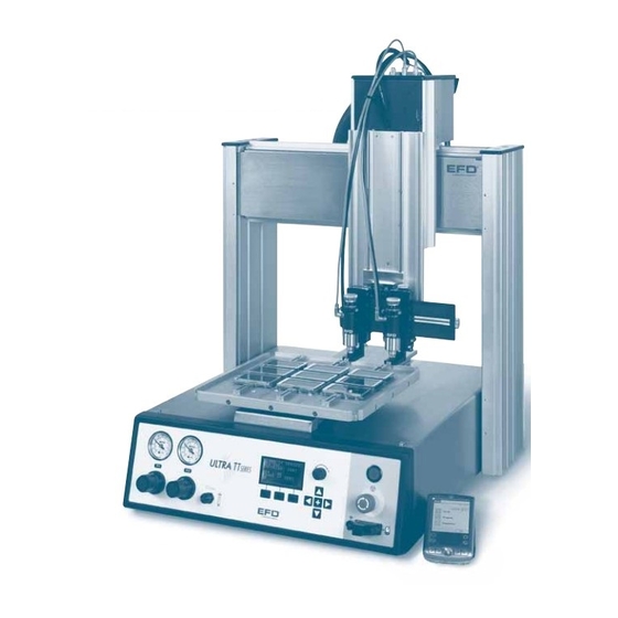
Ultra TT User's Guide ® Version 1.2 A NORDSON COMPANY GETTING STARTED SYSTEM FEATURES Z-head Electrical / Air Connections Mounting Bracket T-Slots Dispense Valves Universal Fixture Pressure Gauges Pressure Regulators Power Button EMO Button Vacuum Control Palm handheld Interactive LCD... -
Page 14: Front Panel
Ultra TT User's Guide ® Version 1.2 A NORDSON COMPANY 1.1.1 FRONT PANEL LCD Menu X/Y, Z/T Scroll Knob Jog Keys Interactive Power Button Vacuum control Emergency Machine Off (EMO) P2 Gauge P1 Gauge Interactive LCD RS232 & & Soft Keys PDA Connector Regulator Regulator... -
Page 15: Back Panel
Ultra TT User's Guide ® Version 1.2 A NORDSON COMPANY 1.1.2 BACK PANEL Socket ™ Main Power Adapter Circuit attached to Safety RS232 Discrete I/O Exhaust Fan Breaker Interlock General General Ethernet Main Air Purpose Main Power Purpose Entry Inputs Input Outputs RS232: The RS232 port can be used to connect the Ultra TT System to a Computer or PDA. -
Page 16: Machine Movements
• Once the dispensing procedure is complete, the dispensing head will move back to its preprogrammed park location. • When the tooling plate returns to the park location, the completed part can now be removed from the tooling plate. • The process is then repeated. Purchased from EFD or User to supply their own. -
Page 17: Setup
Ultra TT User's Guide ® Version 1.2 A NORDSON COMPANY Setup Preparing the Work Area Place the Ultra TT system on a stable table or bench. The Ultra TT needs enough space behind the machine (at least 250mm) to allow for the tooling to move to its home position. This space also ensures the fan duct on the back of the machine is not obstructed and thereby allows for air- cooling of the internal electronics. -
Page 18: Mounting Work-Holding Fixture
EFD offers two versions of fixture plates that can be used with the Ultra TT system. When dispensing onto low profile parts, it may be necessary to raise the fixture plate up so that the part(s) is within reach of the dispense valve. - Page 19 Ultra TT User's Guide ® Version 1.2 A NORDSON COMPANY The terminal blocks located on top of the Z- Terminal Block Pin No Function Head provide the connections needed to drive 4 Pos 790 Valve (+) Auger valves, height sensors, laser pointers and 4 Pos 790 Valve ( - ) auxiliary sensors.
-
Page 20: Mounting Valve Or Syringe Barrel
The Ultra TT system is a self-contained fluid-dispensing positioning system. It features integrated dispensing functions to operate any EFD valve or syringe barrel. The valve/syringe barrel attaches to the Z-carriage with the appropriate mounting fixture, and all pneumatic lines plug into the EFD quick-connect on the top of the Z-head. -
Page 21: Syringe Barrel
A NORDSON COMPANY 2.5.1 SYRINGE BARREL This section also applies to EFD dispensing valves 5800MP, HP4X, and HP7X, in addition to EFD’s range of syringe barrels. First, install the appropriate bracket e.g. universal syringe barrel bracket (P/N 700814) for syringe barrel installations, onto the Z-carriage. Insert the holding pins into the holes on the back plate to fit the size syringe barrel you are using. -
Page 22: Single Air Input Valve
Install the corresponding valve mounting fixture to the selected valve and then install the mounting fixture onto the Z-carriage. Refer to Section 8 (Ultra TT Accessories) for the entire list of EFD valve mounting fixtures. Attach the pulsed-air line to the P1 connector on top of the Z-head. -
Page 23: Multi Air Input Valve
Install the corresponding valve mounting fixture to the selected valve and then install the mounting fixture onto the Z-carriage. Refer to Section 8 (Accessories) for the entire list of EFD valve mounting fixtures. The pulsed air for valve operation plugs into the P1 connector on the Z-head. -
Page 24: Electric Auger Valve
Ultra TT User's Guide ® Version 1.2 A NORDSON COMPANY 2.5.4 ELECTRIC AUGER VALVE Install the Auger valve onto its corresponding valve bracket (P/N 700806) before attaching onto the T-slots of the Z-carriage. The Auger valve uses a brushed DC motor and requires two electrical connections into the 4-position terminal block located on top of the Z-Head. -
Page 25: Mounting Laser Pointer
Note that the laser pointer should be used in conjunction with the height sensor. The height sensor, along with the dot/line parameter setting of the “dispense gap” will determine the z-height at the dispense point. EFD provides a laser pointer and bracket (#700820) that can be easily mounted onto the Ultra TT. -
Page 26: Pda
NOT selected, then tap “OK”. Your PDA is now paired with the Ultra TT unit. The minimum Palm OS version is 4.0. The following Palm handhelds have been tested and are known to work with the EFD Ultra TT software and hardware: With the Teach Pendant Cable (700818): Zire ™... - Page 27 The next time you want to connect to the Ultra TT using the same PDA, launch the EFD Ultra TT PDA application. When asked if you wish to reconnect to the last device you communicated with, select “Yes”...
-
Page 28: System Configuration
Ultra TT User's Guide ® Version 1.2 A NORDSON COMPANY SYSTEM CONFIGURATION After performing the discovery and pairing of the PDA and the Ultra TT (Section 3), go into the Setup screens to configure your Ultra TT system for the specific valve/syringe barrel setup appropriate for your fluid dispensing application. -
Page 29: Valve #1
Ultra TT User's Guide ® Version 1.2 A NORDSON COMPANY 4.1.1 Valve #1 Next, select the model of Valve #1 from the drop-down menu. This software allows for specific settings to be configured for each valve in the Valve Options screen. Make the appropriate selections for the application requirements. -
Page 30: Teaching Tip To Probe Offset
Ultra TT User's Guide ® Version 1.2 A NORDSON COMPANY 4.1.1.1 Teaching Tip to Probe Offset This is an optional function. You will need to teach the dispense tip to probe offset only if you intend to use height sensor commands within the program. It is recommended you use the height sensor if your application requires very small dots or fine lines. -
Page 31: Toggle Valve
Ultra TT User's Guide ® Version 1.2 A NORDSON COMPANY 4.1.2 Toggle Valve If a Toggle bracket is selected, you will also need to teach an offset for the toggle valve. Follow the instructions in Section 4.1.1.1 to teach offset for the Toggle Valve. -
Page 32: Units
Note that the default toggle delay value is 0.5 seconds. The delay is used for both lowering the valve and for raising the valve. If you need to change this delay, please contact your EFD Ultra TT Representative. UNITS Select the desired units to be displayed from the drop-down menu. -
Page 33: Height Sensor
Ultra TT User's Guide ® Version 1.2 A NORDSON COMPANY HEIGHT SENSOR Each Ultra TT system is equipped with a standard tactile height sensor. The height sensor allows the Operator to activate the dispense gap function in a dot/line parameter. There are six (6) adjustable parameters for the height sensor: Probe Down Delay: This is the delay, after the tactile probe is extended (with a height sense command in a program), and before... -
Page 34: Park Location
Ultra TT User's Guide ® Version 1.2 A NORDSON COMPANY PARK LOCATION The park location is the position you want the dispense tip to move to after it has completed its taught program. This location is often a position closer to the work-piece than mechanical home in order to shorten the work cycle and also allows ample space for the part to be removed from the fixture plate. -
Page 35: Purge Toggle
Ultra TT User's Guide ® Version 1.2 A NORDSON COMPANY PURGE TOGGLE This screen performs the same function as in Section 4.5, except it is for the Toggle Valve instead of Valve #1. This purge routine can be accessed through the front panel LCD in program 98. -
Page 36: Programming
7. Tap “OK”. Tap “Teach” and then “OK”. This will open the program edit window. EFD can supply two tooling plates: 300 X 300mm (P/N 7007-300) or 500 X 500mm (P/N 7007-500). Alternative, user can design their own (reference System Drawings on Operation CD). -
Page 37: Teaching Dispensing Points
Ultra TT User's Guide ® Version 1.2 A NORDSON COMPANY 8. The Program window is where points are inserted, deleted and edited. This is the main programming window. Now you are ready to insert dispensing points into your program. 5.2 TEACHING DISPENSING POINTS To start dispensing, dispensing points must be located and taught. -
Page 38: Teaching A Dot
Ultra TT User's Guide ® Version 1.2 A NORDSON COMPANY TEACHING A DOT Next, we will program four dots and set the desired dot parameters (Figure A on the template). 1. In the Program menu, tap “Insert” to start inserting program instructions. -
Page 39: Teaching A Continuous Path
Ultra TT User's Guide ® Version 1.2 A NORDSON COMPANY TEACHING A CONTINUOUS PATH A Continuous Path (CP) generates a constant velocity path along which the assembly fluid is dispensed. Constant velocity is key in ensuring that the bead diameter does not vary. Note that the closed-loop encoder feedback feature in the Ultra‘... -
Page 40: Arc
Ultra TT User's Guide ® Version 1.2 A NORDSON COMPANY Refer to Appendix E for detailed explanation of each line parameter. 4. When complete, tap “OK” to exit the Line Parameters screen. 5. Tap “Teach CP” to insert this instruction in the program. 6. -
Page 41: Circle
Ultra TT User's Guide ® Version 1.2 A NORDSON COMPANY Select CP Start from the Point Type drop-down menu and tap “Teach CP”. The program will now advance to the next instruction line in the program. Tap “Edit” to set the line parameters accordingly for this arc application. Tap “Jog”... -
Page 42: Irregular Continuous Path
Ultra TT User's Guide ® Version 1.2 A NORDSON COMPANY 5.4.4 IRREGULAR CONTINUOUS PATH Teaching irregular shapes requires the software to tie different elements together in a way that the taught path can be maneuvered in a smooth manner at a constant velocity. Short moves at sharp angles will limit the speed paths that can be run and should be avoided. - Page 43 Ultra TT User's Guide ® Version 1.2 A NORDSON COMPANY From the main Program window, locate the instruction line where you want to insert a height sense command. Tap “Insert”. This will open the Select Instruction window. Select Height Sense, then press “OK”.
-
Page 44: Stepping & Repeating (Regular Intervals)
Ultra TT User's Guide ® Version 1.2 A NORDSON COMPANY 5.6 STEPPING AND REPEATING (REGULAR INTERVALS) The step and repeat function is very useful when there are several similar parts on a fixture. Once a pattern or points have been taught for one part, you can now step and repeat the pattern or points for the rest. -
Page 45: Inserting A Do Program Instruction
Ultra TT User's Guide ® Version 1.2 A NORDSON COMPANY 2. To apply Step and Repeat to the entire program, select On. 3. Enter the number of rows and columns corresponding to the parts on the fixture. Select either traversing via row or column. Check the Serpentine box if desired. - Page 46 Ultra TT User's Guide ® Version 1.2 A NORDSON COMPANY 2. Select Do Program and then tap “OK” to open the Do Program screen. 3. Select the name of program to insert from the Program drop-down menu. 4. Default for the “Do Program” instruction is at a specific XY location.
-
Page 47: Inserting An Output Instruction
Bit 12 A2_Source GP_OUTPUT_1 Bit 11 A1_Source GP_OUTPUT_0 Bit 10 A_COM_Source General Purpose Output Connector Map For assistance in creating the logic scripts and to load inputs, please contact your local EFD representative. The assigned address for the particular I/O. -
Page 48: Executing A Download
Ultra TT User's Guide ® Version 1.2 A NORDSON COMPANY EXECUTING A DOWNLOAD Special requirements not currently available in the Ultra TT Palm software may be accommodated with downloadable ACL sequences. ACL sequences contain multiple ACL commands are downloaded onto the machine into a particular Download ID (700 – 899) and called out in a program. -
Page 49: Operational Features
Ultra TT User's Guide ® Version 1.2 A NORDSON COMPANY OPERATIONAL FEATURES DOWNLOADING A PROGRAM Once the program has been taught, it must be downloaded to the machine before it can be run. There are two ways to download a program. A. -
Page 50: Deleting A Program
Ultra TT User's Guide ® Version 1.2 A NORDSON COMPANY DELETING A PROGRAM To delete a program, select Delete From Palm or Delete From MC from the drop-down menu in the Program screen. A. To delete from PDA: A list of all programs will appear. Select the program to be deleted and a Delete File verification window will appear. -
Page 51: Copying A Program (Save As)
Ultra TT User's Guide ® Version 1.2 A NORDSON COMPANY COPYING A PROGRAM (SAVE AS) To copy an existing program, simply save the current program under a new name. This creates an exact copy with a different name. Tap on “Save As” from the Program drop-down menu. The name of the program currently opened will be displayed and highlighted in the “Save As”... -
Page 52: Changing Program Id
Ultra TT User's Guide ® Version 1.2 A NORDSON COMPANY CHANGING PROGRAM ID NUMBER From time to time, you may need to reassign a program ID number. To do this, select Program ID in Edit drop-down menu. This will open the Change Program ID window. -
Page 53: Editing Functions
Ultra TT User's Guide ® Version 1.2 A NORDSON COMPANY EDITING FUNCTIONS There are several editing functions available within the Program mode. 6.9.1 DELETING INSTRUCTION LINE(S) WITHIN A PROGRAM 1. Tap the top left-hand corner of the Program screen. 2. From the “Edit” drop-down menu, select “Mark”. 3. -
Page 54: Power Up
Ultra TT User's Guide ® Version 1.2 A NORDSON COMPANY POWER UP Upon power up, the LCD will display a splash screen that indicates machines version of firmware (circled). The main board power-up test result will also be displayed here (either “OK” or “FAIL”). Note: As of the published date of this manual, the most current Firmware is Version 1.1 If a power-up failure occurs, a soft key will appear to... -
Page 55: Loading A Program
Ultra TT User's Guide ® Version 1.2 A NORDSON COMPANY LOADING A PROGRAM After the power-up sequence, the LCD will display the RUN screen of the program last executed. To load a new program, press “LOAD”. This will open the program LOAD screen. Scroll through the program list until the desired program is displayed and press “DONE”. -
Page 56: Tip Offset/Relocate
Ultra TT User's Guide ® Version 1.2 A NORDSON COMPANY To pause or abort a program while it is running, press the button beneath the respective word. During a pause or abort command, the machine will complete its current dispensing instruction before turning the dispenser off. -
Page 57: Height Sensor Z-Offset
Ultra TT User's Guide ® Version 1.2 A NORDSON COMPANY HEIGHT SENSOR Z-OFFSET Z Offset for the height sensor can be taught from the front panel by selecting and running, program 97 for Valve #1 and program 96 for Valve #2. Follow the four steps in the macro to accomplish the offsets. -
Page 58: Accessories
700811 TT Mounting Fixture – 1/10G Cartridge 700812 TT Angled Fixture Mount 700814 TT Universal Barrel Mount For use with EFD syringe barrels of all sizes 700815 TT Regulator Mounting Bracket Attaches a regulator onto the system’s T-slots 700817-T3 Teach Pendant, Tungsten T3... -
Page 59: Cleaning
Please contact your local EFD Representative for instructions manuals if you would like to create the logic scripts and to load inputs in your application. - Page 60 Ultra TT User's Guide ® Version 1.2 A NORDSON COMPANY B. Lubrication of Cable i. Use a lint-free cloth to wipe down cables and pulleys. ii. Move the axis to home position i.e. X-axis to left most position and Y-axis to the rear of the machine.
-
Page 61: Spare Parts List
This equipment is regulated by the European Union under WEEE Directive (2002/96/EC). www.nordson.com for information about how to properly dispose of this equipment. All other customers: Please contact EFD Customer Service at 800-556-3484 or info@efd-inc.com for a RMA number before shipping the unit back to EFD for safe disposal. -
Page 62: Troubleshooting
This section lists solutions to some possible difficulties an operator may encounter with the Ultra TT System. If you encounter difficulties not listed in this section, or if the suggested solution does not correct the problem, please contact your local EFD Ultra TT Representative. Alternatively, complete our online Technical Request Form (www.efd-inc.com/xyz/technical-form.html) and our Technical Support team will get in touch with you shortly. -
Page 63: Troubleshooting
Main Air Solenoid. If PDA is No air pressure attached, exit the EFD software program. The machine will home when you enter the EFD software program again. Alternatively, home the machine from the front panel by pressing the soft key corresponding to Jog, then press Home. - Page 64 Ultra TT User's Guide ® Version 1.2 A NORDSON COMPANY Table 11.3: Height Sensor Troubleshooting Symptom Possible Cause Recovery Procedures 1. Probe malfunction. Check for bent probe. Probe does not drop 2. No air pressure. Verify Main Air Pressure is ON and or retract set to 70 psi.
- Page 65 Ultra TT User's Guide ® Version 1.2 A NORDSON COMPANY Table 11.4: Motion Control Troubleshooting Symptom Possible Cause Recovery Procedures 1. No system power. See System Power recovery procedures (table 11.1). No XYZ-axis Dispensing Head motion 2. Servo Amps failed. Contact a service technician.
-
Page 66: Jogging Your Machine
Ultra TT User's Guide ® Version 1.2 A NORDSON COMPANY APPENDIX A Jogging your Machine The machine is shipped with factory defaults that allow the machine to be jogged at easily controllable speeds. You can change the speeds by amending the values in the Preference setting within the PDA. - Page 67 Ultra TT User's Guide ® Version 1.2 A NORDSON COMPANY Using the Keys on the Palm handheld In addition to the two methods stated above in the jog window, place the Palm handheld in a hard-key sensing mode to read input from the six hard keys on the Palm‘. These keys move the machine in only XY or Z.
-
Page 68: Teaching Template
Ultra TT User's Guide ® Version 1.2 A NORDSON COMPANY APPENDIX B Teaching Template Key: 0 = Dot 1 = CP Start 2 = CP Arc 3 = CP Mid 4 = CP Stop 5 = CP End 6 = Circle Instruction... -
Page 69: Program Origin
Ultra TT User's Guide ® Version 1.2 A NORDSON COMPANY APPENDIX C Program Origin Program origin is the (0,0) coordinate for the program. All points in the program are relative to this location. i. Origin is the physical position that all moves are based upon. ii. -
Page 70: Dot Parameters Explained
This is the length of time that the dispensing head will wait over the dispensing location before beginning to dispense. The Settling Time is set to 0, except in special circumstances. For more information, contact your local EFD representative. Valve-On Time This parameter controls the time the valve is opened while positioned over the dispensing location. - Page 71 Ultra TT User's Guide ® Version 1.2 A NORDSON COMPANY Multishot Delta This is the Z-height that the dispensing head will retract between each shot at the same X/Y location. It is used in conjunction with Number of Shots. Note that the Dwell Time parameter is applied between shots.
-
Page 72: Line Parameters Explained
Ultra TT User's Guide ® Version 1.2 A NORDSON COMPANY APPENDIX E Line Parameters Explained Line parameters control the different aspects of a line dispense command. They need to be set prior to teaching the end of a continuous path movement including the ARC and CIRCLE instructions. - Page 73 Ultra TT User's Guide ® Version 1.2 A NORDSON COMPANY Dwell Time Dwell Time measures how long the dispensing head stays at the final position after the end of dispensing before retracting. This may be necessary to give the fluid a chance to detach from the tip and onto the substrate, i.e.
- Page 74 Ultra TT User's Guide ® Version 1.2 A NORDSON COMPANY Backtrack Length This is the horizontal distance the dispensing head moves back over the dispensed line after raising up the Backtrack Gap distance. This encourages congealed fluids to detach and distributes any excess fluid back across the line.
-
Page 75: F Technical Request Form
Ultra TT User's Guide ® Version 1.2 A NORDSON COMPANY APPENDIX F Technical Support Request Form Also available at http://www.efd-inc.com/xyz/technical-form.html Date: Requester: Location: Company: About the Unit Serial Number: Model Number: Firmware Version: Software Version: Type of PDA Used (indicate model): Palm... - Page 76 Ultra TT User's Guide ® Version 1.2 A NORDSON COMPANY Problem Encountered Description of the problem Error code on PDA: Error code on LCD panel: Describe what steps have been taken to resolve the problem: Is a copy of the application program attached? Yes / No...
-
Page 77: Electrical Block Diagrams
Ultra TT User's Guide ® Version 1.2 A NORDSON COMPANY APPENDIX G Electrical Block Diagram A pdf copy of this drawing can also be downloaded from the TT User Guide CD. -
Page 78: Pneumatic Block Diagrams
Ultra TT User's Guide ® Version 1.2 A NORDSON COMPANY APPENDIX H Pneumatic Block Diagram A pdf copy of this drawing can also be downloaded from the TT User Guide CD. -
Page 79: Glossary Of Terms
Ultra TT User's Guide ® Version 1.2 A NORDSON COMPANY GLOSSARY OF TERMS Fiducial A point of reference designed into a part or fixture that can be used to determine part or workpiece shift. This point is often used as the “Origin” point in a program. Jogging Refers to moving the Ultra TT series axes to teach either points or offsets.
Need help?
Do you have a question about the Ultra 325TT and is the answer not in the manual?
Questions and answers