Table of Contents
Advertisement
vacuum technologies
XGS-600™ Gauge
INSTRUCTION MANUAL
Controller
Manual No. 699908400
Revision A
September 2008
Advertisement
Table of Contents
Troubleshooting

Related Manuals for Varian XGS-600


Summary of Contents for Varian XGS-600
- Page 1 XGS-600™ Gauge INSTRUCTION MANUAL Controller Manual No. 699908400 Revision A September 2008...
- Page 2 XGS-600 Gauge Controller Copyright 2008 Varian, Inc.
- Page 3 XGS-600 Gauge Controller Warranty Products manufactured by Seller are warranted against defects in materials and workmanship for twelve (12) months from date of shipment thereof to Customer, and Seller’s liability under valid warranty claims is limited, at the option of Seller, to repair, to replace, or refund of an equitable portion of the purchase price of the Product.
- Page 4 XGS-600 Gauge Controller This page intentionally left blank.
-
Page 5: Table Of Contents
Troubleshooting ........................4-5 Appendix A. XGS-600 Gauge Specifications ................A-1 Instrument Specifications ......................A-1 Board Specifications/Descriptions ..................A-3 I/O Pin Assignments ......................A-6 XGS-600 vs MultiGauge and SenTorr Backwards Compatibility Detail........A-8 Appendix B. Serial Commands ....................B-1 Appendix C. Gas Correction Factor Table ................. C-1... - Page 6 XGS-600 Gauge Controller This page intentionally left blank.
- Page 7 XGS-600 Gauge Controller to which this declaration relates is in conformity with the following standard(s) or other normative documents. auf das sich diese Erklärung bezieht, mit der/den flogenden Norm(en) oder Richtlinie(n) übereinstimmt.
- Page 8 XGS-600 Gauge Controller This page intentionally left blank.
- Page 9 Before operating or servicing equipment, read and thoroughly understand all operation/ maintenance manuals provided by Varian. Be aware of the hazards associated with this equipment, know how to recognize potentially hazardous conditions, and how to avoid them.
- Page 10 The XGS-600 was tested with Varian manufactured gauge cables whose pigtails are connected to the XGS-600 ground stud, and with I/O cables (for remote control, serial communications and set points) employing combined foil-braid shields and metal shell connectors with the shields connected to the XGS-600 chassis.
-
Page 11: Introduction
20 milliseconds. These are just some of the many features that make the XGS-600, a unique and powerful device. Once you have used the XGS-600, we trust that you, too will find that it is not only a convenient and economical tool in your vacuum system but an indispensable one as well. -
Page 12: Xgs-600 Front And Back Description
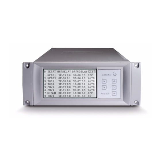
XGS-600 Gauge Controller XGS-600 Front and Back Description The display is biased so as to be best viewed from directly in front or slightly above. Figure 1-1 XGS-600 Front Panel Figure 1-2 Backplate Connections Front/Rear Panel Components Item Description Page Display See “Screen Flow”... -
Page 13: Unit Dimensions
XGS-600 Gauge Controller Unit Dimensions Figure 1-3 shows the unit dimensions with mm in brackets. Figure 1-3 XGS - 600 Dimensions... - Page 14 XGS-600 Gauge Controller This page intentionally left blank.
-
Page 15: Installation
XGS-600 Gauge Controller Chapter 2: Installation Each XGS-600 unit is inspected and carefully packed prior to shipment. If the unit arrives damaged, save the packing materials and immediately notify the carrier. Because the packing materials are designed specifically for this instrument, always use them when transporting the unit. - Page 16 3. Turn on the unit using the rear panel power switch. NOTE Gauges and accessories are available for the XGS-600 controller such as rack mount hardware, gauge and I/O cables, and a tilt stand. See Table 2-1 and Table 2-2.
- Page 17 XGS-600 Gauge Controller Table 2-2 Gauge Selection Chart Controller Gauge Card Gauge Type Recommendation Gauge Characteristics ✔ ConvecTorr Best overall convection gauge • Stainless steel for accuracy repeatability, • Pipe thread, KF and CFF secure connection • Locking bayonet connector ✔...
- Page 18 BA Cross Reference The XGS-600 controller is compatible with many competitor gauges. Table 2-3 indicates which Varian gauge setting should be used for each of these gauges. See “Sensor Setup Screen” on page 3-9. Table 2-3 BA Cross Reference...
- Page 19 XGS-600 Gauge Controller Table 2-3 BA Cross Reference (Continued) Huntington Kurt Lesker Duniway Select Sensor model 571 for the following: 274002 4336-P IGT-075 IP-100 G075F I-075-N 274003 4336-K IGT-100 IK-100 G100F I-075-P 274005 4336-F IK-100-F G100KQF25 I-075-K 274006 4336-P/1 IP-150...
- Page 20 XGS-600 Gauge Controller This page intentionally left blank.
-
Page 21: Operating Instructions
XGS-600 Gauge Controller Chapter 3: Operating Instructions Operational Screens Screen Flow Figure 3-1 shows the screen flow. Main See page 3-3 Press SETPTS Press LARGER Press EXIT Press EXIT Large Font Setpoints Press SETUP See page 3-16 See page 3-7... - Page 22 XGS-600 Gauge Controller General Navigation and Data Entry Use navigation keys to locate cursor on an area of interest (ex. data entry, gauge control or screen navigation soft key). Only fields that are user-variable are accessible by the cursor. Hold the key pressed for faster cursor movement.
- Page 23 XGS-600 Gauge Controller Main Screen Figure 3-2 shows the main screen, which appears at power up. NOTE The sequence of gauge rows follows the board installation sequence from left to right (when viewed from the front). Use this screen to: ❑...
- Page 24 XGS-600 Gauge Controller Sensor ID’s Lists the five-character User Label configured on the “Sensor Setup Screen” on page 3-9. Auto-On Indicator Indicates Auto-On has been set up, using the Sensor Setup screen, between a convection and an ion gauge(s). The same symbol appears next to both the convection and the ion gauge showing the link between the two.
- Page 25 Fil1 or Fil2. Turning off degas momentarily turns off emission. CAL (CNV only): Convection TC gauges are calibrated using this control. The XGS-600 uses Varian's Smart Cal, which automatically determines whether to perform a vacuum calibration or atmosphere calibration based on the pressure presented to the sensor.
- Page 26 XGS-600 Gauge Controller NOTE Convection gauge calibration at atmosphere depends on orientation. Be sure to install the gauge sensor in final orientation before calibrating. To calibrate: 1. Cursor down to the CAL control for the required gauge. 2. Present either vacuum or atmospheric pressure to the gauge.
- Page 27 ON reading must be a lower pressure than the OFF reading or an error (ERR) warning appears in the rightmost column. Once valid settings are entered, ERR changes to AUTO. See Appendix Appendix A. “XGS-600 Gauge Specifications” on page A-1 for setpoint output specifications and setpoint connector pin-outs.
- Page 28 XGS-600 Gauge Controller Select a Setpoint OFF pressure value. If the sensor pressure rises above this value, the rear panel output de-activates (voltage high) and the Setpoint # clears from the Main screen. The OFF reading must be a higher pressure than the ON reading or an error (ERR) warning appears in the rightmost column.
- Page 29 XGS-600 Gauge Controller Sensor Setup Screen To open this screen select SETUP on the Main screen. Figure 3-4 Sensor Setup Screen: HFIG and IMG Sensors Figure 3-5 Sensor Setup Screen: CNV (Convection) Sensors - - - See Table 3-1 on page 3-11 for default values. Fields that are unavailable have...
- Page 30 XGS-600 Gauge Controller Sensor ID Use this field to select the sensor to view its setup parameters. Displays the unique system-assigned gauge identification. Scroll through this list to select a sensor and the remainder of fields on the screen populate with its present settings.
- Page 31 XGS-600 Gauge Controller Table 3-1 Default Setup Values by Ion Gauge Type Over- Default HFIG Default Emis Default pressure Degas Power Number of Sensor Model Current (ma) Sensitivity limit (mT)+ (mA) Filaments MBA100 1-10 mT* MBA200 1-10 mT* 1-10 mT*...
- Page 32 This causes the pressure to decrease to where the controller again raises the current, and the system can get stuck in this cycle. You can defeat this by setting the emission current to 1.0 ma or less, so the XGS-600 maintains that constant emission current at all pressures.
- Page 33 5 mTorr, especially if a large volume of gas is being pumped. The XGS-600 allows you to program a threshold pressure as high as 1 Torr. When Auto-ON is being used, the gauge overprotection feature is still active to protect the high vacuum gauge.
- Page 34 XGS-600 Gauge Controller System Setup Screen Use this screen to set values for overall system operation. To open this screen select SYSTEM SETUP on the Sensor Setup screen. Figure 3-6 System Setup Screen UNITS Select: Torr (default), Pascal or mbar. Once the units are changed, the values throughout the system are updated to the new units.
- Page 35 SERIAL MODE Select between RS232 or RS485 serial transceivers. RS232 and RS485 have separate outputs on the rear panel Serial connector (see Appendix Appendix A. “XGS-600 Gauge Specifications” on page A-1). SERIAL BAUD RATE Selects between baud rate options: 9600 (default) and 19200.
- Page 36 XGS-600 Gauge Controller Large Font Screen To open this screen select LARGER on the Main screen. Figure 3-8 Large Font Screen The leftmost column shows the User Label as configured on the Sensor Setup screen. You can select which transducers appear on this screen by moving the cursor to the User Label and using the +/- modify keys.
-
Page 37: Service And Troubleshooting
FRONT Figure 4-1 XGS-600 Slot Numbers ❑ Slots are numbered from left to right as viewed from the front of the XGS-600. ❑ Option slots 1 though 4 are “Long, High Profile Slots” and can accommodate any board. HFIG boards are “Long, High Profile” boards and can only be installed in slots 1 through 4. - Page 38 6. Sensor Board Replacement Procedure WARNING Only trained service personnel should attempt this work. Disconnect the XGS-600 mains connection by unplugging the IEC power cord from the back of the unit before removing the unit's cover. CAUTION Wear an ESD bracelet and observe all appropriate precautions to avoid damage to PCBs.
- Page 39 Install a filler plate by installing the two hooks into the case bottom and snapping in the foot. Contact Varian if additional fillers are needed. 5. Install the replacement board: a. Place the end of the board into the end guide (Figure 4-3).
- Page 40 XGS-600 Gauge Controller c. Locate the rear panel portion of the board into its slot, press down the tab and exert gentle pressure until it clicks into place. CAUTION Do not force the board down. If too much pressure is required the connector pins are not aligned.
-
Page 41: Troubleshooting
XGS-600 Gauge Controller Troubleshooting Error Codes Table 4-1 General Error Code Error Message Meaning Cause Action BD COM Board Comm: Motherboard and sensor 1. Cycle power to unit Internal board stopped 2. Return unit for repair communication communicating error ❑... - Page 42 XGS-600 Gauge Controller Tips Varian offers reference ionization B/A gauges, which are sealed off at approximately 5E–6 Torr/6.6E–4 Pa, as well as a Convection gauge simulator which can switch between atmosphere and vacuum simulation. These devices are extremely helpful in troubleshooting a vacuum system problem by isolating the defective component.
- Page 43 Fil1 before attempting to degas that filament 3. Attempted to degas third gauge 3. XGS-600 will only degas two gauges at a time 4. Finish a degas before attempting to start a third The front panel display indicates Time delay = 0.0, 0.1...
- Page 44 XGS-600 Gauge Controller Table 4-2 Troubleshooting (Continued) Problem Cause Action BDCOMM message appears on A major EMI disturbance or Cycle AC (mains) power to the one or more channels and stays other anomaly has caused a unit OFF and ON again to...
-
Page 45: Appendix A. Xgs-600 Gauge Specifications
XGS-600 Gauge Controller Appendix A. XGS-600 Gauge Specifications Instrument Specifications Table A-1 provides the XGS-600 instrument specifications. Table A-1 General XGS-600 Gauge Specifications Specification Description Display Type: Backlit dot matrix monochrome LCD Backlight: White LED Small Font mode: Up to 8 channels displayed simultaneously... - Page 46 XGS-600 Gauge Controller Table A-1 General XGS-600 Gauge Specifications (Continued) Specification Description Mains Power and Cordage Voltage: 100-120, 200-240 VAC ±10% 50/60 HZ, 2A Available worldwide IEC cords Environmental/Installation Storage Temperature: -15 to 70° C Operating Temperature: CSA certified 5 to 40° C, at 5 to 95% RH,...
-
Page 47: Board Specifications/Descriptions
Bayard-Alpert type hot filament ionization gauges including nude UHV types. The board can be set up for all Varian hot filament gauges and allows you to set gauge emission current, sensitivity value, and gas correction factor. The UHV range and E-Beam degas are standard, as is dual filament control, remote I/O control of emission and filament selection, and 0 to 10 V analog output. - Page 48 ❑ and select calibration for air or argon. Calibration is Varian's Smart Cal that determines whether a CAL command is for vacuum or atmosphere. Remote control of calibration and analog output is standard. Each channel has its own 9-pin Dsub connector.
- Page 49 300’ using Varian TC or ConvecTorr cable IMG Board The IMG board operates Varian IMG-100 and IMG-300 gauges and allows you to set gauge sensitivity value, and gas correction factor. The UHV range is standard, as is remote I/O control of emission and 0 to 10 V analog output.
-
Page 50: I/O Pin Assignments
XGS-600 Gauge Controller I/O Pin Assignments Table A-5 through Table A-9 give the I/O pin assignments for the various boards and connectors. Table A-5 IMG Board I/O Pin Assignments Function Pin # (J26) EMIS ON ANALOG OUT STATUS OUT 2 + Shield... - Page 51 XGS-600 Gauge Controller Table A-8 Set-Point Connector Pin Assignments Function Pin # SET POINT 1 OUTPUT SET POINT 2 OUTPUT SET POINT 3 OUTPUT SET POINT 4 OUTPUT SET POINT 5 OUTPUT SET POINT 6 OUTPUT SET POINT 7 OUTPUT...
-
Page 52: Xgs-600 Vs Multigauge And Sentorr Backwards Compatibility Detail
RS232, and is not backwards compatible with the MultiGauge and SenTorr Mini-DIN connectors. Non-Backwards Compatible Features The significant changes with the XGS-600 vs MultiGauge and SenTorr are the following: ❑ XGS-600 does not have a 4 channel TC card (MG) ❑... - Page 53 SenTorr uses terminal block connectors while MultiGauge uses a 25-position Dsub. ❑ XGS-600 is not available in a Black Box version with a remote mountable display. Table A-10 list the features compatible for the MultiGauge and SenTorr units. Table A-10 Feature Compatibility Table...
- Page 54 XGS-600 Gauge Controller Table A-10 Feature Compatibility Table (Continued) SenTorr BA or Feature XGS-600 MultiGauge SenTorr CC RS232 Std Dsub9 IBM Opt Dsub9, IBM Opt Dsub9, IBM Opt Dsub9, IBM pinout, pinout pinout pinout supports MG protocol RS485 Std in Dsub9,...
-
Page 55: Appendix B. Serial Commands
The following characters are used in Table B-1: Command Description Notes All commands to the XGS-600 must begin with the character "#". RS485 Address =00 for RS232 (system default). Max allowable: 20hex Command Each command is identified by a unique command number, 2 Number hex digits, 01-FF. - Page 56 Responses are also terminated with < CR >. The XGS-600 sends ?FF as a response if the command or data is invalid, or if the command length is incorrect. There is no response to a wrong address, or lack of termination character.
- Page 57 XGS-600 Gauge Controller Table B-1 Serial Command Set (Continued) Response from Description Command XGS-600 Notes Set pressure units to #aa10 > Torr Set pressure units to #aa11 > mBar Set pressure units to #aa12 > Pascal Read pressure units #aa13 >xx...
- Page 58 XGS-600 Gauge Controller Table B-1 Serial Command Set (Continued) Response from Description Command XGS-600 Notes Read Auto-On #aaB1cn >cnx.xExx where cn is Ion Gauge. where cn is the TC. Ion Gauge Commands (HFIG and IMG gauges) Assign Tube Type to #aa16cnxx >...
- Page 59 XGS-600 Gauge Controller Table B-1 Serial Command Set (Continued) Response from Description Command XGS-600 Notes Read Filament Lit #aa34cn >xx where: xx = 01 is Filament 1 xx = 02 is Filament 2 Set Auto Fil Advance #aa35 > Set Auto Fil Advance #aa36 >...
- Page 60 XGS-600 Gauge Controller Table B-1 Serial Command Set (Continued) Response from Description Command XGS-600 Notes Set Sensitivity #aa55cnxx.xx > This sensitivity value must always be in Torr due to xx.xx format restriction. Note however the value displayed on front panel is in Torr, mbar, or Pascal.
- Page 61 XGS-600 Gauge Controller Table B-1 Serial Command Set (Continued) Response from Description Command XGS-600 Notes Read Setpoint #aa5Fh >x OFF/ON/Auto where h is setpoint where x is state: number 1-8 0 = OFF (manual override) 1 = ON (manual override)
- Page 62 ❑ Commands which apply to Multi-Gauge/SenTorr but do not apply to the XGS are ignored by the XGS-600. There is no response and no error message. ❑ Any commands (ex. # 56-59) referring to a gauge or sensor type that is not supported...
- Page 63 2. Select Programs > Accessories > Communications > HyperTerminal. 3. Double-click Hypertrm.exe. The Connection Description dialog box appears. 4. Enter a name and choose an icon for the connection, for example: XGS-600 RS-232. 5. Click OK. The Connect To dialog box appears.
- Page 64 XGS-600 Gauge Controller ❑ Click Configure and verify the port settings are correct. 11. Ensure that the Settings tab is configured as follows: ❑ Terminal keys radio button selected. ❑ Ctrl+H radio button selected. ❑ Auto detect selected from the Emulation pull-down list.
-
Page 65: Appendix C. Gas Correction Factor Table
Center, NASA Technical Note TND-5285, National Aeronautics and Space Administration, Washington, DC, June 1969. To automatically convert readings of the XGS-600 Controller, normally calibrated for nitrogen, to read pressures of the other gasses: 1. Use Sensor Setup to access the GAS CORRECTION function. - Page 66 XGS-600 Gauge Controller Table C-1 Gas Correction Factor Table...
- Page 67 XGS-600 Gauge Controller Table C-1 Gas Correction Factor Table (Continued)
- Page 68 XGS-600 Gauge Controller This page intentionally left blank.
- Page 70 Japan Fax: +33 (0) 1 69 86 29 88 Tel: (81) 3 5232 1253 (dedicated line) Mexico vtj.technical.support@varianinc.com Benelux Varian, S. de R.L. de C.V. Varian Vacuum Technologies Concepcion Beistegui No 109 Korea Herculesweg 8 Col Del Valle Tel (82) 2 3452 2452 (dedicated line) 4338 PL Middelburg C.P.
Need help?
Do you have a question about the XGS-600 and is the answer not in the manual?
Questions and answers