
Related Manuals for Varian sentorr


Summary of Contents for Varian sentorr
- Page 1 Varian Vacuum Technologies 121 Hartwell Avenue Lexington, Massachusetts 02421 (781)861-7200 senTorr ™ Gauge Controller Instruction Manual Manual No. 6999-08-165 Revision G February 1999...
- Page 2 FAX ....(82) 3-333-665-0115 Telephone ....(44) 932-234-741 FAX ....(44) 932-228-769 Copyright © by Varian Associates, Inc. Reserved, including the right of reproduction in whole or in part in any form, without permission in writing from Varian Vacuum Products, Lexington, MA 02421 November, 1995...
- Page 3 Varian Associates for repair and/or replacement. Except as stated herein, Seller makes no warranty, express or implied (either in fact or by operation of law), statutory or otherwise;...
- Page 4 Every operator or ser- vice person must read and thoroughly understand operation/maintenance manuals and any additional information provided by Varian Associates. All warnings and cautions should be read carefully and strictly observed. Consult local, state, and national agencies regarding specific requirements and reg- ulations.
- Page 5 WARNING _____________ Check that your Ion Gauge Controller and vacuum system are sepa- rately grounded to a common ground. Placement of a ground wire between the vacuum chamber and the con- troller chassis is not safe; large continuous currents could flow through it. Personnel could be killed by high voltages (160 to 900 volts may be pre- sent in an improperly grounded system).
- Page 6 WARNING _____________ This equipment contains high voltages (up to 3000 volts), high enough to produce electric shock and cause death or serious injury. Equipment utilizing these controls should be designed to prevent per- sonal contact with high voltages. Always break the primary circuit when direct access to the control unit is required.
-
Page 7: Table Of Contents
Table Of Contents Page SAFETY CONSIDERATIONS ..........INTRODUCTION AND DESCRIPTION . -
Page 8: Introduction And Description
One Bayard-Alpert gauge tube One Cold Cathode gauge tube The senTorr Gauge Controller features one digital display per gauge tube. The displays are LED-driven providing clear and sharp pressure readings. The front panel keypad has practical lockout features that protect against unauthorized parameter inputs. Analog outputs and remote capabilities are located on the back panel. - Page 9 Introduction and Description Varian cannot guarantee compliance with FCC regulations for radiated emissions unless all external wiring is shielded. (See page iii) HFIG Gauge (BA2, BA2c, BA, UHV, UHV2c models) Minimum pressure 1.3 x 10 Pa/1 x 10 Torr (BA) capability 5.3 x 10...
-
Page 10: Front Panel
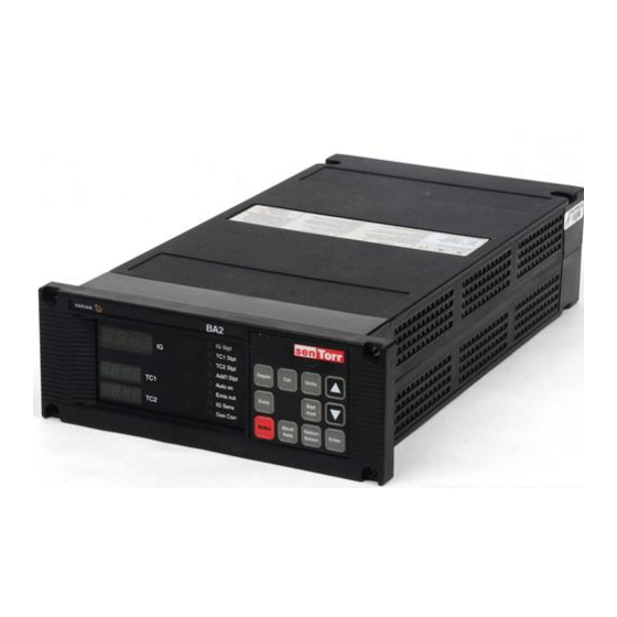
RS232 or RS485/422 FRONT PANEL The front panel display of the senTorr 7-segment, LED digits and LED annunciators. These provide con- tinuous, crisp readings, with no directional bias. The display uses three LED colors to group information. Green pressure data and parameter values... - Page 11 A single pressure display features four digits, two for the mantissa and two for the exponent. There is a pressure readout for each gauge, with the Bayard-Alpert or Cold Cathode display labeled “IG” and the two thermocouple or ConvecTorr displays labeled “TC1” and “TC2” , as applicable to the senTorr model. Label...
-
Page 12: Part Numbers And Descriptions
The senTorr offers computer interface options allowing complete operation of the unit remotely via ser- ial link. The RS232 option consists of a plug-in printed circuit board (Varian part no. L9141301) avail- able with either a 9-pin, D-subminiature connector or fiber optic connectors (fiber-optic board, Varian part no. - Page 13 Introduction and Description...
-
Page 14: Preparation For Use
PREPARATION FOR USE UNPACKING Each senTorr unit is inspected and carefully packed prior to shipment. If the unit arrives damaged, save the packing material and immediately notify the carrier. Because the packing materials are designed specifically for this instrument, they should always be used when transporting the unit. The shipping container is packed with the following contents. - Page 15 Preparation for Use Figure 2-1. Setting Line Voltage Figure 2-2. Rear Panel Connections...
- Page 16 Preparation for Use Figure 2-3. Panel Cutout Dimensions Note: Bezel Trim Kit R0130301 can be used to hide gaps between senTorr case and panel)
- Page 17 Preparation for Use...
-
Page 18: Operation
Refer to Figure 3-1 for the locations of the keys and display features described in following paragraphs. Following each key name are the senTorr models and the option (if any) to which the function applies. Note that some of the keys may not work unless a particular option has been installed. -
Page 19: Emis Key (All Models)
Emis Key (BA/UHV dual filament models) Pressing the “Enter” key before pressing “Emis” uses the second filament. Figure 3-1. Front Panel, senTorr Gauge Controller Baud Rate Key (All Models) This key is used to display and set the serial communications baud rate, parity, and the controller address (for use in a multi-drop communication link. -
Page 20: Parameter Programming
The set point and ion gauge parameters listed in a column on the front panel display (see Figure 3-1) can be viewed or programmed by putting the senTorr into the Program mode. To the left of each para- meter is a single yellow LED. - Page 21 9.9 mA. The default setting is 4 mA for standard gauges and 0.1 mA for broad-range Bayard- Alpert gauges (Varian models 564 and 580). If the emission current is set less than or equal to 1.0 mA, it remains constant over all pressures. If the emission current setting is greater than 1.0 mA, it will be automatically reduced to one-tenth of the set-...
-
Page 22: Set Point Hysteresis
Operation SET POINT HYSTERESIS A set point will energize when the pressure of its pre-assigned gauge drops below the set point's pro- grammed threshold pressure. The set point will de-energize when the gauge pressure rises above the set point hysteresis pressure. The set point hysteresis automatically defaults to 10 percent above the threshold value. -
Page 23: Recorder Output
Recorder output for each gauge is provided at the back of the unit. A two-conductor Micro Jax con- nector is plugged into each output. Varian strongly recommends the use of shielded wiring (coaxial cable) to maintain compliance with FCC regulations for radiated emissions. Refer to Figure 3-3 to assemble the cable. - Page 24 Operation Figure 3-4a. Standard Recorder Output Characteristics...
- Page 25 Operation Optional Linear recorder output for TC configuration (requires optionally puchased firmware) Pressure Pressure Voltage ≥133 Pa ≥1E +0 Torr 1.3 E1 Pa 1E-1Torr 6.6 Pa 5E-2Torr 1.3 Pa 1E-2Torr ≤1.3E-1 Pa ≤ 1E-3Torr 0.01 Error E03 Error E03 10.156 (over scale) Linear recorder output option for BA and CC configurations Full Scale Full-Scale...
-
Page 26: Tc And Convectorr Calibration
Repeat the procedure for each TC at each end point. ACCESS CODES The senTorr offers several hidden features available through the keypad. This provides some protec- tion for the operator and the system by requiring knowledge of the access code for the desired func- tion. -
Page 27: Display Test
3-10 BATTERY BACKUP The senTorr uses a lithium battery and CMOS RAM for storage of all system parameters during power outages or when powered down. Upon restoring power, the senTorr verifies the RAM content. If the RAM is good, the parameters will remain as previously saved; if the RAM is corrupted, all parameters will be reset to their default values. -
Page 28: Troubleshooting
TROUBLESHOOTING GENERAL These troubleshooting procedures are provided to aid the operator in identifying failure modes. For fur- ther troubleshooting assistance or for the replacement of a board or unit, contact Varian Vacuum Products Service at 1-800-882-7426. ERROR CODES O2 E Pressure burst caused by a sudden rise in pressure at the ion gauge. -
Page 29: Application Footnotes
Enter the Program mode by pressing the “Option select” key. The first available parameter, beginning from the top of the column and depending on the senTorr model and options installed, will flash in the appropriate gauge display. Repeated “Option Select” key presses will advance through the parameters,... -
Page 30: Programming Emission Ma
Enter the Program mode by pressing the “Option Select” key. The first available parameter, beginning from the top of the column and depending on the senTorr model and options installed, will flash in the appropriate gauge display. Repeatedly pressing the “Option Select” key will advance through the para- meters, returning the unit to the Run mode after the last key press. -
Page 31: Programming Sensitivity
Enter the Program mode by pressing the “Option Select” key. The first available parameter, beginning from the top of the column and depending on the senTorr model and options installed, will flash in the appropriate gauge display. Repeatedly pressing the “Option Select” key will advance through the para- meters, returning the unit to the Run mode after the last key press. -
Page 32: Appendix A Gas Correction Factor Table
5285, National Aeronautics and Space Administration, Washington, DC, June 1969. To automatically convert readings of the senTorr Controller (normally calibrated for nitrogen), enter the relative gas correction constant through the front panel key function GAS CORR. By entering the gas constant, the gauge will divide the result by the gas correction constant and display the correct adjusted value. - Page 33 Appendix Gas Correction Factor Table Relative Ionization Gauge Relative Ionization Gauge Substance Formula Gas Correction Factor Substance Formula Gas Correction Factor Carbon Disulfide Acetaldehyde Acetone Carbon Monoxide 1.05 1.05 Acetylene Carbon Tetrachloride Cesium 0.98 Ammonia Chlorine 0.68 Amylene: · · Chlorobenzene ·...
- Page 34 Appendix Relative Ionization Gauge Relative Ionization Gauge Substance Formula Gas Correction Factor Substance Formula Gas Correction Factor Ethyl ether Naphthalene Neon 0.30 Ethylene 0.31 Nitrobenzene Nitrogen 2.2 to 2.5 · · · Ethylene oxide Nitrotoluene (o Helium 0.18 Nitric Oxide 0.15 0.13 0.12...
- Page 35 In compliance with Federal OSHA Safety Standard 1910.1200, Hazard Communications “Right to Know” , Varian is enforcing that standard to preclude the potential health risk to its service person- nel that can occur when receiving, disassembling, or repairing potentially contaminated products.
- Page 36 121 Hartwell Avenue Lexington, MA 02421 All products sold by Varian and returned by customer are subject to Varian Vacuum Products standard terms and conditions of sale including, but not limited to, the warranty and damages and liability provi- sions set forth in the warranty.
Need help?
Do you have a question about the sentorr and is the answer not in the manual?
Questions and answers