Prior Scientific ProScan III Manual
Universal microscope automation controller
Hide thumbs
Also See for ProScan III:
- Manual (2 pages) ,
- Quick start instructions (2 pages) ,
- Manual (2 pages)
Table of Contents
Advertisement
ProScan
Universal Microscope Automation Controller
Manual Version 1.12
®
III
Worldwide distribution
Prior Scientific, Ltd
Prior Scientific, Inc
Cambridge, UK
Rockland, MA. USA
T. +44 (0) 1223 881711
T. +1 781-878-8442
E. uksales@prior.com
E. info@prior.com
ProScan® III Manual
Visit Prior on the web at
Prior Scientific, GmbH
Prior Scientific KK
Jena, Germany
Tokyo, Japan
T. +49 (0) 3641 675 650
T. +81-3-5652-8831
E. jena@prior.com
E. info-japan@prior.com
Visit Prior on the web at
prior.com
1
prior.com
Advertisement
Table of Contents

Related Manuals for Prior Scientific ProScan III


Summary of Contents for Prior Scientific ProScan III
- Page 1 ProScan Universal Microscope Automation Controller ProScan® III Manual Manual Version 1.12 prior.com Visit Prior on the web at Worldwide distribution Prior Scientific, Ltd Prior Scientific, Inc Prior Scientific, GmbH Prior Scientific KK Cambridge, UK Rockland, MA. USA Jena, Germany Tokyo, Japan T.
-
Page 3: Table Of Contents
ProScan® III Manual Contents SECTION 1 IMPORTANT SAFETY INFORMATION SECTION 2 IDENTIFYING AND CONNECTING YOUR SYSTEM .1 Identifying the parts of the ProScan III controller 2.2 Connections 2.3 Installing accessories and indicators 2.31 Installing stages 2.32 Installing focus 2.33 Installing filter wheels and shutters 2.34 Fourth Axis or Auxiliary Axis equipment... - Page 4 Appendix I: ProScan III FTDI USB Field Issues and Solution Thank you for purchasing a ProScan III system – we hope and expect that it will be a reliable and useful part of your microscopy set up. Please take the time to thoroughly read this manual before installing and using the ProScan III as it contains both important safety information and how to use the device effectively.
-
Page 5: Section 1 Important Safety Information
For use in a manner not specified in this manual contact Prior before any work is done. To reduce the risk of damage, unplug the product from the power source before connecting the components together. © Prior Scientific Instruments Ltd Version 1.12 June 2017 Page 3... - Page 6 The ProScan III is class 1 and must be only connected to a power outlet which provides a protective earth (ground).
- Page 7 This manual covers all varieties of the ProScan III controller produced by Prior Scientific. It also covers the control, via the ProScan III, of any Prior product which is compatible with the ProScan III, including the control joystick, filters, shutters, focus motors, the ProZ stand, the Brightfield LED, the linear stage, the Z-Deck and the stepper motor stage, will be covered by this manual.
-
Page 8: Section 2 Identifying And Connecting Your System
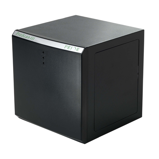
(right) option. For the purposes of this manual we will use the vertical version in pictures and instructions below; however the instructions apply equally to the horizontal version. The large, square box is the main ProScan III unit, whilst the smaller box is an ancillary box for added functionality. -
Page 9: Connections
1. POWER: Green illuminated: Power On 2. TX/RX: Two Colour LED communications a. RX (Receive) Amber illuminated b. TX (Transmit) Green illuminated 3. STATUS: Red illuminated: Fault in system. Contact Prior Scientific. © Prior Scientific Instruments Ltd Version 1.12 June 2017 Page 7... -
Page 10: Installing Accessories And Indicators
If you have an encoded stage, plug and screw in the encoder cables, these are labelled X and Y. Ensure the X cable is plugged into the connector on the ProScan III labelled X and ensure the Y cable is plugged into the Y labelled connector. Power on the ProScan III. The ProScan III will now auto detect the stage and setup the features associated with that stage in its software. -
Page 11: Installing Focus
The following instructions refer to the standard split sleeve mounting standard PS3H122 focus motor with the appropriate microscope specific focus sleeve adapter. For specific microscopes, contact Prior Scientific, or enter the ‘Download Centre’ on the Prior Scientific website and open the ‘Help Sheets and Installation Instructions’ section, which provides instructions for a range of microscopes. - Page 12 Interactive Control Centre settings menu or by using Prior Terminal and changing the settings of the ZD command via RS232 or USB communication. © Prior Scientific Instruments Ltd Version 1.12 June 2017 Page 10...
-
Page 13: Installing Filter Wheels And Shutters
Wheels and Shutters are manufactured with C mount threads. The addition of a male to male C mount adapter (Part No. HF207) allows these units to be mounted to a microscope camera port, if required. © Prior Scientific Instruments Ltd Version 1.12 June 2017 Page 11... -
Page 14: Fourth Axis Or Auxiliary Axis Equipment
Lumen 15 way connectors. The shutter connector is optional and should be connected to the ProScan III “S1, S2 or S3”. Switch off the power using the power switch. Connect and firmly and screw in the cable both at the controller and Lumen 200Pro connector. -
Page 15: Expanding The Proscan
Note that the ancillary box is not a standalone unit. Depending on whether a V- or H- type ProScan III was purchased, the ancillary box is added to the top or the side respectively of the main box. - Page 16 ProScan® III Manual First remove the screws (circled in green) from the main unit and ancillary unit. Place the screws in a safe place © Prior Scientific Instruments Ltd Version 1.12 June 2017 Page 14...
- Page 17 Then install the panel you removed from the main casing onto the appropriate open side of the ancillary casing. © Prior Scientific Instruments Ltd Version 1.12 June 2017 Page 15...
- Page 18 Ensure that the cables are threaded through the opening between the two cases; otherwise it will not be possible to place the boards back into their cases. © Prior Scientific Instruments Ltd Version 1.12 June 2017...
- Page 19 Slide circuit boards back into their cases – ensure that they go all the way back in (the prongs at the end should enter the slots at the back of the cases). Then redo the screws. Your ProScan III is now ready for use. © Prior Scientific Instruments Ltd Version 1.12 June 2017...
-
Page 20: Section 3 Installing And Using The Software
SECTION 3 3.1 Installing and Opening Software. Prior supplies free software which can be used to control the ProScan III system. It is available in either 32 or 64 bit versions. It can be downloaded by going to the ‘Downloads’... -
Page 21: Using The Program
3 = Status Area 4 = Measurement Area 5 = Shutters 6 = Pattern 7 = EMERGENCY STOP 8 = Joystick 9 = Stage 10 = Focus 11 = Filters/4 axis control © Prior Scientific Instruments Ltd Version 1.12 June 2017 Page 19... - Page 22 X value using encoder (Based on the encoder settings) Y value using encoder (Based on the encoder settings) No z-encoder fitted, Z position. (in microns, if the UPR is set correctly for the microcope). © Prior Scientific Instruments Ltd Version 1.12 June 2017 Page 20...
- Page 23 Click buttons to move stage set distances (default 1000um). Back, Forward (Y) Left, right (X) Right click with mouse on one of the buttons to set the distance travelled. © Prior Scientific Instruments Ltd Version 1.12 June 2017 Page 21...
- Page 24 Limits: Displays eight digits, one for each end of each axis, 0 is not active 1 is limit active. All digits are always displayed in the following order: A-, A+, Z-,Z+,Y-,Y+, X-,X+. Shutters Area: © Prior Scientific Instruments Ltd Version 1.12 June 2017 Page 22...
- Page 25 Click the ‘Home Shutter’ to home the shutter; this should be done on start-up. ‘Auto Cycle’, click to automatically cycle the unit through 0-100% light output, Click cancel to stop. Bulb Power: Switches entire Lumen On/Off © Prior Scientific Instruments Ltd Version 1.12 June 2017 Page 23...
- Page 26 Stop: Press this button to stop all axis movement immediately. Pattern: Click the ‘Pattern’ button the launch Pattern Manager. Joystick: Click Joystick to launch the Joystick windows. Drag the black ball to make the axis move. Menu Functions: © Prior Scientific Instruments Ltd Version 1.12 June 2017 Page 24...
- Page 27 Focus Current: Sets the running current for the motors on the focus between 0 and 1.5Amps. WARNING: Changing this value may damage your motors. Filter Current: © Prior Scientific Instruments Ltd Version 1.12 June 2017 Page 25...
- Page 28 1 revolution.This enables the micron value in the display to be related correctly to the attached microscope. Speed Menu: Stage Speed: © Prior Scientific Instruments Ltd Version 1.12 June 2017 Page 26...
- Page 29 Changes the characteristics of the selected filter axis. Speed, 1-100%. Acceleration 4-100% Curve (See S-Curve in Appendix D) 1-100% WARNING: Filter axis may stall under certain settings. Joystick Enable: Enables or Disables Joystick, check to enable. © Prior Scientific Instruments Ltd Version 1.12 June 2017 Page 27...
- Page 30 Host Y reverse: Check to reverse the direction of the Y axis under computer control. Host Z reverse (Focus): Check to reverse the direction of the Z (Focus) axis under computer control. Backlash Menu: Stage Host Backlash Distance: © Prior Scientific Instruments Ltd Version 1.12 June 2017 Page 28...
- Page 31 Focus Host Backlash Enable: Check this to enable the backlash feature for computer control on the focus axis. Encoder Menu: Stage Encoders Enable: Check this to enable the encoders to function with the stage. © Prior Scientific Instruments Ltd Version 1.12 June 2017 Page 29...
- Page 32 Focus Servo Enable: Check this to enable focus servo. This is make the focus attempt to stay at the programmed position. Use this function to overcome drift in time-lapse experiments. © Prior Scientific Instruments Ltd Version 1.12 June 2017 Page 30...
- Page 33 Z Resolution: Sets the encoder resolution for the Z axis, this determines the micron number displayed in the DRO. Use negative number to reverse the direction if encoder reversed. © Prior Scientific Instruments Ltd Version 1.12 June 2017 Page 31...
- Page 34 All point mapping). 4-point Stage Correction: Check to enable IST stage correction. Skew Correction: Enables Basic Skew correction using the parameters from Skew Angle, Skew About and Skew Second. © Prior Scientific Instruments Ltd Version 1.12 June 2017 Page 32...
- Page 35 If the Piezo drive is daisy chained from the PS3 controller then it will be connected to immediately. If it is attatched to the computer via another COM port, click ‘Yes’. © Prior Scientific Instruments Ltd Version 1.12 June 2017...
- Page 36 Supported Functions are: Lumen Attenuator, move to % open. Filter wheels: move to Next, Previous, Home and Move to position. Shutter: Open and Close. XYZ axis: Relative and Absolute Moves. © Prior Scientific Instruments Ltd Version 1.12 June 2017 Page 34...
- Page 37 Type in the % of light you would like the lumen attenuator to allow through. e.g., Type in the relative move you would like the stage to make and then click add. © Prior Scientific Instruments Ltd Version 1.12 June 2017 Page 35...
- Page 38 The pattern manager is designed to drive the stage in various patterns, with the TTL trigger functions enabled this can be used to automatically gather images for tilling or stitching. Click the ‘Pattern Button’ on the main screen of the program. © Prior Scientific Instruments Ltd Version 1.12 June 2017 Page 36...
- Page 39 Top – Snake Middle – Raster Bottom - Circle (Not shown): User, where user pattern is defined as a number of user points which are followed in order. © Prior Scientific Instruments Ltd Version 1.12 June 2017 Page 37...
- Page 40 Autofocus: the function is not available. Focus Range: the function is not available. Repeats: The number of times the pattern should be repeated. © Prior Scientific Instruments Ltd Version 1.12 June 2017 Page 38...
- Page 41 For the User pattern you must now add the points. Move to the location of a point you require for the user pattern and click New Point. Give the point a name and click ok. Repeat this for each user point. © Prior Scientific Instruments Ltd Version 1.12 June 2017 Page 39...
- Page 42 When exiting you will be prompted to save any unsaved patterns. To enable the TTL pulse on pattern move or to have a TTL signal while the stage is moving, see the TTL section above. © Prior Scientific Instruments Ltd Version 1.12 June 2017 Page 40...
-
Page 43: Section 4 Software Commands
Queue Full) will be returned. This indicates that the command has not been accepted and must be re-sent when the queue is no longer full. It is desirable to read back each individual command response (R<cr>) before sending any further commands. Sending © Prior Scientific Instruments Ltd Version 1.12 June 2017 Page 41... - Page 44 To stop the soak test enter an action and the unit will complete the current cycle and then stop. © Prior Scientific Instruments Ltd Version 1.12 June 2017 Page 42...
- Page 45 1 SOAK start the soak Note MACRO and SOAK can only be used in Standard Mode (COMP,0) 4.1.1 Axis Identification Axis Name Axis Number A/F3 © Prior Scientific Instruments Ltd Version 1.12 June 2017 Page 43...
-
Page 46: General Commands
None eg 05 means +Y and +X have been hit. Reading this status clears it. © Prior Scientific Instruments Ltd Version 1.12 June 2017 Page 44... - Page 47 Report the Command protocol (Compatibility mode (1) or Standard 0 = Std mode (0)) COMP None 1 = Comp COMP,1 mode is default after a software upgrade or RESET of controller. © Prior Scientific Instruments Ltd Version 1.12 June 2017 Page 45...
- Page 48 DATE None Text string E.g. Prior Scientific Instruments ProScan H31XYZEF controller Version 0.95 compiled Feb 16 2016 13:43:31 Sets the reporting of error to ‘Human’ if h is 1 (readable text) else error codes ERROR are returned (see Error Description Table) Stops movement in a controlled manner to reduce the risk of losing position.
-
Page 49: Stage Commands
Moves Left by x steps. None Moves stage and focus to zero ( 0,0,0 ) Sets the speed of the stage under joystick control. s is percentage in range 1 to 100. © Prior Scientific Instruments Ltd Version 1.12 June 2017 Page 47... - Page 50 SAS. Range of c is 1 to 1000. Prior chooses to express curve in time units rather than units/s/s/s. So at default 100 setting curve time = 13ms. At 200 curve time = 6.5ms © Prior Scientific Instruments Ltd Version 1.12 June 2017 Page 48...
- Page 51 MOTOR, 2, 1=0 turns Y motor off. Axes are identified by their number or character: MOTOR NOTE: for stepper stages, turning motors off then on may result in a small position error © Prior Scientific Instruments Ltd Version 1.12 June 2017 Page 49...
- Page 52 Move the stage at constant velocity in X,Y as specified by parameters. Units are in microns/s. VS,0,0 will bring the stage to rest. This can be used to simulate a joystick operation from your application. © Prior Scientific Instruments Ltd Version 1.12 June 2017 Page 50...
-
Page 53: Z Axis Commands
If an encoder is present on the Z axis, the position is only set when the current position is in the encoder range (it must have been further down than it is currently). © Prior Scientific Instruments Ltd Version 1.12 June 2017 Page 51... - Page 54 ZPLANE,E then enables focus tracking across entire stage based on that plane. Move to any XY point and Z will move accordingly. ZPLANE,D disables focus tracking. ZPLANE None Returns zplane enabled status ‘a’ [0|1] © Prior Scientific Instruments Ltd Version 1.12 June 2017 Page 52...
-
Page 55: Filter Wheel Commands
Report the current filter wheel w maximum speed setting m Sets the current filter wheel w maximum speed to m in units of %. w, m Range is 1 to 100 © Prior Scientific Instruments Ltd Version 1.12 June 2017 Page 53... -
Page 56: Shutter Commands
Users should always read lines until the END is seen in Shutter Text string order to maintain compatibility. Example SHUTTER_1 = NORMAL DEFAULT_STATE=CLOSED © Prior Scientific Instruments Ltd Version 1.12 June 2017 Page 54... -
Page 57: Lumen Pro Commands
POWER , n current status. The Lumen 200PRO unit must be connected to the plug and play shutter output of a ProScan III. The Lumen will default to state 1, Lumen on, if no cable connected. © Prior Scientific Instruments Ltd Version 1.12 June 2017... -
Page 58: Pattern Commands
The stage then moves backwards to the top of the polygon and proceeds to move around the side of the polygon sides until all sides are done. © Prior Scientific Instruments Ltd Version 1.12 June 2017 Page 56... - Page 59 6. To query when the raster has finished, send “AS” command. A response of “1” indicates raster still running, a response of “0” indicates raster has finished. None Where n =0 indicating idle, n=1 indicating raster active © Prior Scientific Instruments Ltd Version 1.12 June 2017 Page 57...
-
Page 60: Stage Mapping Commands
Returns 4pt correction state S plus the four correction values CORRECT S,a,b,c,d 1 0.999851 0.000034 0.0 1.000184 All ProScan III stages come fitted with 4pt correction enabled a standard CORRECT Disable all forms of IST : both 4pt and full stage mapping CORRECT If the stage has full mapping this command will enable it. -
Page 61: Oem Commands
Sets the speed s used in G movements in steps/s. n,ACC Returns acc s used in G movements in steps/s. n,ACC,a Sets acc used in G movements in steps/s/s. © Prior Scientific Instruments Ltd Version 1.12 June 2017 Page 59... -
Page 62: Error Codes And Error Tracking Commands
ProScan® III Manual 4.11 Error Codes and Error Tracking Commands To track physical errors in the ProScan III use the following command. Command Arguments Response Description Reports any errors with the system. The final line of information is always a line saying END. This allows for the addition of extra fields of information without effecting application software. -
Page 63: Cs152 (Joystick Backwards Compatibility)
The ProScan controller offers a specific command (‘BUTTON’) which can be used to change the function of any of the buttons on the joystick. © Prior Scientific Instruments Ltd Version 1.12 June 2017 Page 61... - Page 64 28 Toggle shutter 1 29 Toggle shutter 2 30 Toggle shutter 3 35 Assigns any following txt to the button. Hence any command may be assignable to a button). © Prior Scientific Instruments Ltd Version 1.12 June 2017 Page 62...
-
Page 65: Examples For The Cs152 Joystick Buttons
Left button pressed implements G,100,200,300 BUTTON 1,35,G,100,200,300 Left button press (b=2) toggles XY joystick speed 100%/50%/25% BUTTON,2, Pressing ‘Fire’ (b=3) stops Z motor (f=1) BUTTON 3,1 © Prior Scientific Instruments Ltd Version 1.12 June 2017 Page 63... -
Page 66: Add On Trigger Board Commands
PS3 XY position is reported in microns, the Z position is 100nm steps. In COMP,0 mode an E,n response indicates error. See Error Codes. Report current trigger settings TRIGGER none F,D,A,N,P,W © Prior Scientific Instruments Ltd Version 1.12 June 2017 Page 64... -
Page 67: Encoders
The controller will sense which encoder input has an encoder fitted. It will control the individual axis using motor pulses or encoder pulses depending on whether that axis has an encoder fitted (and enabled). © Prior Scientific Instruments Ltd Version 1.12 June 2017 Page 65... - Page 68 Enables encoder specified by Axis. Behaves like the ENCODER commands above except that it SENCODER As above forces the encoder and motor positions to be the same when enabling and disabling encoder function. © Prior Scientific Instruments Ltd Version 1.12 June 2017 Page 66...
- Page 69 TTL transitions of TTLIN0-3 since the last time it was called. LTTL None Ie A response of 8,1 indicates TTLIN3 went high since last called, TTLIN0 went low. © Prior Scientific Instruments Ltd Version 1.12 June 2017 Page 67...
-
Page 70: Ttl Input/Output Symbols
ProScan® III Manual 4.16 TTL input/output signals The ProScan III controller has the capability of reading and sending signals to and from other external equipment through its standard TTL port. This powerful capability allows the controller to process data and make decisions based on other external sources with TTL capability, such as pressure switches, line scan cameras, and relays. -
Page 71: Ttl Command Set
TTL low m=1 is TTL high TTL_OUT has n between 0 and 3 TTL_IN has n between 8 and 11 for backwards compatibility with H129 (See Hexadecimal nomenclature above © Prior Scientific Instruments Ltd Version 1.12 June 2017 Page 69... -
Page 72: Ttl Programming Advanced Features
Changes output n to level m while stage is TTLMOT where n = TTL output 1,2,3 or 4 moving. When n=0 function disabled where m = 0 low, 1 high (default) © Prior Scientific Instruments Ltd Version 1.12 June 2017 Page 70... - Page 73 Move XYZ Absolute X pos Y pos Z pos Open Shutter 1 Close Shutter 1 Open Shutter 2 Close Shutter 2 Open Shutter 3 Close Shutter 3 Stop All Movement © Prior Scientific Instruments Ltd Version 1.12 June 2017 Page 71...
- Page 74 Adds new trigger point on TTL 2 rising edge TTLACT,2,60,0,0,0 Add open shutter to current trigger point on TTL 2. TTLMOT,2,1 Set the TTL output on TTL 2 to high when stage moving TTLTRG,1 Set system ready. © Prior Scientific Instruments Ltd Version 1.12 June 2017 Page 72...
-
Page 75: Section 5 Glossary
Typically 100 microns per revolution of the fine focus knob. Flash Memory Capability - The ability of the ProScan III controller to download new software without requiring an EPROM change. This ability is analogous to that of a solid state hard drive. - Page 76 Open loop stage systems rely on the controller to send the proper amount of pulses to the motor to achieve the required movement. Plug & Play Facility - The ability of the Prior Scientific controller to recognize which components/accessories are connected and to auto-configure itself to work when powered up.
- Page 77 X-Theta Stage - A stage with motion in both the X direction and Rotational or Theta Direction. XYZ - The term used to describe the axes of a microscope that move left/right(X), front/back(Y) and up/down(Z). © Prior Scientific Instruments Ltd Version 1.12 June 2017 Page 75...
-
Page 78: Section 6 Returns And Repairs
Return Material Authorisation (RMA) number must be obtained from the appropriate Prior Scientific office before returning any equipment. For North and South America contact Prior Scientific Inc. and for the rest of the world contact Prior Scientific Instruments Limited. -
Page 79: Appendices
APPENDICES Appendix A: Using Prior Terminal Click on the Windows Start menu and go to ‘All Programs’. Go to ‘Prior Scientific’ and select ‘Visual Basic’. From this, go to ‘Prior Terminal’ and open that program. Other programs are also available. The ‘Controller Demo’ will be covered later in this guide. - Page 80 9600; however some software can change this. Once Prior Terminal is open, to list what hardware is connected type ‘?’. From the product manual you should see the correct response this should generate. For example, from the ProScan III one might get the response: PROSCAN INFORMATION DSP_1 IS 3-AXIS STEPPER VERSION 0.0...
- Page 81 Go to Control Panel > Systems > > Device Manager. Scan for hardware changes, select ‘Prior Virtual COM port’. Right click ‘Update driver’ and select the correct driver. The driver will be located in the ‘Prior Scientific’ program files as it is automatically included in the Prior Terminal download (C:\Program Files\Prior Scientific\Prior Software (assuming the program is in the C Drive)).
-
Page 82: Appendix B: Principles Of Operation
Some motorized stage manufacturers overstate their stage accuracy by using the Root Mean Square (RMS) definition of accuracy. Prior Scientific uses the Standard Deviation Method. When Prior Scientific quotes stage accuracy, 3 sigma accuracy (+/- 3 Standard Deviations) is used. This means that 99.74% of all movements made by our stage will be within our stated accuracy or repeatability range. - Page 83 For a typical stage (1.8 degree motor) with a 5mm pitch screw (5mm per rev or 5000 µm per rev), the stage has a resolution as shown below: (200 step/rev x (250 micro steps/step) =50,000 micro-steps/rev Hence, (5000 µm/rev) / (50,000 micro-steps/rev) = 0.1 µm/micro-step © Prior Scientific Instruments Ltd Version 1.12 June 2017 Page 81...
- Page 84 With SS=25 minimum steps size is 1, so RES,S = 1 However setting RES,S,0.1 is not accurately achievable on this stage as 0.1 cannot be divided wholly by 0.04. © Prior Scientific Instruments Ltd Version 1.12 June 2017 Page 82...
- Page 85 Linear motor stages offer high levels of acceleration and velocity together with excellent repeatability, accuracy and resolution. © Prior Scientific Instruments Ltd Version 1.12 June 2017 Page 83...
- Page 86 The stage can actually be moved faster due to the ramp characteristics of the S-curve. Settling time is greatly reduced and overall stage performance is enhanced. © Prior Scientific Instruments Ltd Version 1.12 June 2017 Page 84...
- Page 87 Stage Mapping takes the IST one step further and does not assume that any errors in the stage are linear. The mapping is in 1mm square grid pattern, i.e., it generates 4 numbers for each 1mm square of the stage. The significantly enhances metric accuracy. © Prior Scientific Instruments Ltd Version 1.12 June 2017 Page 85...
-
Page 88: Appendix C: Vld Connections
ProScan® III Manual Appendix C – Connections for the VLD The VLD31F is a variant on the ProScan III controlling shutters, filter wheels and a linear stage. Although it looks similar to a controller for a stepper motor stage, stepper motor stages cannot be controlled by linear stage controllers, and vice versa. -
Page 89: Appendix D: V31F Connections
ProScan® III Manual Appendix D – Connections for the V31F The V31F is a variant of the ProScan III which controls shutters, filter wheels, and a focussing device. If wished, an auxiliary box allowing control of a stage could be added. -
Page 90: Appendix E: Ftdi Speed Adjustments
ProScan® III Manual Appendix E – FTDI Speed Adjustments More recent ProScan III controllers have FTDI boards inserted to increase their functionality and allow control via USB from Windows 8 and above operating systems. Some users have reported very minor differences in speed and response time when using these new controllers. -
Page 91: Appendix F: Fourth Axis Commands
(no limits). Position will default to 0.1 degree user units and be FOURTH La,b,c,d reset after exceeding 360 degrees WARNING A nosepiece is considered linear is it has hardware limit switches © Prior Scientific Instruments Ltd Version 1.12 June 2017 Page 89... -
Page 92: Appendix G - Product Compatibility With The Proscan Iii
ProScan® III Manual Appendix G - Product Compatibility with the ProScan III The following products are compatible with/require the ProScan III system and are covered by the declaration of conformity. An * denotes that an additional manual is available and should be read in addition to this manual in order to successfully use the system. -
Page 93: Appendix H: Information For Customers In China
A ‘O’ indicates that the level of this substance is below the limit of GB/T26572 in all materials used in this component. A ‘X’ indicates that the level is above the limit of GB/T26572 in all materials used in this component. © Prior Scientific Instruments Ltd Version 1.12 June 2017 Page 91... -
Page 94: Appendix I: Proscan Iii Ftdi Usb Field Issues And Solution
PC there can be problems communicating via USB. The driver can appear to have installed correctly and yet not communicate. The image below is from the Device Manager of a PC where the ProScan III FTDI USB driver has set up COM3 on the PC, but USB communications is still unavailable. - Page 95 It is recommended to uninstall the existing FTDI drivers. There is an uninstaller tool that can be accessed from http://www.ftdichip.com/Support/Utilities.htm#CDMUninstaller From the website download the CDM Uninstaller as shown below © Prior Scientific Instruments Ltd Version 1.12 June 2017 Page 93...
- Page 96 Extract all the files and run the CDMuninstallaerGUI. Click the Add button on the right and the Vendor ID and Product ID will be populated inside the blank area. © Prior Scientific Instruments Ltd Version 1.12 June 2017 Page 94...
- Page 97 Extract all of the files to the desktop or other download folder. In Device Manager right click on the ProScan 3 USB and choose Update Driver Software Choose Browse my computer for driver software © Prior Scientific Instruments Ltd Version 1.12 June 2017 Page 95...
- Page 98 Browse to the location of the saved Driver and click Next Windows will then update the Driver using the downloaded files. A successful installation will show a new date in the USB properties as shown below. © Prior Scientific Instruments Ltd Version 1.12 June 2017 Page 96...
- Page 99 2ms. Right click on the new COM port and choose Properties. From the Port Settings tab, click on Advanced. In the Advanced tab, change the Latency Timer from 16 to 2. © Prior Scientific Instruments Ltd Version 1.12 June 2017...
- Page 100 ProScan® III Manual Click OK twice to save the Latency Timer change. © Prior Scientific Instruments Ltd Version 1.12 June 2017 Page 98...
- Page 101 E. info-japan@prior.com ProScan and the Prior Scientific Logo are registered trademarks of Prior Scientific Instruments Ltd. Prior reserves the right to change any part of this manual at any time without notice. This manual is © Prior Scientific Instruments Ltd 2017.
Need help?
Do you have a question about the ProScan III and is the answer not in the manual?
Questions and answers