
Related Manuals for ADLINK Technology cPCI-8168


Summary of Contents for ADLINK Technology cPCI-8168
- Page 1 6U Compact PCI 8-Axis Servo / Stepper Motion Control Card User’s Manual Manual Rev. 2.00 Revision Date: December 15, 2007 Part No: 50-15061-1000 Advance Technologies; Automate the World.
- Page 2 Copyright 2007 ADLINK TECHNOLOGY INC. All Rights Reserved. The information in this document is subject to change without prior notice in order to improve reliability, design, and function and does not represent a commitment on the part of the manufacturer.
- Page 3 Getting Service from ADLINK Customer Satisfaction is top priority for ADLINK Technology Inc. Please contact us should you require any service or assistance. ADLINK TECHNOLOGY INC. Web Site: http://www.adlinktech.com Sales & Service: Service@adlinktech.com TEL: +886-2-82265877 FAX: +886-2-82265717 Address: 9F, No. 166, Jian Yi Road, Chungho City,...
-
Page 5: Table Of Contents
Programming Library ............8 MotionCreator ..............8 Available Terminal Board............. 8 2 Installation ................9 Package Contents ............... 9 cPCI-8168 Outline Drawing ..........10 cPCI-8168 Hardware Installation ........11 Hardware configuration ..........11 PCI slot selection ............11 Installation Procedures ..........11 Troubleshooting ............ - Page 6 DSP based motion control kernel ......... 41 ASIC based motion control kernel ........ 41 Compare Table of all motion control types ....42 cPCI-8168’s motion controller type ....... 42 Motion Control Modes............43 Coordinate system ............43 Absolute and relative position move ......44 Trapezoidal speed profile ..........
- Page 7 Servo alarm signal ............69 Error clear signal ............69 Servo ON/OFF switch ........... 69 Servo Ready Signal ............70 Servo alarm reset switch ..........70 Mechanical switch interface..........70 Original or home signal ..........71 End-Limit switch signal ..........71 Slow down switch ............
- Page 8 GPIO tsting form ............96 6 Function Library..............97 List of Functions..............98 C/C++ Programming Library ..........108 Initialization ..............109 Pulse Input/Output Configuration........112 Velocity mode motion............115 Single Axis Position Mode ..........119 Linear Interpolated Motion ..........125 Circular Interpolation Motion ..........
-
Page 9: List Of Figures
List of Figures Figure 1-1: Block Diagram of the cPCI-8168 ....... 2 Figure 1-2: Flow chart for building an application ......3 Figure 2-1: PCB Layout of the CPCI-8168......... 10 List of Figures... - Page 10 List of Figures...
-
Page 11: Introduction
Introduction The cPCI-8168 is an advanced 8-axis motion controller card with a 6U Compact PCI interface. It can generate high frequency pulses (6.55MHz) to drive stepper or servomotors. As a motion controller, it can provide 8-axis linear and circular interpolation and continu- ous interpolation for continuous velocity. -
Page 12: Figure 1-1: Block Diagram Of The Cpci-8168
Figure 1-1: Block Diagram of the cPCI-8168 MotionCreator is a Windows-based application development soft- ware package included with the cPCI-8168. MotionCreator is use- ful for debugging a motion control system during the design phase of a project. An on-screen display lists all installed axes informa- tion and I/O signal status of the cPCI-8168. -
Page 13: Figure 1-2: Flow Chart For Building An Application
Figure 1-2 illustrates a flow chart of the recommended process in using this manual in developing an application. Refer to the related chapters for details of each step. Figure 1-2: Flow chart for building an application Introduction... -
Page 14: Features
1.1 Features The following lists summarize the main features of the cPCI-8168 motion control system. 32-bit cPCI-Bus plug and play, Rev 2.2 6U Compact PCI form factor 4 axes of step and direction pulse output for controlling stepping or servomotor. -
Page 15: Specifications
MotionCreator, Microsoft Windows based application devel- opment software. cPCI-8168 Library and Utility for DOS library and Windows NT/2000/XP DLL. 1.2 Specifications Applicable Motors: Stepping motors. AC or DC servomotors with pulse train input servo drivers. Performance: Number of controllable axes: 8 axes. - Page 16 General-Purpose Digital Output 8 channels isolated level Digital Output: DOUT Output voltage range: 5V - 35V Output type: NPN open collector Darlington transistor array: TD62083 Sink current: 90 mA Max each channel 8 channels isolated level Digital Input: DIN Input voltage range: 0V - 30V Input resistor 4.7Kohm (1/2W) Isolation optocoupler: PC3H4 4 channels high speed digital input: HSIN...
- Page 17 Analog Output: AOUT Converter and Resolution: 16 Bit Analog Device AD1866R Output channels: 4 Single-Ended Output range: +/- 10V; Bipolar Settling Time: 2u sec (-10V ~ +10V) High Speed Remote I/O Connector: RJ45 Data rate: 6Mpps 2 master controller on RJ45 Each master controller controls 63 slave modules at most I/O refreshing rate: 30.1 usec per slave module Full/Half Duplex mode selectable on each master...
-
Page 18: Supported Software
1.3 Supported Software 1.3.1 Programming Library Windows NT/2000/XP DLL are provided for the cPCI-8168 users. These function libraries are shipped with the board. 1.3.2 MotionCreator This Windows-based utility is used to setup cards, motors, and systems. It can also aid in debugging hardware and software prob- lems. -
Page 19: Installation
Installation This chapter describes how to install the cPCI-8168. Please follow these steps below: Check what your package contents (section 2.1) Check the PCB (section 2.2) Install the hardware (section 2.3) Install the software driver (section 2.4) Understanding the I/O signal connections (chapter 3) and their... -
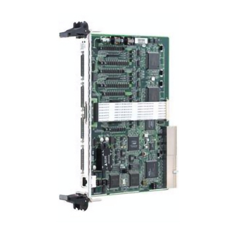
Page 20: Cpci-8168 Outline Drawing
2.2 cPCI-8168 Outline Drawing Figure 2-1: PCB Layout of the CPCI-8168 CN1: High Speed Link RJ45 Connector CN2: External Power Input Connector (+24V) CN3: SCSI 68Pin Connector for Axis0 &1 CN4: SCSI 68Pin Connector for Axis2 &3 CN5: SCSI 68Pin Connector for Axis4 &5 CN6: SCSI 68Pin Connector for Axis6 &7... -
Page 21: Cpci-8168 Hardware Installation
PCI cards in the system. 2.3.2 PCI slot selection Your computer system may have both PCI and ISA slots. Do not force the PCI card into a PC/AT slot. The cPCI-8168 can be used in any PCI slot. 2.3.3 Installation Procedures 1. - Page 22 Check the control panel of the Windows system if the card is listed by the system. If not, check the PCI settings in the BIOS or use another PCI slot. Installation...
-
Page 23: Software Driver Installation
2.4 Software Driver Installation cPCI-8168: 1. Autorun the ADLINK All-In-One CD. Choose Driver Installation -> Motion Control -> cPCI-8168 2. Follow the procedures of the installer. 3. After setup installation is completed, restart windows. Suggestion: Please download the latest software from ADLINK website if necessary. -
Page 24: Cn2 Pin Assignments: External Power Input
(AWG28 to AWG22) Naked wire length:10 mm standard The following diagram shows the external power supply system of the cPCI-8168. The external +24V power must be provided, an on- board regulator generates +5V for both internal and external usage. Installation... -
Page 25: Cn3 Pin Assignments: Scsi 68 Pins Connector
2.6 CN3 Pin Assignments: SCSI 68 Pins Connector Axis 1 - 2 Name Function Axis (1) Name Function Axis (2) EX+5V +5V power supply output EX+5V +5V power supply output EXGND Ext. power ground EXGND Ext. power ground OUT1+ Pulse signal (+),(1) OUT2+ Pulse signal (+),(2) OUT1-... -
Page 26: Cn4 Pin Assignments: Scsi 68 Pins Connector
2.7 CN4 Pin Assignments: SCSI 68 Pins Connector Axis 3 - 4 Name Function Axis (3) Name Function Axis (4) EX+5V +5V power supply output EX+5V +5V power supply output EXGND Ext. power ground EXGND Ext. power ground OUT3+ Pulse signal (+),(3) OUT4+ Pulse signal (+),(4) OUT3-... -
Page 27: Cn5 Pin Assignments: Scsi 68 Pins Connector
2.7.1 CN5 Pin Assignments: SCSI 68 Pins Connector Axis 5 - 6 Name Function Axis (5) Name Function Axis (6) EX+5V +5V power supply output EX+5V +5V power supply output EXGND Ext. power ground EXGND Ext. power ground OUT5+ Pulse signal (+),(5) OUT6+ Pulse signal (+),(6) OUT5-... -
Page 28: Cn6 Pin Assignments: Scsi 68 Pins Connector
2.8 CN6 Pin Assignments: SCSI 68 Pins Connector Axis 7 - 8 Name Function Axis (7) Name Function Axis (8) EX+5V +5V power supply output EX+5V +5V power supply output EXGND Ext. power ground EXGND Ext. power ground OUT7+ Pulse signal (+),(7) OUT8+ Pulse signal (+),(8) OUT7-... -
Page 29: Overview Of Cn3-Cn6
2.9 Overview of CN3-CN6 Installation... -
Page 30: Cn1: Rj45 Connector For Hsl
2.10 CN1: RJ45 Connector for HSL RJ45 Connector (front) Signal Function HSL2_R+ 2nd master receive data (+) HSL2_T- 2nd master transmit data (-) HSL1_R+ 1st master receive data (+) HSL1_T- 1st master transmit data (-) HSL1_T+ 1st master transmit data (+) HSL1_R- 1st master receive data (-) HSL2_T+ 2nd master transmit data (+) -
Page 31: Switch Setting
2.11 Switch Setting Installation... - Page 32 The switch bits of S1 and S2 are used to set the EL limit switch’s type. The default setting of EL switch type is “normal open” type limit switch (or “A” contact type). The switch on is to use the “nor- mal closed”...
-
Page 33: Signal Connections
Signal Connections Signal connections of all I/O’s are described in this chapter. Refer to the contents of this chapter before wiring any cable between the cPCI-8168 and any motor driver. This chapter contains the following sections: Section 3.1 Pulse Output Signals OUT and DIR Section 3.2... -
Page 34: Pulse Output Signals Out And Dir
3.1 Pulse Output Signals OUT and DIR There are 8-axis pulse output signals on cPCI-8168. For every axis, two pairs of OUT and DIR signals are used to send the pulse train and to indicate the direction. The OUT and DIR signals can also be programmed as CW and CCW signals pair. -
Page 35: Encoder Feedback Signals Ea, Eb And Ez
(2) open collector output. 3.2.1 Connection to Line Driver Output To drive the cPCI-8168 encoder input, the driver output must pro- vide at least 3.5V across the differential pairs with at least 6 mA driving capability. The ground level of the two sides must be tight together. -
Page 36: Connection To Open Collector Output
The connection between cPCI-8168, encoder, and the power sup- ply is shown in the following diagram. Please note that the exter- nal current limit resistor R is necessary to protect the cPCI-8168 input circuit. The following table lists the suggested resistor value according to the encoder power supply. -
Page 37: Origin Signal Org
3.3 Origin Signal ORG The origin signals (ORG1~ORG8) are used as input signals for origin of the mechanism. The input circuits of the ORG signals are shown as following. Usu- ally, a limit switch is used to indicate the origin of one axis. The specifications of the limit switches should with contact capacity of +24V, 6mA minimum. -
Page 38: End-Limit Signals Pel And Mel
+24V, 6mA minimum. You can use either A-type (nor- mal open) contact switch or B-type (normal closed) contact switch by setting the DIP switch S1. The cPCI-8168 is delivered with all bits of S1 set to OFF, refer to section 1.7. -
Page 39: In-Position Signal Inp
3.5 In-position Signal INP The in-position signals INP from the servo motor driver indicates the deviation error is zero, that is the servo position error is zero. The relative signal name, pin number and axis number are shown in the following table. The input circuit of the INP signals are shown in the following dia- gram. -
Page 40: Alarm Signal Alm
3.6 Alarm Signal ALM The alarm signal ALM is used to indicate the alarm status from the servo driver. The relative signal name, pin number and axis num- ber are shown in the following table. The input circuit of alarm circuit is shown in the following diagram. The ALM signals are usually from servomotor drivers, which usu- ally provide open collector output signals. -
Page 41: Deviation Counter Clear Signal Erc
3.7 Deviation Counter Clear Signal ERC The deviation counter clear signal (ERC) is active in the following 4 situations: 1. home return is complete; 2. the end-limit switch is active; 3. an alarm signal stops OUT and DIR signals; 4. an emergency stop command is issued by software (operator). -
Page 42: General-Purpose Signal Svon
3.8 General-purpose Signal SVON The SVON signals can be used as servomotor-on control or gen- eral-purpose output signals. The output circuit of SVON signal is shown in the following diagram. Signal Connections... -
Page 43: General-Purpose Signal Rdy
3.9 General-purpose Signal RDY The RDY signals can be used as motor driver ready input or gen- eral-purpose input signals. The input circuit of RDY signal is shown in the following diagram. Signal Connections... -
Page 44: Isolated Digital Output Dox
3.10 Isolated Digital Output DOx The connection of isolated-digital output is shown in the following diagram. When the isolated digital output goes to high, the sink current will be from external DOUT supplied voltage. Each transis- tor on TD62083 is OFF when reset. Spec. -
Page 45: Isolated Digital Input Dix
The Input voltage range from 5V to 24V and input resister is 4.7K (1/2W). The connection between outside signal is shown below. Maximum forward current through the diode of photocoupler is +/- 50mA. Photocoupler Isolation 4.7K ohm 1/2W DI COM+ Switch Inside cPCI-8168 DGND EXGND Signal Connections... -
Page 46: High Speed High Current Digital Output Hsout
HSOUT supplied voltage. The time delay from HSDOx to HSOUT is within 15ns. Maximum current output ability is limited by the wire of cPCI-8168 to be 1 ampere. Each transistor on IRF7303 is OFF when reset. HO_ COM... -
Page 47: High Speed Digital Input Hsin
3.13 High Speed Digital Input HSIN There are 4 channels high speed digital inputs on cPCI-8168. They are available on CN3 and CN4. Connections of these inputs are shown in the following diagram. The isolated digital input is open collector transistor structure. The Input voltage is 5V. The connection between outside signal is shown bellow. -
Page 48: Comparison Output Cmp1 And Cmp2
3.14 Comparison Output CMP1 and CMP2 The cPCI-8168 provides two pins for position compare trigger out- put. The pulse width of this trigger is 100 micro seconds for most industrial CCD camera. The pin assignment and wiring are as fol-... -
Page 49: Operation Theory
Operation Theory This chapter describes the detail operation of the motion controller card. Contents of the following sections are as follows: Section 4.1: Classifications of Motion Controller Section 4.2: Motion Control Modes Section 4.3: Motor Driver Interface Section 4.4: Mechanical Switch Interface Section 4.5: The Counters Section 4.6:... -
Page 50: Pulse Type Motion Control Interface
4.1.2 Pulse type motion control Interface The second interface of motion and motor control is pulse train type. The counts of pulses show how many steps a motor rotates and the frequency of pulses show how fast a motor runs. The time duration of frequency changes represents the acceleration rate of a motor. -
Page 51: Software Real-Time Motion Control Kernel
4.1.4 Software real-time motion control kernel There are three ways to accomplish motion control kernel: DSP- based, ASIC based, and software real-time based. A motion control system needs an absolute real-time control cycle and the calculation on the controller must provide control data at the same cycle. -
Page 52: Compare Table Of All Motion Control Types
** DSP or software realtime OS is needed 4.1.8 cPCI-8168’s motion controller type The cPCI-8168 is an ASIC based, pulse type motion controller maked into three blocks: motion ASIC, PCI card, software motion library. Users can access motion ASIC via our software motion libray under Windows 2000/XP, Linux, and RTX driver. -
Page 53: Motion Control Modes
desired speed profile, thus making it is much easier for program- mers, and mechnical or electrical engineers to discover the source of a problem. 4.2 Motion Control Modes Unlike motor control which is only for positive or negative moving, motion control make the motors run according to a specific speed profile, path trajectory and synchronous condition with other axes. -
Page 54: Absolute And Relative Position Move
Occasionally, users will need to install a linear scale or an external encoder to check the machine’s position. If the resolution of an external encoder is 10,000 pulses per 1mm and the motor will move 1mm if the motion controller sends 1,000 pulses, then if we want to move 1 mm, we need to send 1,000 pulses to the motor driver in order to get the encoder feedback value of 10,000 pulses. -
Page 55: Trapezoidal Speed Profile
4.2.3 Trapezoidal speed profile Trapezodial speed profile means the acceleration/deceleration area follows a 1st order linear velocity profile (constant accelera- tion rate). The profile chart is shown as below: The area of the velocity profile represents the distance of this motion. - Page 56 these areas. Once maximum velocity is met, there is a line con- necting the acceleration s-curve and the deceleration s-cure, dem- onstrating the maintained maximum velocity over time. This graph is called a “Bell” curve. This speed profile improves the speed of acceleration and also reduces the vibration of acceleration.
-
Page 57: Velocity Mode
If VSacc or VSdec=0, it means acceleration or deceleration use pure S-curve without linear part. The Acceleration chart of bell curve is shown below: The S-curve profile motion functions are designed to always pro- duce smooth motion. If the time for acceleration parameters com- bined with the final position don’t allow an axis to reach the maximum velocity (i.e. -
Page 58: One Axis Position Mode
The unit of distance or position is pulsed internally on the motion controller. The minimum length of distance is one pulse. Provided with the cPCI-8168 is a floating point function for users to transform a physical length to pulses. Inside our software library, we will keep the distance less than one pulse in register and apply it to the next motion function. -
Page 59: Two Axes Linear Interpolation Position Mode
4.2.7 Two axes linear interpolation position mode “Interpolation between multi-axes” means these axes start simul- taneously, and reach their ending points at the same time. Linear means the ratio of speed of every axis is a constant value. Assume that we run a motion from (0,0) to (10,4). The linear inter- polation results are shown below. -
Page 60: Two Axes Circular Interpolation Mode
The speed ratio along X-axis and Y-axis is (?X: ?Y), respectively, and the vector speed is: When calling 8-axis linear interpolation functions, the vector speed needs to define the start velocity, StrVel, and maximum velocity, MaxVel. 4.2.8 Two axes circular interpolation mode Circular interpolation means XY axes simultaneously start from an initial point, (0,0) and stop at an end point,(1800,600). -
Page 61: Continuous Motion
The command precision of circular interpolation is shown below. The precision range is at radius ±1/2 pulse. 4.2.9 Continuous motion Continuous motion means a series of motion commands or posi- tions can be run continuously. Users can set a new command right after a previous one without interrupting it. - Page 62 users have enough time to set a new command into the 2nd buffer before the current command is finished, the motion can run end- lessly. The following diagram shows this architechture of continu- ous motion. In addition to the position command, the speed command should be set correctly to perform a continuous speed profile.
- Page 63 The settings for when the 2nd command’s speed value is lower than the other two are displayed in the following diagram: The same concept is uses with an 8-axis continuous arc interpola- tion. User are able to set the speed matched between two com- mand’s speed setting.
-
Page 64: Home Return Mode
4.2.10 Home Return Mode Home return means searching a zero position point on the coordi- nate. Sometimes, users use a ORG, EZ or EL pin as a zero posi- tion on the coordinate. When a machine is starting up, the program needs to find a zero point. - Page 65 Home mode=0: (Turn ON ORG then reset counter ) When SD is not installed When SD is installed and SD is not latched Operation Theory...
- Page 66 Home mode=1: (Turn ON ORG twice then reset counter) Home mode=2: (Turn ORG ON then Slow down to count EZ numbers and reset counter) Operation Theory...
- Page 67 Home mode=3: (Turn ORG ON then count EZ numbers and reset counter) Home mode=4: (Turn ORG On then reverse to count EZ num- ber and reset counter) Operation Theory...
- Page 68 Home mode=5: (Turn ORG On then reverse to count EZ num- ber and reset counter, not using FA Speed) Home mode=6: (Turn EL On then reverse to leave EL and reset counter) Home mode=7: (Turn EL On then reverse to count EZ number and reset counter) Operation Theory...
- Page 69 Home mode=8: (Turn EL On then reverse to count EZ number and reset counter, not using FA Speed) Home mode=9: (Turn ORG On then reverse to zero position, an extension from mode 0) Operation Theory...
- Page 70 Home mode=10: (Turn ORG On then counter EZ and reverse to zero position, an extension from mode 3) Home mode=11: (Turn ORG On then reverse to counter EZ and reverse to zero position, an extension from mode 5) Operation Theory...
-
Page 71: Home Search Function
Home mode=12: (Turn EL On then reverse to count EZ num- ber and reverse to zero position, an extension from mode 8) 4.2.11 Home Search Function This mode is used to add auto searching function on normal home return mode described in the previous section no matter which position the axis is. -
Page 72: Manual Pulser Function
4.2.12 Manual Pulser Function A manual pulser is a device to generate pulse trains by hand. The pulses are sent to the motion controller and re-directed to pulse output pins. The input pulses can be multiplied or divided before sending out. The motion controller receives two kinds of pulse trains from a manual pulser device: CW/CCW and AB phase. -
Page 73: Speed Override Function
4.2.14 Speed Override Function Speed override means that users can change a command’s speed during the operation of motion. The changed parameter is a per- centage of the speed originally defined. Users can define a 100% speed value then change the speed by a percentage of the origi- nal speed while the machine is still in motion. -
Page 74: The Motor Driver Interface
Notice that if the new target’s position’s relative pulses are smaller than the original slow down pulses, this function can’t work prop- erly. 4.3 The motor driver interface We provide several dedicated I/Os which can be connected to the motor driver directly and have their own functions. Motor drivers have many kinds of I/O pins for an external motion controller to use. - Page 75 same as motor driver. The modes vs. signal type of OUT and DIR pins are listed in the table below: Mode Output of OUT pin Output of DIR pin Dual pulse output Pulse signal in plus Pulse signal in minus (CW/CCW) (or CW) direction (or CCW) direction...
-
Page 76: Pulse Feedback Input Interface
4.3.2 Pulse feedback input interface The cPCI-8168 provides one a position counter, a 28-bit up/down counter on each axis for pulse feedback counting. The position counter counts pulses from the EA and EB signals, which have plus and minus pins on the connector for differential signal inputs. - Page 77 For example, if a rotary encoder has 2000 pulses per rotation, then the counter value read from the position counter will be 8000 pulses per rotation when the AB phase is multiplied by four. If users don’t use an encoder for motion controller, the feedback source for this counter must be set as a pulse command output or the counter value will always be zero.
-
Page 78: In Position Signal
The following diagram shows the waveform. The index input (EZ) signal is the zero reference in a linear or rotary encoder. The EZ can be used to define the mechanical zero position of the mechanism. The signal logic must also be set cor- rectly in order to get a correct result. -
Page 79: Servo Alarm Signal
4.3.4 Servo alarm signal The alarm signal is an output signal from the motor driver. It tells the motion controller that there is an error inside the servo motor or driver. Once the motion controller receives this signal, the pulse commands will stop sending and the ALM signal will be ON. -
Page 80: Servo Ready Signal
There is one servo driver pin used to reset the alarm status. cPCI-8168 provides one general output pin for each axis to be used to reset servo alarm status. -
Page 81: Original Or Home Signal
4.4.1 Original or home signal cPCI-8168 provides one original or home signal per axis. This sig- nal is used for defining the axes zero position. The logic of this sig- nal must be set properly before performing a home procedure. -
Page 82: Counter Clear Switch
4.4.7 Emergency stop input cPCI-8168 has a global digital input that can stop all axes motion immediately to prevent machine damage in emergeny situations. Users can connect an emergency stop button to this input on their machine, although it is suggested that this input is kept as a nor- mal closed type for safety. -
Page 83: Command Position Counter
The cPCI-8168 is an open loop type motion controller. The motor driver receives pulses from motion controller. When the driver is not moving, we can check this command counter and see if there is an updated value. -
Page 84: Command And Feedback Error Counter
4.5.3 Command and Feedback error counter The command and feedback error counter is used to calculate the error between the command position and the feedback position. The value is calculated by subtracting the feedback position from the command position. If the ratio between command and feedback is not 1:1, the error counter is meaningless. -
Page 85: The Comparaters
4.6 The Comparaters There are 5 counter comparators of each axis: 1. Positive soft end-limit comparator to command counter 2. Negative soft end-limit comparator to command counter 3. Command and feedback error counter comparator 4. General comparator for all counters 5. -
Page 86: Trigger Comparator
4.6.4 Trigger comparator The trigger comparator is much like the general comparator only with the ability to generate a trigger pulse when the condition is met. Once the condition is met, the CMP pin on the connector will output a pulse for a specific purpose, like triggering a camera to catch a picture. -
Page 87: Other Motion Functions
4.7 Other Motion Functions Described in the following sections are the many other functions included with the cPCI-8168 motion controller. 4.7.1 Backlash compensation and slip corrections The motion controller has backlash and slip correction functions. These functions output the number of command pulses in FA speed. -
Page 88: Speed Profile Calculation Function
4.7.3 Speed profile calculation function Several speed parameters must be set for motion function. Some- times parameters conflict in a speed profile. For example, if a very fast speed and a very short distance is inputed, there is no profile for these parameters. -
Page 89: Interrupt Control
PC. The parameter “intFlag” of the software function called _8168_int_control() is to enable/disable the interrupt ser- vice. There are two kinds of interrupt groups in the cPCI-8168. One is for motion control and the other is for FPGA interrupt. The major interrupt sources from FPGA are timer interrupt and DI change of state interrupt. -
Page 90: Multiple Card Operation
4.9 Multiple Card Operation The motion controller allows more than one card in one system. Since the motion controller is plug-and-play compatible, the base address and the IRQ setting of the card are automatically assigned by the PCI BIOS during system startup. Users don’t need and can’t change the resource settings. -
Page 91: Motion Creator
After installing the software driver of cPCI-8168 on Windows 95/ 98/NT/2000, the motion creator program can be found in <chosen path >/cPCI-8168/Utility. To execute it, double click it or use desk- top “Start” > “Program files” > “cPCI8168” > “Motion Creator”. -
Page 92: About Motion Creator
5.2 About Motion Creator Before Running Motion Creator for cPCI-8168, the following issues should be kept in mind. 1. MotionCreator is a software utility written by VB 5.0, and is available only for Windows with a screen resolution higher than 800x600 environment and can not run on DOS. -
Page 93: Motion Creator Form Introducing
5.3 Motion Creator Form Introducing 5.3.1Initial forms The following Figure shows the initial view after running Motion Creator. Motion Creator... -
Page 94: Operation Form
5.3.2Operation Form There are two cPCI-8168 operating forms in Motion Creator. They are “Home Move” and “Single Axis Operation”. To activate the Home Move form, click the “Home Move” button in “Main” form. To activate the Single Axis Operation form, click the “Single Axis Operation”... - Page 95 C. Position Reset Button: Sets all position counter to specified value. The related functions are: _8168_set_position(), _8168_set_command(), _8168_reset_error_counter(), _8168_reset_target_pos() D.Motion Status: display return value of _8168_motion_done function. The related function is _8168_motion_done(). E.INT Status: Event: display of event_int_status in Hex value. The related function is _8168_get_int_status().
- Page 96 Home Move: Home move configuration form will be invoked. Allows user to set home move configuration. The related function is _8168_set_home_config() H. Position: Set the absolute position for “Absolute Mode”. It is only effective when “Absolute Mode” is selected. I. Distance: Set the relative distance for “Relative Mode”. It is only effective when “Relative Mode”...
- Page 97 PPS. Move Delay: This setting is effective only when repeat mode is set “On”. It will cause cPCI-8168 to delay specified time before it continues to the next motion. M. Speed Range: Set the max speed of motion. If “Not Fix” is selected, the “Maximum Speed”...
- Page 98 The new velocity must be defined in “Maximum Velocity”. The related function is _8168_p_change(). R. Stop Button: Decelerates the cPCI-8168 to a stop. The decel- eration time is defined in “Decel. Time”. The related function is _8168_sd_stop().
- Page 99 S. Show Velocity Curve Button: Opens a window showing the velocity vs. time curve. In this curve, every 100ms a new velocity data will be added in. To close it, click this button again. To clear data, click on the curve. T.
-
Page 100: Interface I/O Configuration Form
5.3.3Interface I/O configuration form In this form user can set the configuration of EL, ORG, EZ, ERC, ALM, INP, SD, and LTC. A. ALM Logic and Response mode: Select logic and response mode of ALM signal. The related function call is _8168_set_alm(). B. - Page 101 J. Save Config: Click this button to save current configuration to 8168.ini. K. Switch Operate form (5.3.2) L. Switch to Pulse I/O and INT factor configuration form (5.3.4) M. Back: Click this button to go back to the “main” form. Motion Creator...
-
Page 102: Pulse I/O And Int Factor Configuration Form
5.3.4Pulse I/O and INT factor configuration form In this form users can set the configuration of pulse input/output, move ration, and INT factor. A. Pulse Output Mode: Select the output mode of pulse signal (OUT/ DIR). The related function call is _8168_set_pls_outmode(). B. -
Page 103: Hslink Testing Form
5.3.5HSLink testing form In this form users can test the HSLink system in cPCI-8168. “Current Select Card ID”: The total master cards will dis- play in the “Current Select Card ID” item. User can use it to specify the card ID he wants to operate. - Page 104 “Monitor”: When users press “Connect / Auto Scan” but- ton, all slave I/O modules in the “Current Select Set ID” of the “Current Select Card ID” will be displayed on the screen. Now user can press the “Monitor” button to enter the “HSL System Monitor”...
- Page 105 “Test Slave”: When user press “Connect / Auto Scan” but- ton, all slave I/O modules in the “Current Select Set ID” of the “Current Select Card ID” will display in the screen. Now user can select a slave I/O module in the screen, then press the “Test Slave”...
-
Page 106: Gpio Tsting Form
5.3.6GPIO tsting form In this form user can test the GPIO function in cPCI-8168. A. Digital output B. Digital input C. High speed digital output D. High speed digital input E. Analog output, range from –10 to +10 V F. Analog input, range from –10 to +10 V G. -
Page 107: Function Library
Function Library This chapter describes the supporting software for cPCI-8168 cards. These functions can be used to develop application pro- gram in C or Visual Basic or C++ language. If Delphi is used the programming environment, it is necessary to transform the header file,pci_8168.h, manually. -
Page 108: List Of Functions
Software initialization _8168_close Software Close _8168_get_base_addr Get base address of cPCI-8168 _8168_get_irq_channel Get the cPCI-8168 card’s IRQ number Configure cPCI-8168 cards according to configura- _8168_config_from_file tion file ie. 8168.ini, which is created by Motion Creator. _8168_get_fpga_version Get the FPGA firmware version Pulse Input/Output Configuration: Section 6.4... - Page 109 Single Axis Position Mode: Section 6.6 Function Name Description _8168_start_tr_move Begin a relative trapezoidal profile move _8168_start_ta_move Begin an absolute trapezoidal profile move _8168_start_sr_move Begin a relative S-curve profile move _8168_start_sa_move Begin an absolute S-curve profile move Set the ratio of command pulse and feedback _8168_set_move_ratio pulse.
- Page 110 Function Name Description Begin a absolute 2-axis linear interpolation for X & _8168_start_sa_move_cd Y (Z &U), (A & B), (C & D) with S-curve profile _8168_start_tr_line2 Begin a relative 2-axis linear interpolation for any 2 _8168_start_tr_line2s axes among axis 0 to 3 (s, for axis 4 to 7), with trapezoidal profile _8168_start_sr_line2 Begin a relative 2-axis linear interpolation for any 2...
- Page 111 Function Name Description Begin a relative 4-axis (axis 0 to 3; s, for axis 4 to _8168_start_sr_line4s 7) linear interpolation with S-curve profile _8168_start_ta_line4 Begin a absolute 4-axis (axis 0 to 3; s, for axis 4 to _8168_start_ta_line4s 7) linear interpolation with trapezoidal profile _8168_start_sa_line4 Begin a absolute 4-axis (axis 0 to 3;...
- Page 112 Set state of general purpose output pin _8168_set_sd Set SD logic and operating mode _8168_set_el Set EL logic and operating mode Motion I/O Monitoring: Section 6.13 Function Name Description _8168_get_io_status Get all the motion I/O status of cPCI-8168 Function Library...
- Page 113 Interrupt Control: Section 6.14 Function Name Description _8168_int_control Enable/Disable INT service _8168_int_enable Enable event (Windows only) _8168_int_disable Disable event (Windows only) _8168_int_enableA Enable bit mapped interrupt event (Windows only) _8168_int_diableA Disable bit mapped interrupt event (Windows only) Mapping bit mapped interrupt event (Windows _8168_map_axis_event only) _8168_get_int_status...
- Page 114 Position Control and Counters: Section 6.15 Function Name Description _8168_get_position Get the value of feedback position counter _8168_set_position Set the feedback position counter _8168_get_command Get the value of command position counter _8168_set_command Set the command position counter _8168_get_error_counter Get the value of position error counter _8168_reset_error_counter Reset the position error counter _8168_get_general_counter Get the value of general counter...
- Page 115 Position Compare and Latch: Section 6.16 Function Name Description _8168_set_ltc_logic Set the LTC logic _8168_get_latch_data Get latched counter data _8168_set_soft_limit Set soft limit _8168_enable_soft_limit Enable soft limit function _8168_disable_soft_limit Disable soft limit function _8168_set_error_counter_c Step-losing detection heck _8168_set_general_compar Set general-purposed comparator ator _8168_set_trigger_compara Set Trigger comparator...
- Page 116 Multiple Axes Simultaneous Operation: Section 6.18 Function Name Description _8168_set_tr_move_all _8168_set_sr_move_all Multi-axis simultaneous operation setup _8168_set_ta_move_all _8168_set_sa_move_all _8168_start_move_all Start motion simultaneously for all configured axis _8168_stop_move_all Stop motion simultaneously for all configured axis HSL Initialization: Section 6.19 Function Name Description W_HSL_Start Start HSLink communication W_HSL_Auto_Start...
- Page 117 General-purposed DIO: Section 6.22 Function Name Description _8168_d_output Digital output _8168_d_input Digital input _8168_hd_output High speed digital output _8168_hd_input High speed digital input General-purposed AIO: Section 6.23 Function Name Description _8168_read_ad Read AD value _8168_write_da Write DA value High Resolution Timer: Section 6.24 Function Name Description _8168_set_h_timer...
-
Page 118: C/C++ Programming Library
64-bit double-precision floating-point to 1.797683134862315E309 Boolean Boolean logic value TRUE, FALSE The functions of cPCI-8168’s software drivers use full-names to represent the functions’ real meaning. The naming convention rules are : In ‘C’ programming Environment: _{hardware_model}_{action_name}. e.g. _8168_Initial(). In order to recognize the difference between C library and VB library, a capital “B”... -
Page 119: Initialization
_8168_close : This function is used to close cPCI-8168 cards and release the cPCI-8168 related resources, which should be called at the end of an application. _8168_get_irq_channel: This function is used to get the cPCI-8168 card’s IRQ number. - Page 120 When this function is executed, all cPCI-8168 cards in the system will be configured as the following functions are called according to the recorded parameters in 8168.ini. _8168_set_pls_outmode _8168_set_feedback_src _8168_set_pls_iptmode _8168_set_home_config _8168_set_int_factor _8168_set_el _8168_set_ltc_logic _8168_set_erc _8168_set_sd _8168_set_alm _8168_set_inp _8168_set_move_ratio _8168_get_fpga_version: This function is for getting the FPGA firmware version number.
- Page 121 The cPCI-8168 card index number. *irq_no: Irq number of specified cPCI-8168 card. *base_addr: base address of specified cPCI-8168 card *Filename: The specified filename recording the configuration of cPCI-8168. This file must be created by MotionCreator of cPCI-8168. @ Return Code ERR_NoError...
-
Page 122: Pulse Input/Output Configuration
6.4 Pulse Input/Output Configuration @ Name _8168_set_pls_outmode – Set the configuration for pulse command output. _8168_set_pls_iptmode – Set the configuration for feedback pulse input. _8168_set_feedback_src – Enable/Disable the external feed- back pulse input @ Description _8168_set_pls_outmode: Configure the output modes of command pulse. There are more than 6 modes for command pulse output. - Page 123 Visual Basic (Windows) B_8168_set_pls_outmode (ByVal AxisNo As Integer, ByVal pls_outmode As Integer) As Integer B_8168_set_pls_iptmode (ByVal AxisNo As Integer, ByVal pls_iptmode As Integer, ByVal pls_logic As Integer) As Integer B_8168_set_feedback_src (ByVal AxisNo As Integer, ByVal Src As Integer) As Integer @ Argument AxisNo: axis number designated to configure pulse Input/Output.
- Page 124 Src: Counter source Value Meaning External Feedback Command pulse @ Return Code ERR_NoError Function Library...
-
Page 125: Velocity Mode Motion
6.5 Velocity mode motion @ Name _8168_tv_move – Accelerate an axis to a constant velocity with trapezoidal profile _8168_sv_move – Accelerate an axis to a constant velocity with S-curve profile _8168_v_change – Change speed on the fly _8168_sd_stop – Decelerate to stop _8168_emg_stop –... - Page 126 _8168_v_change is also applicable on positioning motion. Note: The velocity profile is decided by the original motion profile. When using in S-curve, set the motion to be pure S-curve. There are some limitations for this function under position motion, please refer to section 4.6.1 before using it.
- Page 127 I16 _8168_emg_stop(I16 AxisNo); F64 _8168_fix_speed_range(I16 AxisNo, F64 MaxVel); I16 _8168_unfix_speed_range(I16 AxisNo); I16 _8168_get_current_speed(I16 AxisNo, F64 *speed); Visual Basic (Windows 95/NT) B_8168_tv_move (ByVal AxisNo As Integer, ByVal StrVel As Double, ByVal MaxVel As Double, ByVal Tacc As Double) As Integer B_8168_sv_move (ByVal AxisNo As Integer, ByVal StrVel As Double, ByVal MaxVel As Double, ByVal Tacc As Double, ByVal SVacc As Double) As Integer...
- Page 128 Tdec: specified deceleration time in unit of second *Speed: Variable to save current speed. (speed range: 0~6553500) @ Return Code ERR_NoError ERR_SpeedError ERR_SpeedChangeError ERR_SlowDownPointError ERR_AxisAlreadyStop Function Library...
-
Page 129: Single Axis Position Mode
6.6 Single Axis Position Mode @ Name _8168_start_tr_move – Begin a relative trapezoidal profile move _8168_start_ta_move – Begin an absolute trapezoidal profile move _8168_start_sr_move – Begin a relative S-curve profile move _8168_start_sa_move – Begin an absolute S-curve profile move _8168_set_move_ratio –Set the ratio of command pulse and feedback pulse. - Page 130 for motion completion but immediately return control to the pro- gram. _8168_start_ta_move : This function causes the axis to accelerate from a starting velocity, slow at a constant velocity, and decelerate to a stop at the speci- fied absolute position with trapezoidal profile. The acceleration and deceleration time is specified independently.
- Page 131 SD pin may be used either as Slow-Down signal input or as Posi- tion Change Signal (PCS) input. This function is only valid for the first 4 axes of each cPCI-8168 board. Please refer to section 4.3.1 _8168_backlash_comp: Whenever direction change is occurred, The cPCI-8168 outputs backlash corrective pulses before sending commands.
- Page 132 I16 _8168_start_sa_move(I16 AxisNo, F64 Pos, F64 StrVel, F64 MaxVel, F64 Tacc, F64 Tdec, F64 SVacc, F64 SVdec); I16 _8168_set_move_ratio(I16 AxisNo, F64 move_ratio); I16 _8168_p_change(I16 AxisNo, F64 NewPos); I16 _8168_set_pcs_logic(I16 AxisNo, I16 pcs_logic); I16 _8168_set_sd_pin(I16 AxisNo, I16 Type); I16 _8168_backlash_comp(I16 AxisNo, I16 BCompPulse);...
- Page 133 B_8168_backlash_comp (ByVal AxisNo As Integer, ByVal BCompPulse As Integer, ByVal ForwardTime As Integer) As Integer B_8168_suppress_vibration (ByVal AxisNo As Integer, ByVal ReserveTime As Integer, ByVal ForwardTime As Integer) As Integer @ Argument AxisNo: axis number designated to move or change position. Dist: specified relative distance to move Pos: specified absolute position to move StrVel: starting velocity of a velocity profile in unit of pulse per...
- Page 134 @ Return Code ERR_NoError ERR_SpeedError ERR_PChangeSlowDownPointError ERR_MoveRatioError Function Library...
-
Page 135: Linear Interpolated Motion
_8168_start_tr_line2(s) – Begin a relative 2-axis linear interpolation for any 2 axes from one motion chip with trapezoidal profile. The (s) means secondary motion chip in one cPCI-8168. _8168_start_sr_line2(s) – Begin a relative 2-axis linear interpolation for any 2 axes from one motion chip with S-curve pro- file The (s) means secondary motion chip in one cPCI-8168. - Page 136 _8168_start_ta_line3(s) – Begin an absolute 3-axis linear interpolation for any 3 axes from one motion chip with trapezoidal profile. The (s) means secondary motion chip in one cPCI-8168. _8168_start_sa_line3(s) – Begin an absolute 3-axis linear interpolation for any 3 axes from one motion chip with S-curve pro- file.
- Page 137 I16 _8168_start_ta_line2(s)(I16 CardNo, I16 *AxisArray, F64 PosX, F64 PosY, F64 StrVel, F64 MaxVel, F64 Tacc, F64 Tdec); I16 _8168_start_sr_line2(s)(I16 CardNo, I16 *AxisArray, F64 DistX, F64 DistY, F64 StrVel, F64 MaxVel, F64 Tacc, F64 Tdec, F64 SVacc, F64 SVdec); I16 _8168_start_sa_line2(s)(I16 CardNo, I16 *AxisArray, F64 PosX, F64 PosY, F64 StrVel, F64 MaxVel, F64 Tacc, F64 Tdec, F64 SVacc, F64 SVdec);...
- Page 138 Double, ByVal StrVel As Double, ByVal MaxVel As Double, ByVal Tacc As Double, ByVal Tdec As Double) As Integer B_8168_start_ta_move_(MN) (ByVal CardNo As Integer, ByVal Pos As Double, ByVal Pos As Double, ByVal StrVel As Double, ByVal MaxVel As Double, ByVal Tacc As Double, ByVal Tdec As Double) As Integer B_8168_start_sr_move_(MN) (ByVal CardNo As Integer, ByVal Dist As Double, ByVal Dist As...
- Page 139 Tacc As Double, ByVal Tdec As Double, ByVal SVacc As Double, ByVal SVdec As Double) As Integer B_8168_start_tr_line3(s) (ByVal CardNo As Integer, AxisArray As Integer, ByVal DistX As Double, ByVal DistY As Double, ByVal DistZ As Double, ByVal StrVel As Double, ByVal MaxVel As Double, ByVal Tacc As Double, ByVal Tdec As Double) As Integer B_8168_start_ta_line3(s) (ByVal CardNo As...
- Page 140 As Double, ByVal DistZ As Double, ByVal DistU As Double, ByVal StrVel As Double, ByVal MaxVel As Double, ByVal Tacc As Double, ByVal Tdec As Double, ByVal SVacc As Double, ByVal SVdec As Double) As Integer B_8168_start_sa_line4(s) (ByVal CardNo As Integer, ByVal PosX As Double, ByVal PosY As Double, ByVal PosZ As Double, ByVal PosU As Double, ByVal StrVel As Double, ByVal MaxVel...
- Page 141 Note: If the function is for secondary axes (Axis 4~7), the AxisArray must have the axes indexing from the range of 4~7. @ Return Code ERR_NoError ERR_SpeedError ERR_AxisArrayError Function Library...
-
Page 142: Circular Interpolation Motion
6.8 Circular Interpolation Motion @ Name _8168_start_r_arc_xy – Begin a relative circular interpolation for X & Y on primary motion chip _8168_start_a_arc_xy – Begin a absolute circular interpola- tion for X & Y on primary motion chip _8168_start_r_arc_zu –Begin a relative circular interpolation for Z &... - Page 143 @ Description Functions Relative / Absolute Target Axes _8168_start_r_arc_xy Axis 0 & 1 _8168_start_a_arc_xy Axis 0 & 1 _8168_start_r_arc_zu Axis 2 & 3 _8168_start_a_arc_zu Axis 2 & 3 _8168_start_r_arc_ab Axis 4 & 5 _8168_start_a_arc_ab Axis 4 & 5 _8168_start_r_arc_cd Axis 6 & 7 _8168_start_a_arc_cd Axis 6 &...
- Page 144 I16 _8168_start_r_arc2(I16 CardNo, I16 *AxisArray, F64 OffsetCx, F64 OffsetCy, F64 OffsetEx, F64 OffsetEy, I16 DIR, F64 MaxVel); I16 _8168_start_a_arc2(I16 CardNo, I16 *AxisArray, F64 Cx, F64 Cy, F64 Ex, F64 Ey, I16 DIR, F64 MaxVel); I16 _8168_start_r_arc2(I16 CardNo, I16 *AxisArray, F64 OffsetCx, F64 OffsetCy, F64 OffsetEx, F64 OffsetEy, I16 DIR, F64 MaxVel);...
- Page 145 Double, ByVal OffsetCy As Double, ByVal OffsetEx As Double, ByVal OffsetEy As Double, ByVal DIR As Integer, ByVal MaxVel As Double) As Integer @ Argument CardNo: Card number designated to perform linear interpolation OffsetCx: X-axis offset to center OffsetCy: Y-axis offset to center OffsetEx: X-axis offset to end of arc OffsetEy: Y-axis offset to end of arc Cx: specified X-axis absolute position of center...
-
Page 146: Home Return Mode
6.9 Home Return Mode @ Name _8168_set_home_config – Set the configuration for home return. _8168_home_move – Perform a home return move. _8164_escape_home – Escape Home Function _8164_home_search –Auto-Search Home Switch @ Description _8168_set_home_config: Configure the home return mode, origin & index signal(EZ) logic, EZ count and ERC output options for home_move() function. - Page 147 @ Syntax C/C++ (DOS, Windows) I16 _8168_set_home_config(I16 AxisNo, I16 home_mode, I16 org_logic, I16 ez_logic, I16 ez_count, I16 erc_out); I16 _8168_home_move(I16 AxisNo, F64 StrVel, F64 MaxVel, F64 Tacc); I16 _8164_escape_home(I16 AxisNo, F64 SrVel,F64 MaxVel,F64 Tacc); I16 _8164_home_search(I16 AxisNo, F64 StrVel, F64 MaxVel, F64 Tacc, F64 ORGOffset);...
- Page 148 EZ_logic=0, active low; EZ_logic=1, active high. ez_count: 0~15 (Please refer to section 4.1.8) erc_out: Set ERC output options. erc_out =0, no erc out; erc_out =1, erc out when homing finish StrVel: starting velocity of a velocity profile in unit of pulse per second MaxVel: starting velocity of a velocity profile in unit of pulse per second...
-
Page 149: Manual Pulser Motion
6.10 Manual Pulser Motion @ Name _8168_set_pulser_iptmode - set the input signal modes of pulser _8168_pulser_vmove – manual pulser v_move _8168_pulser_pmove – manual pulser p_moce _8168_pulser_home_move – manual pulser home move _8164_set_pulser_ratio – Set manual pulser ratio for actual output pulse rate _8164_pulser_r_line2 –... - Page 150 upon receiving one pulse from the pulser, until the sd_stop or emg_stop command is written or the home move finish. _8164_set_pulser_ratio: Set manual pulse ratio for actual output pulse rate. The formula for manual pulse output rate is: Output Pulse Count = Input Pulse Count x 4 x (MultiF+1) x (DivF+1)/2048 The DivF=0~2047 Divide Factor The MultiF=0~31 Multiplication Factor...
- Page 151 I16 _8168_pulser_r_line2(I16 CardNo,I16 *AxisArray, F64 DistX, F64 DistY, F64 SpeedLimit); I16 _8168_pulser_r_arc2(I16 CardNo, I16 *AxisArray, F64 OffsetCx, F64 OffsetCy, F64 OffsetEx, F64 OffsetEy, I16 DIR, F64 MaxVel); I16 _8168_pulser_r_line2s(I16 CardNo,I16 *AxisArray, F64 DistX, F64 DistY, F64 SpeedLimit); I16 _8168_pulser_r_arc2s(I16 CardNo, I16 *AxisArray, F64 OffsetCx, F64 OffsetCy, F64 OffsetEx, F64 OffsetEy, I16 DIR, F64 MaxVel);...
- Page 152 ByVal DistY As Double, ByVal SpeedLimit As Double) As Integer B_8164_pulser_r_arc2s(ByVal CardNo As Integer, AxisArray As Integer, ByVal OffsetCx As Double, ByVal OffsetCy As Double, ByVal OffsetEx As Double, ByVal OffsetEy As Double, ByVal DIR As Integer, ByVal MaxVel As Double) As Integer @ Argument AxisNo: axis number designated to start manual move InputMode: setting of manual pulser input mode from PA and PB...
- Page 153 DistY: specified relative distance of second axis to move OffsetCx: X-axis offset from center OffsetCy: Y-axis offset from center OffsetEx: X-axis offset from the end of arc OffsetEy: Y-axis offset from the end of arc DIR: Specified direction of arc, CW:0 , CCW:1 SpeedLimit: Maximum tangential velocity in units of pulse per second MaxVel: Maximum tangential velocity in units of pulse per second...
-
Page 154: Motion Status
6.11 Motion Status @ Name _8168_motion_done – Return the motion status @ Description _8168_motion_done: Return the motion status of cPCI-8168. @ Syntax C/C++ (DOS, Windows) I16 _8168_motion_done(I16 AxisNo); Visual Basic (Windows) B_8168_motion_done (ByVal AxisNo As Integer) As Integer @ Argument... - Page 155 12 At FH speed ( maximum velocity ) 13 In deceleration 14 Waiting for INP signal 15 Reserved Function Library...
-
Page 156: Motion Interface I/O
6.12 Motion Interface I/O @ Name _8168_set_alm – Set alarm logic and operating mode _8168_set_el– Set EL logic and operating mode _8168_set_inp– Set Inp logic and operating mode _8168_set_erc– Set ERC logic and timing _8168_set_servo – Set state of general purpose output pin _8168_set_sd –... - Page 157 @ Syntax C/C++ (DOS, Windows) I16 _8168_set_alm(I16 AxisNo, I16 alm_logic, I16 alm_mode); I16 _8168_set_el(I16 AxisNo, I16 el_mode); I16 _8168_set_inp(I16 AxisNo, I16 inp_enable, I16 inp_logic); I16 _8168_set_erc(I16 AxisNo, I16 erc_logic, I16 erc_on_time); I16 _8168_set_servo(I16 AxisNo, I16 on_off); I16 _8168_set_sd(I16 AxisNo, I16 enable, I16 sd_logic, I16 sd_latch, I16 sd_mode);...
- Page 158 alm_mode=0, motor immediately stops(Default) alm_mode=1, motor decelerates then stops. el_mode: reacting modes when receiving EL signal. el_mode=0, motor immediately stops.(Default) el_mode=1, motor decelerates then stops. inp_enable: INP function enable/disable inp_enable=0, Disabled (Default) inp_enable=1, Enabled inp_logic: setting of active logic for INP signal inp_logic=0, active LOW.
- Page 159 sd_logic: setting of active logic for INP signal sd_logic=0, active LOW. sd_logic=1, active HIGH. sd_latch: setting of latch control for SD signal sd_latch=0, do not latch. sd_latch=1, latch. sd_mode: setting the reacting mode of SD signal sd_mode=0, slow down only sd_mode=1, slow down then stop @ Return Code ERR_NoError...
-
Page 160: Motion I/O Monitoring
6.13 Motion I/O Monitoring @ Name _8168_get_io_status –Get all the motion I/O status of cPCI- 8168 @ Description _8168_get_io_status: Get all the I/O status for each axis. The definition for each bit is as follows: Name Description RDY pin input Alarm Signal Positive Limit Switch Negative Limit Switch... - Page 161 Visual Basic (Windows) B_8168_get_io_status (ByVal AxisNo As Integer, io_sts As Integer) As Integer @ Argument AxisNo: axis number for I/O control and monitoring *io_status: I/O status word. Where “1’ is ON and “0” is OFF. ON/OFF state is read based on the corresponding set logic. @ Return Code ERR_NoError Function Library...
-
Page 162: Interrupt Control
6.14 Interrupt Control @ Name _8168_int_control – Enable/Disable INT service _8168_set_int_factor – Set INT factor For Windows: _8168_int_enable – Enable event _8168_int_disable – Disable event _8168_get_int_status – Get INT Status _8168_link_interrupt – Set link to interrupt call back function _8168_int_enableA – Enable bit axis event _8168_int_disableA –... - Page 163 The following talbe contains the definitions of event type interrupt factors. By setting the rela- tive bit as 1, cPCI-8168 can generate interrupt signal to host PC when the condition of bit is met.
- Page 164 CSTA input is ON 19~3 (Reserved) For Windows: _8168_int_enable : This function is used to pass a Windows event array for one card. The size of this array is 8, one-dimension. Each index indicates one axis. _8168_int_disable: This function is used to close the Windows event array passed to _8168_int_enable().
- Page 165 One axis is stopped from the other axis’s error stop Pulser input buffer overflow and stop Interpolation counter overflow Encoder input signal error (axis does not stop) Pulser input signal error (axis does not stop) 18~31 Always 0 The second one is for event interrupt status which can be masked definitions _8168_set_int_factor().
- Page 166 _8168_link_interrupt: This function is used to link interrupt call back function. Don’t place too many codes inside the call back function. We suggest useing Windows event to handle interrupt _8168_int_enableA: This function is used to pass a interrupt factor mapping event arrays for each axis.
- Page 167 _8168_get_event_int: This function is used to get event_int_status. _8168_get_error_int: This function is used to get error_int_status. _8168_get_irq_status: This function allows user to confirm if the designated card gener- ates the INT signal to host PC. _8168_not_my_irq: This function must be called after knowing not the designated card generates the INT signal to host PC.
- Page 168 void interrupt _8168_isr8 (void); void interrupt _8168_isr9 (void); void interrupt _8168_isra (void); void interrupt _8168_isrb (void); C/C++ (Windows) I16 _8168_int_control(U16 cardNo, U16 intFlag ); I16 _8168_set_int_factor(I16 AxisNo, U32 int_factor ); I16 _8168_int_enable(I16 CardNo, HANDLE *phEvent); I16 _8168_int_disable(I16 CardNo); I16 _8168_get_int_status(I16 AxisNo, U32 *error_int_status, U32 *event_int_status );...
- Page 169 B_8168_map_axis_event(ByVal AxisNo As Integer, ByVal EventNo As Integer, ByVal EventIntfactor As Long) As Integer @ Argument cardNo: card number 0,1,2,3… AxisNo: axis number 0,1,2,3,4… intFlag: int flag, 0 or 1 (0: Disable, 1:Enable) int_factor: interrupt factor, refer to previous table *int_type: DOS only, Interrupt type, (1: error int, 2: event int, 3: both happened ) *event_int: event_int_status, , refer to event_int_status table...
-
Page 170: Position Control And Counters
If move ratio is 0.5, than the value read will be twice as much as the counter value. The source of feedback counter is selectable by function _8168_set_feedback_src() to be external EA/EB or pulse output of cPCI-8168. _8168_set_position(): Function Library... - Page 171 (By default, the source is pulser input.) _8168_get_target_pos(): This function is used to read the value of target position recorder. The target position recorder is maintained by cPCI-8168 software driver. It records the position to settle down for current running motion. _8168_reset_target_pos(): This function is used to set new values for the target position recorder.
- Page 172 _8168_get_rest_command(): This function is used to read remaining pulse counts until the cur- rent motion is finished. _8168_check_rdp(): This function is used to read the ramping down point data. The ramping down point is the position where deceleration starts. The data is stored as pulse count, and it causes the axis start to decel- erate when remaining pulse counts reach the data.
- Page 173 B_8168_get_error_counter (ByVal AxisNo As Integer, error_counter As Integer) As Integer B_8168_reset_error_counter (ByVal AxisNo As Integer) As Integer B_8168_get_general_counter (ByVal AxisNo As Integer, CntValue As Double) As Integer B_8168_set_general_counter (ByVal AxisNo As Integer, ByVal CntSrc As Integer, ByVal CntValue As Double) As Integer B_8168_get_target_pos (ByVal AxisNo As Integer, Pos As Double) As Integer B_8168_reset_target_pos (ByVal AxisNo As Integer,...
- Page 174 range: 0~167777215 CntSrc: Source of general counter 0 : Command pulses 1: EA/EB 2: PA/PB (Default) 3: CLK/2 @ Return Code ERR_NoError ERR_PosOutofRange Function Library...
-
Page 175: Position Compare And Latch
_8168_build_compare_table – Build compare data via com- pare table _8168_cmp_v_change – Speed change by comparator @ Description _8168_set_ltc_logic(): This function is used to set the logic of latch input. This function is applicable only for the last two axes in every cPCI-8168 card. Function Library... - Page 176 Once enabled, the action of soft limit will be exactly the same as the physical limit. _8168_set_error_counter_check(): This function is used to enable the step losing checking facility. By giving a tolerance value, the cPCI-8168 will generate an interrupt (event_int_status , bit 10) when position error counter exceeds tol- erance. _8168_set_general_comparator(): This function is used to set the source and comparing value for general comparator.
- Page 177 _8168_check_compare_data(): This function is used to obtain current comparing data of desig- nated comparator. _8168_check_compare_status(): This function is used to obtain the status of all comparators. When some comparators come into existence, the relative bit of cmp_sts will become ‘1’, otherwise ‘0’. Notice that the status will not be latched after compare condition is true.
- Page 178 _8168_set_general_comparator() must be set to ‘3’. The compare data also _8168_set_general_comparator(). The remain distance, the compare point’s velocity , the new velocity and the acceleration time are set by _8168_cmp_v_change(). @ Syntax C/C++ (DOS, Windows) I16 _8168_set_ltc_logic(I16 AxisNo_2or3, I16 ltc_logic); I16 _8168_get_latch_data(I16 AxisNo, I16 Counter, F64 *Pos);...
- Page 179 B_8168_get_latch_data (ByVal AxisNo As Integer, ByVal Counter As Integer, Pos As Double) As Integer B_8168_set_soft_limit (ByVal AxisNo As Integer, ByVal PLimit As Long, ByVal NLimit As Long) As Integer B_8168_disable_soft_limit (ByVal AxisNo As Integer) As Integer B_8168_enable_soft_limit (ByVal AxisNo As Integer, ByVal Action As Integer) As Integer B_8168_set_error_counter_check (ByVal AxisNo As Integer, ByVal Tolerance As Integer, ByVal...
- Page 180 AxisNo: Axis number Counter: Specified Counter Counter = 0 , Command counter Counter = 1 , Feedback counter Counter = 2 , Error Counter Counter = 3 , General Counter Pos: Latched counter value, PLimit: Soft limit value in positive direction NLimit: Soft limit value in negative direction Action: The reacting method of soft limit Action =0, INT only...
- Page 181 CmpMethod =4, CmpValue>Counter CmpMethod =5, CmpValue<Counter CmpAction: The reacting mode when comparison comes into exist CmpAction =0, INT only CmpAction =1, Immediately stop CmpAction =2, slow down then stop CmpAction =3, speed change Data: Comparing value, cmp_sts: status of comparator Meaning 0 +Softlimit On 1 -SoftLimit On...
- Page 182 oldvel: The velocity at compare point. User must specify it man- ually. newvel: The new velocity. AccTime: The acceleration time. @ Return Code ERR_NoError ERR_CompareNoError ERR_CompareMethodError ERR_CompareAxisError ERR_CompareTableSizeError ERR_CompareFunctionError ERR_CompareTableNotReady ERR_CompareLineNotReady ERR_HardwareCompareAxisWrong ERR_AutocompareSourceWrong ERR_CompareDeviceTypeError Function Library...
-
Page 183: Continuous Motion
6.17 Continuous motion @ Name _8168_set_continuous_move – Enable continuous motion _8168_check_continuous_buffer – check if the buffer is empty @ Description _8168_set_continuous_move(): This function is necessary before and after continuous motion. _8168_check_continuous_buffer(): This function is used to detect if the command buffer is empty or not. - Page 184 @ Return Value ERR_NoError Return value of _8168_check_continuous_buffer(): 0: Continuous buffer is not full 1: Continuous buffer is full Function Library...
-
Page 185: Multiple Axes Simultaneous Operation
6.18 Multiple Axes Simultaneous Operation @ Name _8168_set_tr_move_all – Multi-axis TR mode simultaneous operation setup. _8168_set_sr_move_all – Multi-axis SR mode simultaneous operation setup. _8168_set_ta_move_all – Multi-axis TA mode simultaneous operation setup. _8168_set_sa_move_all – Multi-axis SA mode simultaneous operation setup. _8168_start_move_all – Start motion simultaneously for all configured axis _8168_stop_move_all –... - Page 186 int main() axes[2] = {0, 4}; dist[2] = {8000.0, 12000.0}, str_vel[2]={0.0, 0.0}, max_vel[2]={4000.0, 6000.0}, Tacc[2]={0.04, 0.06}, Tdec[2]= {0.04, 0.06}; _8168_set_tr_move_all(2, axes, dist, str_vel, max_vel, Tacc, Tdec); _8168_start_move_all(axes[0]); returnERR_NoError; @ Syntax C/C++ (DOS, Windows) I16 _8168_set_tr_move_all(I16 TotalAxes, I16 *AxisArray, F64 *DistA, F64 *StrVelA, F64 *MaxVelA, F64 *TaccA, F64 *TdecA);...
- Page 187 B_8168_set_sr_move_all(ByVal TotalAxes As Integer, AxisArray As Integer, DistA As Double, StrVelA As double, MaxVelA As double, TaccA As double, TdecA As double, SvaccA As double, SvdecA As double); B_8168_set_ta_move_all(ByVal TotalAxes As Integer, AxisArray As Integer, PosA As Double, StrVelA As double, MaxVelA As double, TaccA As double, TdecA As double);...
-
Page 188: Hsl Initialization
6.19 HSL Initialization @ Name W_HSL_Start – Start HSLink communication with specified max- imum salve ID W_HSL_Auto_Start – Start HSLink communication by automati- cally detecting maximum salve ID W_HSL_Stop –Stop HSLink communication @ Description W_HSL_Start(): This function is used to set the maximum ID of connected slave I/ O module and start to scan these slave I/O modules. - Page 189 @ Argument card_ID: Designated card number set_ID: 0 for the first HSLink master IC, 1 for the second. sat_num: The maximum slave ID connect to the HSL master card by the @ Return Value ERR_NoError ERR_ConnectIndex ERR_InvalidBoardNumber Function Library...
-
Page 190: Hsl Connection Information
6.20 HSL Connection Information @ Name W_HSL_Connect_Status – Get slave module's status W_HSL_Slave_Live –Check if the slave alive @ Description W_HSL_Connect_Status(): This function is to read the communication status of specified slave I/O module. W_HSL_Slave_Live(): This function is to get status of specified slave I/O module (live or die). - Page 191 Bit 0 is Data_Req bit. Bit 2 is for CHK1. (If Bit2 is 1. It mean that there is 1 time com- munication error). Bit 3 is for CHK3. (If Bit3 is 1. It mean that there are 3 times communication error).
-
Page 192: Hsl Dio Read/Write
6.21 HSL DIO Read/Write @ Name W_HSL_DIO_In – Digital input from all bits in one slave module W_HSL_DIO_Channel_In – Digital input from one bit W_HSL_DIO_Out – Digital output for all bits in one slave module W_HSL_DIO_Channel_Out – Digital output for one bit W_HSL_DIO_Memory_Out –... - Page 193 W_HSL_DIO_Memory_In(): This function is used to read the digital input values from all slave I/O modules which the set value is set_ID and card no is card_ID.In this function, user can read all digital input values from all slave I/O modules at one time. @ Syntax C/C++ (DOS, Windows) I16 W_HSL_DIO_In(I16 card_ID, I16 set_ID, I16...
- Page 194 W_HSL_DIO_Memory_In (ByVal card_ID As Integer, ByVal set_ID As Integer, Buffer As Any) As Integer @ Argument card_ID: Designated card number set_ID: 0 for the first HSLink master IC, 1 for the second. slave_No: Specified slave I/O module. in_data: the digital input data of this slave I/O module. In this value.
-
Page 195: General-Purposed Dio
6.22 General-purposed DIO @ Name _8168_d_output – Digital output _8168_d_input – Digital input _8168_hd_output – High speed digital output _8168_hd_input – High speed digital input @ Description _8168_d_output(): Set the on_off status for general-purposed digital output pin. _8168_d_input(): Read status of general-purposed digital input pin. _8168_hd_output(): Set the on_off status for general-purposed high speed DO pin. - Page 196 @ Argument AxisNo: Designated axis number Value: On-Off Value for output Value =0, output OFF Value =1, output ON @ Return Value ERR_NoError Function Library...
-
Page 197: General-Purposed Aio
6.23 General-purposed AIO @ Name _8168_read_ad – Read AD value _8168_write_da – Write DA value @ Description _8168_read_ad(): Read value for specified AD channel _8168_write_da(): Write value into specified DA channel @ Syntax C/C++ (DOS, Windows) F64 _8168_read_ad(I16 CardNo, I16 ch); I16 _8168_write_da(I16 CardNo ,I16 ch, F64 v);... -
Page 198: High Resolution Timer Functions
6.24 High Resolution Timer Functions @ Name _8168_set_h_timer – Start high resolustion timer counter _8168_h_timer – Get high resolution timer counter value _8168_ssleep – Sleep according to a high resolution timer _8168_delay_time – Delay for a while _8168_delay_time_mt – Delay for a while within thread @ Description _8168_set_h_timer: This function is used for starting a high resolution timer on cPCI-... - Page 199 duration equal to the function’s delay time parameter. The mini- mum delay time is 0.1ms. _8168_delay_time_mt: This function is used to pause the program for a specific amount of time. It will not consume CPU time under Windows by using WaitForSingleObject().
- Page 200 @ Argument CardNo: Card number designated T_base_Mulx: The counter value for timer counter and interrupt. The counter base clock is fixed to 40ns. Suggested timer counter is more than 100us so the minimum value for suggestion is 2500 Enable: 1 for enable and 0 for disable timer_no: 0~63 sleep_time_mulx: according to set_h_timer() base.
-
Page 201: Di Change Of State
6.25 DI Change of state @ Name _8168_set_d_cos – Enable DI pin change of state function _8168_wait_d_cos – Wait DI pin change of state event _8168_set_hd_cos – Enable HDI pin change of state function _8168_wait_hd_cos – Wait HDI pin change of state event _8168_get_cos_status –... - Page 202 time out time must be set more than 10ms to prevent the inaccur- ancy of Windows timer. _8168_get_cos_status: This function is used for getting the change of state status in one card. Calling the status will clear the current status. It is not sug- gested that this function is used during interrupt for COS functions.
- Page 203 Cos_status: return by _8168_get_cos_status() Bit0~7 for DI0~7 change of state status, 1 for happened. Bit8~11 for HDI0~3 change of status status 1 for happened Bit15 is for change of state status when any bit has COS hap- pened. @ Return Value ERR_NoError ERR_AxisRangeError ERR_WaitAbandoned...
- Page 204 Function Library...
-
Page 205: Appendix
Appendix 7.1 General I/O usages on PCL6045B PCL6045B #1 PCL6045B #2 DIN1 DIN5 DIN2 DIN6 DIN3 DIN7 DIN4 DIN8 HSOUT1 HSOUT2 HSOUT3 HSOUT4 P5x HSIN1 & LTCA P5x P5y HSIN2 & LTCB P5y P5z HSIN3 & LTCC P5z P5u HSIN4 & LTCD P5u STP1_OE STA1_OE CMPX_ORG... -
Page 206: Dual Purpose Pins On Cn3~6
7.2 Dual purpose pins on CN3~6 23 SD1,LTC1,PCS1 23 SD3,LTC3,PCS3 57 SD2,LTC2,PCS2 57 SD4,LTC4,PCS4 26 HSIN1,LTC5,SD5 26 HSIN3,LTC7,SD7 60 HSIN2,LTC6,SD6 60 HSIN4,LTC8,SD8 The numbers 1~8 map to axis0~7 Appendix... -
Page 207: Warranty Policy
Warranty Policy Thank you for choosing ADLINK. To understand your rights and enjoy all the after-sales services we offer, please read the follow- ing carefully. 1. Before using ADLINK’s products please read the user man- ual and follow the instructions exactly. When sending in damaged products for repair, please attach an RMA appli- cation form which can be downloaded from: http:// rma.adlinktech.com/policy/. - Page 208 3. Our repair service is not covered by ADLINK's guarantee in the following situations: Damage caused by not following instructions in the User's Manual. Damage caused by carelessness on the user's part dur- ing product transportation. Damage caused by fire, earthquakes, floods, lightening, pollution, other acts of God, and/or incorrect usage of voltage transformers.
Need help?
Do you have a question about the cPCI-8168 and is the answer not in the manual?
Questions and answers