Table of Contents
Advertisement
Quick Links
Advertisement
Table of Contents

Subscribe to Our Youtube Channel
Related Manuals for ADLINK Technology cPCI-3840 Series


Summary of Contents for ADLINK Technology cPCI-3840 Series
- Page 1 Artisan Technology Group is your source for quality new and certified-used/pre-owned equipment SERVICE CENTER REPAIRS WE BUY USED EQUIPMENT • FAST SHIPPING AND DELIVERY Experienced engineers and technicians on staff Sell your excess, underutilized, and idle used equipment at our full-service, in-house repair center We also offer credit for buy-backs and trade-ins •...
- Page 2 Series 3U CompactPCI Pentium(R) M CPU Module User’s Manual Manual Rev. 2.01 Revision Date: December 18, 2006 Part No: 50-15034-100 Advance Technologies; Automate the World. Artisan Technology Group - Quality Instrumentation ... Guaranteed | (888) 88-SOURCE | www.artisantg.com...
- Page 3 Copyright 2005 ADLINK TECHNOLOGY INC. All Rights Reserved. The information in this document is subject to change without prior notice in order to improve reliability, design, and function and does not represent a commitment on the part of the manufacturer.
- Page 4 Getting Service from ADLINK Customer Satisfaction is top priority for ADLINK Technology Inc. Please contact us should you require any service or assistance. ADLINK TECHNOLOGY INC. Web Site: http://www.adlinktech.com Sales & Service: Service@adlinktech.com TEL: +886-2-82265877 FAX: +886-2-82265717 Address: 9F, No. 166, Jian Yi Road, Chungho City,...
- Page 5 Artisan Technology Group - Quality Instrumentation ... Guaranteed | (888) 88-SOURCE | www.artisantg.com...
-
Page 6: Table Of Contents
Table of Contents List of Tables................iii List of Figures ................ iv 1 Introduction ................ 1 Features................4 Main Functions ..............5 CompactPCI Bus Interface ..........5 IDE Interfaces ..............5 Gigabit Ethernet Ports ............ 6 Universal Serial Bus (USB) ..........6 Serial I/O ................. - Page 7 Clear CMOS (JP2) ............24 cPCI-R3840 RTM Board Outline........26 cPCI-R3840 RTM Connector Pin Assignments ....28 DVI Connector .............. 28 cPCI-R3840 RJ2 Pin Assignment ......... 29 3 Getting Started ..............31 Installing the CPU .............. 32 Memory Module Installation ..........33 Installing the First Memory Module .......
-
Page 8: List Of Tables
List of Tables Table 1-1: Mean Power Consumption ........11 Table 1-2: I/O Connectivity ............12 Table 2-1: Jumper and Connector Locations ......16 Table 2-2: Ethernet LED Status ..........18 Table 2-3: Switches and Jumpers ........... 23 Table 2-4: CN5 CF Master/Slave Setting ........ 24 Table 2-5: JP2 Clear CMOS ............ - Page 9 List of Figures Figure 1-1: cPCI-3840 Architecture..........3 Figure 2-1: cPCI-3840 Front View and Top View....... 16 Figure 2-2: cPCI-3840 Carrier Board Top View ......16 Figure 2-3: cPCI-R3840 Front View and Top View ....26 Figure 2-4: Side View of cPCI-R3840 ........27 Figure 3-1: CPU Installation.
-
Page 10: Introduction
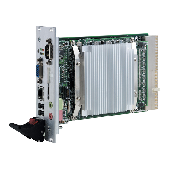
Introduction The cPCI-3840 is designed to be a high performance dual slot 3U CompactPCI CPU Module. It features a single Intel® Pentium® M processor with 1MB L2 cache in a 478-pin Micro-FCPGA package, and is validated with the Intel® 855GME chipset that supports 144-bit wide PC2100/2700 (266/333 MHz) registered ECC DDR DIMM up to a maximum of 2GB. - Page 11 each display device, digital video output with 165 MHz output clock on a 12-bit interface via one port DVO supporting pixel reso- lution up to 1600x1200 at 85Hz, Tri-view support through a LFP interface, DVO and CRT, and a maximum of 64 MB of dynamic video memory allocation.
-
Page 12: Figure 1-1: Cpci-3840 Architecture
Figure 1-1: cPCI-3840 Architecture Introduction Artisan Technology Group - Quality Instrumentation ... Guaranteed | (888) 88-SOURCE | www.artisantg.com... -
Page 13: Features
1.1 Features The features of the cPCI-3840 are as follows: Designed for Micro-FCPGA478/ Micro-FCBGA479 Pen- tium-M 400MHz PSB processor with 1MB L2 cache Supports up to two double-sided 200-pin SODIMMs with up to a total of 2GB of RAM with unbuffered PC2100/PC2700 DDR-SDRAM with or without ECC (64-bit data interface with ECC SODIMM, 72-bit with ECC SODIMM) One VGA output supports resolution up to 1600 x 1200 at... -
Page 14: Main Functions
1.2 Main Functions The cPCI-3840 CPU Module is designed for the Intel® Pentium® M and Celeron® M Processors. The standard cPCI-3840 CPU Module comes with a CPU socket which can be installed with a Micro-FC-PGA package CPU, including the following options: Pentium®... -
Page 15: Gigabit Ethernet Ports
Gigabit Ethernet Ports The cPCI-3840 has two 10/100/1000Mbps Ethernet (GbE) ports. Every port is assigned a unique static MAC Address. The BIOS menu can be setup to disable or enable these two LAN ports. The onboard Intel® 82546EB Dual Port Gigabit Ethernet Control- ler provides two Ethernet ports. -
Page 16: Watchdog Timer
the register interface and follows standard command protocol con- ventions. Watchdog Timer The cPCI-3840 implements a 2-stage Watchdog Timer (WDT) that is embedded on the 6300ESB and can be enabled/disabled in BIOS options. The WatchDog Timer supports selectable pres- caler: approximately 1 MHz (1 us to 1 s) and approximately 1 KHz (1 ms to 10 min). -
Page 17: Specifications
1.3 Specifications Specifications of the cPCI-3840 CPU Module CompactPCI Compliancy PCI Rev. 2.1 compliant PICMG 2.0 CompactPCI Rev. 3.0 Compliant PICMG 2.1 CompactPCI Hot Swap Specification R2.0 Com- pliant Form Factor Standard 3U CompactPCI: 160 mm x 100 mm board size Dual Slot, 8TE/HP width CPU/Cache Single Intel®... - Page 18 CompactPCI Bus Controller Intel® 6300ESB PCI Bus Interface Controller PCI Local Bus Specification Revision 2.2 compaliant Support 32-bit/33MHz Graphic Integrated in 855GME Graphics Memory Control Hub. Shared memory, up to 32MB Dual Channel Display Front Panel analog VGA DB-15 connector is available Gigabit Ethernet Dual 10/100/1000bps Gigabit Ethernet ports provided by Intel®...
- Page 19 Front Panel LED Indicators and Reset 4 LEDs on the front panel including storage access LED (red), Power LED (green), General Purpose Status (Blue), and Watchdog timer LED (Yellow) Flush tact switch for system reset Real -Time Clock and Nonvolatile Memory Built-in Intel®...
-
Page 20: Cpci-R3840 Rtm Specifications
Power Requirements Full Loading +3.3V Total Power Pentium® M 1.6GHz CPU, 3.16A 2.39A 23.6878 W 512MB x 2 DDR, 40G HD Pentium® M 1.1GHz CPU, 1.875A 1.746A 15.1368 W 512MB x 2 DDR, 40G HD Celeron M 1.3GHz CPU, 2.44A 1.683A 17.7539 W 512MB x 2 DDR, 40G HD Dothan... -
Page 21: I/O Connectivity Table
I/O Connectivity Table cPCI-3840 cPCI-R3840 Face-plate On-board Face-plate\ On-board Serial Port (COM1) DB-9 Serial Port (COM2) DB-9 USB (port 1, port 2) USB (port 3) Gigabit Ethernet Port 1 RJ-45 RJ-45 Gigabit Ethernet Port 2 44-pin General Purpose LED Reset button Speaker Out MIC In SATA... - Page 22 CPU Module: The cPCI-3840 CPU Module (CPU, RAM, and HDD specifi- cations will differ depending on options selected) Heat sink kit (incl. thermal pad and heat sink paste) HDD bracket SATA Cable and SATA power cable 44-pin IDE cable ADLINK All-in-One CD This user’s manual RTM: cPCI-R3840 RTM...
- Page 23 Introduction Artisan Technology Group - Quality Instrumentation ... Guaranteed | (888) 88-SOURCE | www.artisantg.com...
-
Page 24: Jumpers And Connectors
Jumpers and Connectors This chapter illustrates the board layout, connector pin assign- ments, and jumper setup. Users should familiarize themselves with the products before use. The following sections are included: cPCI-3840 board outline cPCI-3840 connectors pin assignments cPCI-3840 jumpers setting cPCI-R3840 RTM board outline cPCI-R3840 RTM connectors pin assignments Jumpers and Connectors... -
Page 25: Cpci-3840 Board Outline
2.1 cPCI-3840 Board Outline Figure 2-1: cPCI-3840 Front View and Top View Figure 2-2: cPCI-3840 Carrier Board Top View A Clear CMOS jumper (JP2) C CF connector (IDE0) Slim-type IDE (IDE1) D CF master/slave (CN5) Table 2-1: Jumper and Connector Locations Jumpers and Connectors Artisan Technology Group - Quality Instrumentation ... -
Page 26: Cpci-3840 Connector Pin Assignments
2.2 cPCI-3840 Connector Pin Assignments USB Connectors SIGNAL USB- USB+ Ground Ethernet (RJ-45) Connector Pin # Signal Name Function LAN_TDP1 Transmit Data1 + LAN_TDN1 Transmit Data1 - LAN_RDP2 Receive Data2 + LAN_RDP3 Receive Data3 + LAN_RDN3 Receive Data3 - LAN_RDN2 Receive Data2 + LAN_TDP4 Transmit Data4 +... -
Page 27: Vga Connector
Link Amber Amber 1000 Mbps (1000 BaseT) Active Blinking Amber Amber Table 2-2: Ethernet LED Status VGA Connector Signal Name Pin Pin Signal Name Green Blue N.C. N.C. DDCDAT HSYNC VSYNC DDCCLK Jumpers and Connectors Artisan Technology Group - Quality Instrumentation ... Guaranteed | (888) 88-SOURCE | www.artisantg.com... -
Page 28: Rs-232 Db-9 Serial Port Connector (Com1)
RS-232 DB-9 Serial Port Connector (COM1) Pin # RS-232 DCD, Data carrier detect RXD, Receive data TXD, Transmit data DTR, Data terminal ready IsoGND, Isolated ground DSR, Data set ready RTS, Request to send CTS, Clear to send RI, Ring indicator SATA Connector Pin Signal Pin Signal Jumpers and Connectors... -
Page 29: Ide Connector
IDE Connector Signal Name Pin Pin Signal Name BRSTDRVJ DDP7 DDP8 DDP6 DDP9 DDP5 DDP10 DDP4 DDP11 DDP3 DDP12 DDP2 DDP13 DDP1 DDP14 DDP0 DDP15 PDDREQ PDIOWJ PDIORJ PIORDY PCSEL PDDACKJ IRQ14 DAP1 DIAG DAP0 DAP2 CS1P CS3PJ IDEACTPJ Jumpers and Connectors Artisan Technology Group - Quality Instrumentation ... -
Page 30: Compactflash Connector
CompactFlash Connector Pin Signal Pin Signal Pin Signal SDIOWJ IRQ15 PCSEL CS1J 24 IOIS16J 41 BRSTDRVJ SDIORDY DD11 SDACKJ DD12 IDEACTJ DD13 DIAG DD14 DD15 CS3J DD10 34 SDIORJ General Purpose LED Definitions Color Status Description IDE idle IDE Media Access IDE access System is not power-on or power failed Power OK... -
Page 31: Compactpci J2 Pin Assignment
CompactPCI J2 Pin Assignment 22 GND GA4(2) GA3(2) GA2(2) GA1(2) GA0(2) 21 GND CLK6 BRSV(1) BRSV(1) BRSV(1) 20 GND CLK5 BRSV(1) BRSV(1) 19 GND ICMBSDA(1) ICMBSCL(1) ICMBALR(1) GND 18 GND BRSV(1) BRSV(1) BRSV(1) BRSV(1) 17 GND BRSV(1) PRST# REQ6# GNT6# 16 GND BRSV(1) BRSV(1) DEG# BRSV(1) -
Page 32: Compactpci J3 Pin Assignment
CompactPCI J3 Pin Assignment 19 GND 18 GND LPA_DA+ LPA_DA- LPA_DC+ LPA_DC- 17 GND LPA_DB+ LPA_DB- LPA_DD+ LPA_DD- 16 GND LPB_DA+ LPB_DA- LPB_DC+ LPB_DC- 15 GND LPB_DB+ LPB_DB- LPB_DD+ LPB_DD- 14 GND 2.5V 13 GND LANA_1G# LANA_100# ACTA# LINKA# LANB_1G# GND 12 GND LINKB# LANB_100#... -
Page 33: Reset Button (Sw1)
Reset Button (SW1) SW1 is a push-button on the front panel. Pressing SW1 generates a hard reset. CF Master/Slave Setting (CN5) CN5 is 3-pin jumper that can select CF device to be IDE master/ slave (see Figure 1b above for its location on the carrier board). Status Slave (Default) Master... -
Page 34: Table 2-5: Jp2 Clear Cmos
Please follow the following steps to erase the CMOS RAM data: 1. Remove the cPCI-3840 CPU Module from chassis. 2. Short pins 2 and 3 of JP2, then reinstall the jumper to normal location. 3. Insert the CPU Module back into the chassis. Status Normal operation (Default) Clear CMOS... -
Page 35: Cpci-R3840 Rtm Board Outline
2.4 cPCI-R3840 RTM Board Outline The cPCI-R3840 is a rear transition module designed for the cPCI- 3840. It comes with one LAN port, one USB port, one DVI connec- tor, and one DB-9 serial port. Figure 2-3: cPCI-R3840 Front View and Top View Jumpers and Connectors Artisan Technology Group - Quality Instrumentation ... -
Page 36: Figure 2-4: Side View Of Cpci-R3840
Figure 2-4: Side View of cPCI-R3840 Jumpers and Connectors Artisan Technology Group - Quality Instrumentation ... Guaranteed | (888) 88-SOURCE | www.artisantg.com... -
Page 37: Cpci-R3840 Rtm Connector Pin Assignments
2.5 cPCI-R3840 RTM Connector Pin Assignments The connector pin assignments of the cPCI-R3840 Rear Transi- tion Module’s RJ-45 GbE port, USB port, and DB-9 serial port COM2 are identical to those of the cPCI-3840 CPU Module. Please refer to Section 2.2. The pin assignments for the DVI connector and RJ2 connector are as follows: DVI Connector... -
Page 38: Cpci-R3840 Rj2 Pin Assignment
cPCI-R3840 RJ2 Pin Assignment RJ2-22 RJ2-21 CLK6 ICLKAP 1000LEDJ IYAP3 RJ2-20 CLK5 ICLKAM IYAM3 RJ2-19 SMBDATA SMBCLK SMBALERT GND RJ2-18 IYAP1 IYAP2 IYAM2 100LEDJ RJ2-17 IYAM1 PRST# REQ6# GNT6# RJ2-16 IYAP0 ACLEDJ DEG# LILEDJ RJ2-15 IYAM0 FAL# REQ5# GNT5# RJ2-14 COM2_RIJ COM2_TXD COM2_DTRJ... - Page 39 Jumpers and Connectors Artisan Technology Group - Quality Instrumentation ... Guaranteed | (888) 88-SOURCE | www.artisantg.com...
-
Page 40: Getting Started
Getting Started This chapter provides information on how to install necessary components for the cPCI-3840 and cPCI-R3840 RTM, including: CPU installation Memory module installation CF installation CPU Core Module removal and installation Heat sink and 2.5” HDD installation cPCI-3840 CPU Module installation cPCI-3840 RTM installation Depending on the options selected for your cPCI-3840, installation of the CPU, RAM, heat sink, and HDD may or may not be... -
Page 41: Installing The Cpu
3.1 Installing the CPU The cPCI-3840 supports the Intel® Pentium® M and Celeron® M processors. The CPU socket is located in the middle of the CPU Core Module as shown in Figure 4 below. Remove the CPU from its packaging and place it carefully in the CPU socket as shown in Figure 4 below. -
Page 42: Memory Module Installation
3.2 Memory Module Installation The cPCI-3840 CPU Module supports 144-bit wide PC2100/ PC2700 registered/unregistered ECC DDR DIMM up to 2GB max- imum. Two memory sockets are located on the CPU Core Module (one on each side). If memory modules are pre-installed when the package is received, this section may be skipped. -
Page 43: Removing The Cpu Core Module
Removing the CPU Core Module The second memory socket is located on the underside of the CPU Core Module. If installation of a second memory socket is necessary, first remove the CPU Core Module by loosening the 4 screws that attach it to the carrier board. Then carefully lift it upwards by grasping it with thumb and forefinger at the points marked GRIP HERE shown in Figure 5b. -
Page 44: Installing The Second Memory Module
Installing the Second Memory Module Insert the second memory module into the slot shown in the figure below using the same procedure as described above for installa- tion of the first memory module. Figure 3-4: Memory Module Installation, Pt. 2. Getting Started Artisan Technology Group - Quality Instrumentation ... -
Page 45: Cf Card Installation
3.3 CF Card Installation The CF card slot is located on the carrier board of the cPCI-3840. The CF card can be inserted and ejected with the CPU Core Mod- ule in place. However, if you are installing a second memory mod- ule, it is easier to install the CF card when the CPU Core Module has been removed. -
Page 46: Figure 3-5: Thermal Pad
Figure 3-5: Thermal Pad Apply the thermal pad to the CPU (white side down) and remove the Mylar film from the top (pink) side of the thermal pad. Getting Started Artisan Technology Group - Quality Instrumentation ... Guaranteed | (888) 88-SOURCE | www.artisantg.com... -
Page 47: Figure 3-6: Heat Sink Fitting
Figure 3-6: Heat Sink Fitting Remove the Mylar Film covering the gray thermal pad on raised block. (Note orientation of heat sink to 855GME North Bridge.) Getting Started Artisan Technology Group - Quality Instrumentation ... Guaranteed | (888) 88-SOURCE | www.artisantg.com... -
Page 48: Figure 3-7: Heat Sink Screws
Figure 3-7: Heat Sink Screws Remove the Mylar Film covering the gray thermal pad on raised block. (Note orientation of heat sink to 855GME North Bridge.) Getting Started Artisan Technology Group - Quality Instrumentation ... Guaranteed | (888) 88-SOURCE | www.artisantg.com... -
Page 49: Hdd Installation
3.6 2.5” HDD Installation To install a 2.5” hard drive, it is first necessary to install the mount- ing brackets. Follow the figure below for the installation procedure. Getting Started Artisan Technology Group - Quality Instrumentation ... Guaranteed | (888) 88-SOURCE | www.artisantg.com... -
Page 50: Figure 3-8: Hdd And Mounting Bracket Installation
Then attach the IDE connector. Figure 3-8: HDD and Mounting Bracket Installation Getting Started Artisan Technology Group - Quality Instrumentation ... Guaranteed | (888) 88-SOURCE | www.artisantg.com... -
Page 51: Cpci-3840 Cpu Module Installation
3.7 cPCI-3840 CPU Module Installation Use the following procedure to install the cPCI-3840 CPU Module to its CompactPCI chassis. 1. Refer to the relevant chassis user manual for pre-prepa- ration of the chassis before installing the main board. Users need to assign a slot to the board. Be sure to select the correct slot (system or peripheral) depending on the operational purpose of the board. -
Page 52: Rtm Installation
RTMs. Refer to previous sections for peripheral connectivity of all I/O ports on the RTM. When installing the cPCI-3840 series and related RTMs, make sure the RTM is the correct matching model. Note: Use the correct RTM to enable functions (I/O interfaces) on rear side. - Page 53 Getting Started Artisan Technology Group - Quality Instrumentation ... Guaranteed | (888) 88-SOURCE | www.artisantg.com...
-
Page 54: Windows Driver Installation
Windows Driver Installation The following sections show the driver installation procedures for Windows 2000, Windows XP and Windows Server 2003. When installing the Windows drivers, we recommend the following steps: 1. Fully install Windows properly before installing any driver. Most of the standard I/O device drivers are included in Windows. -
Page 55: Chipset Drivers Installation
4.1 Chipset Drivers Installation 1. Ensure Windows 2000/XP/Server 2003 is fully installed and running prior to executing the “Intel Chipset Soft- ware Installation Utility”. 2. Close any running applications. 3. The files are stored in an integrated application setup program. This program is designed for Windows 2000, XP and Server 2003. -
Page 56: Lan Driver Installation
4.3 LAN Driver Installation This section describes the LAN driver installation for the Intel® 82546EB onboard Ethernet controllers. 1. Run pro2kxp.exe located in the following directory: X:\cPCI\cPCI-3840\LAN. 2. Read the license agreement. Click 'I accept the terms in the license agreement’ if you agree to continue. 3. - Page 57 Windows Driver Installation Artisan Technology Group - Quality Instrumentation ... Guaranteed | (888) 88-SOURCE | www.artisantg.com...
-
Page 58: Utilities
Utilities 5.1 Watchdog Timer This section explains the operation of the cPCI-3840’s watchdog timer. It provides an overview of watchdog operation and features, as well as a sample code to help you learn how the watchdog timer works. WDT Overview The primary function of the watchdog timer is to monitor the cPCI- 3840’s operation and to generate IRQs or reset the system if the software fails to function as programmed. -
Page 59: Configuration Registers
The cPCI-3840’s custom watchdog timer circuit is integrated into the south bridge 6300ESB. The Intel® 6300ESB ICH includes a two-stage Watchdog Timer (WDT) that provides a resolution ranging from one micro second to ten minutes. The timer uses a 35-bit Down-Counter. The counter is loaded with the value from the first Preload register. - Page 60 The register unlocking sequence is necessary when writing to the Preload registers. The following is the procedure of how to write a value into preload value 1 and 2 register. 1. Write 80H to offset BAR + 0CH. 2. Write 86H to offset BAR + 0CH. 3.
-
Page 61: Gpio Control Registers
Offset 68H: WDT Lock Register Bit 2 is used to choose the functionality of the timer. (0 = Watchdog Timer mode, 1 = Free running mode) The free run- ning mode ignores the first stage and only uses Preload Value 2. -
Page 62: Wdt Programming Procedure
WDT LED Control GPO25 of the 6300ESB is designed to control WDT LED. Two features of the WDT LED are supported on cPCI-3840. WDT LED lights or blinks. WDT LED lights: Set bit 25 of GPIOBASE + 04H to 0. Bit 25 of GPIOBASE + 0CH determines the state of WDT LED. -
Page 63: Utilities
Intel® driver download center. 5.2 Intel® Preboot Execution Environment (PXE) The cPCI-3840 series supports Intel® Preboot Execution Environ- ment (PXE), which provides the capability of boot up or executing an OS installation through the Ethernet ports. There should be a DHCP server in the network with one or more servers running PXE and MTFTP services. -
Page 64: Warranty Policy
Warranty Policy Thank you for choosing ADLINK. To understand your rights and enjoy all the after-sales services we offer, please read the follow- ing carefully. 1. Before using ADLINK’s products please read the user man- ual and follow the instructions exactly. When sending in damaged products for repair, please attach an RMA appli- cation form which can be downloaded from: http:// rma.adlinktech.com/policy/. - Page 65 3. Our repair service is not covered by ADLINK's guarantee in the following situations: Damage caused by not following instructions in the User's Manual. Damage caused by carelessness on the user's part dur- ing product transportation. Damage caused by fire, earthquakes, floods, lightening, pollution, other acts of God, and/or incorrect usage of voltage transformers.
- Page 66 Artisan Technology Group is your source for quality new and certified-used/pre-owned equipment SERVICE CENTER REPAIRS WE BUY USED EQUIPMENT • FAST SHIPPING AND DELIVERY Experienced engineers and technicians on staff Sell your excess, underutilized, and idle used equipment at our full-service, in-house repair center We also offer credit for buy-backs and trade-ins •...
Need help?
Do you have a question about the cPCI-3840 Series and is the answer not in the manual?
Questions and answers