
Subscribe to Our Youtube Channel
Related Manuals for ADLINK Technology cPCI-R6100


Summary of Contents for ADLINK Technology cPCI-R6100
- Page 1 ® 6U CompactPCI Rear Transition Module User’s Manual Manual Rev.: Revision Date: July 3, 2018 Part No: 50-15108-1000 Leading EDGE COMPUTING...
- Page 2 Leading EDGE COMPUTING Revision History Revision Release Date Description of Change(s) 2018/07/03 Initial release Revision History...
-
Page 3: Preface
Preface Copyright 2018 ADLINK Technology, Inc. This document contains proprietary information protected by copy- right. All rights are reserved. No part of this manual may be repro- duced by any mechanical, electronic, or other means in any form without prior written permission of the manufacturer. - Page 4 Leading EDGE COMPUTING California Proposition 65 Warning WARNING: This product can expose you to chemicals including acrylamide, arsenic, benzene, cadmium, Tris(1,3-dichloro-2-propyl)phosphate (TDCPP), 1,4-Diox- ane, formaldehyde, lead, DEHP, styrene, DINP, BBP, PVC, and vinyl materials, which are known to the State of California to cause cancer, and acrylamide, benzene, cadmium, lead, mercury, phthalates, toluene, DEHP, DIDP, DnHP, DBP, BBP, PVC, and vinyl materials, which are known to the State of California to cause...
-
Page 5: Table Of Contents
1 Introduction ................ 1 Overview................1 Features................2 Package Contents ............... 3 2 Specifications ..............5 cPCI-R6100 Series Specifications........5 Block Diagram ..............7 3 Board Interfaces ..............9 cPCI-R6100 Board Layout........... 9 cPCI-R6110/6120 Board Layout........11 Connector Pin Assignments ..........13 Switch Settings .............. - Page 6 Leading EDGE COMPUTING This page intentionally left blank. Table of Contents...
-
Page 7: List Of Figures
List of Figures Figure 2-1: cPCI-R6100 Functional Block Diagram ......7 Figure 3-1: cPCI-R6100 Board Layout - Component Side....9 Figure 3-2: cPCI-R6100 SW1/SW2 Locations - Solder Side ... 10 Figure 3-3: cPCI-R6110/6120 Board Layout........11 List of Figures... - Page 8 Leading EDGE COMPUTING This page intentionally left blank. viii List of Figures...
-
Page 9: List Of Tables
List of Tables Table 2-1: cPCI-R6100 Series Specifications........6 Table 3-1: DVI-D Connector Pin Definition ........13 Table 3-2: Front Panel COM Pin Definitions........14 Table 3-3: COM RJ-45 to DB-9 Cable Pin Definitions ....14 Table 3-4: VGA Pin Definition ............15 Table 3-5: DB-6920SAT/DB-6920CF Connector Pin Definition.. - Page 10 Leading EDGE COMPUTING This page intentionally left blank. List of Tables...
-
Page 11: Introduction
Introduction 1.1 Overview The cPCI-R6100 Series is a 6U CompactPCI® rear transition module (RTM) in single/dual slot (4/8HP) width form factor featur- ing up to quad Ethernet RJ-45 interfaces provided by an Intel® Ethernet Controller I350-AM2. The cPCI-R6100 Series provides rich I/O interfaces to maximize the flexibility of the processor blade with up to four Ethernet RJ-45 ports, four USB 2.0, one DVI-D, one VGA, one RJ-45 serial port... -
Page 12: Features
Two Gigabit Ethernet ports from onboard Intel® Ethernet Controller I350-AM2 Two Gigabit Ethernet ports from processor blade by PICMG 2.16 (cPCI-R6100 only) One PS/2 keyboard mouse on faceplate Two SATA 7-pin connectors, CF card slot, SD card slot 2.5” drive space on cPCI-R6110, space for additional 2.5” drive... -
Page 13: Package Contents
1.3 Package Contents The cPCI-R6100/cPCI-R6110/cPCI-R6120 is packaged with the following components. If any of the items on the contents list are missing or damaged, retain the shipping carton and packing mate- rial and contact the dealer for inspection. Please obtain authoriza- tion before returning any product to ADLINK. - Page 14 Wear an anti-static wrist strap properly grounded on one of the system's ESD ground jacks when installing or servicing system components. The contents of non-standard cPCI-R6100 Series configu- rations may vary depending on the customer requests. NOTE: NOTE:...
-
Page 15: Specifications
• CompactPCI® Packet Switching Backplane Specification PICMG 2.16 Rev. 1.0 Form Factor • Standard 6U CompactPCI® Rear Transition Module • Board size: 233.35mm x 80mm • cPCI-R6100, cPCI-R6110: single slot (4HP, 20.32mm) • cPCI-R6120: dual-slot (8HP, 40.64mm) • CompactPCI® connectors rJ3 and rJ5 Onboard cPCI-R6100 Peripherals •... -
Page 16: Table 2-1: Cpci-R6100 Series Specifications
• Optional Gold Cap for RTC backup power in case there is no battery on the processor blade Table 2-1: cPCI-R6100 Series Specifications Windows does not support USB as host boot device. Therefore, a CompactFlash card cannot be used to install a Windows operating system. -
Page 17: Block Diagram
GbE a Intel PCIe x4 I350-AM2 GbE b TMDS DVI-D SATA 3 7 pin Rechargeable battery SATA 2 7 pin SATA 1 2.5” HDD/CF 4x USB 2.0 GbE c, d (PICMG 2.16) PS/2 USB2251i Figure 2-1: cPCI-R6100 Functional Block Diagram Specifications... - Page 18 Leading EDGE COMPUTING This page intentionally left blank. Specifications...
-
Page 19: Board Interfaces
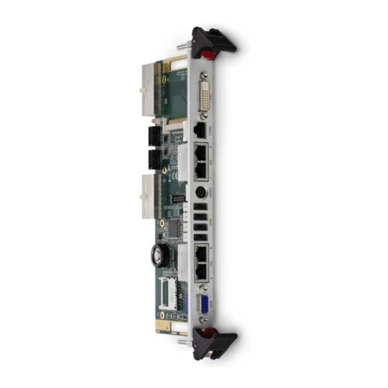
2x GbE ports from 2x GbE ports from Intel PICMG 2.16 (GbE c/d) I350-AM2 (GbE a/b) CN1/2/3/4 USB 2.0 ports PS/2 keyboard/mouse connector CN10 DVI-D connector CN14 RJ-45 serial port Figure 3-1: cPCI-R6100 Board Layout - Component Side Board Interfaces... -
Page 20: Figure 3-2: Cpci-R6100 Sw1/Sw2 Locations - Solder Side
Leading EDGE COMPUTING cPCI-R6100 SW1/SW2 Locations SW2 SW1 Figure 3-2: cPCI-R6100 SW1/SW2 Locations - Solder Side Board Interfaces... -
Page 21: Cpci-R6110/6120 Board Layout
3.2 cPCI-R6110/6120 Board Layout cPCI-R6110 and cPCI-R6120 share the same board layout with the only difference being the 8HP front panel on the cPCI-R6120 to allow space for an additional 2.5" SATA drive. cPCI-R6110 CN11 CON1 CN10 CN12 CN4/3/2/1 CN5... - Page 22 Leading EDGE COMPUTING Intel I350-AM2 GbE DB-6920SAT connector controller USB 2.0 Flash Card DB-15 VGA connector Reader Controller CON1 SD card holder CN8/10 SATA ports (7-pin) Gold Cap battery (not CN11 SATA 5-pin power populated by default) connector PS/2 keyboard/mouse CN12 CompactFlash socket connector...
-
Page 23: Connector Pin Assignments
3.3 Connector Pin Assignments Faceplate Connectors DVI-D Connector Pin # Signal Pin # Signal TMDS Data2- TMDS Data3+ TMDS Data2+ +5 V Power TMDS Data2/4 Shield TMDS Data4- Hot Plug Detect TMDS Data4+ TMDS Data0- DDC Clock [SCL] TMDSData0+... -
Page 24: Table 3-2: Front Panel Com Pin Definitions
Leading EDGE COMPUTING RJ-45 Serial Port Pin # RS-232 DCD# RTS# DSR# CTS# DTR#L Table 3-2: Front Panel COM Pin Definitions COM RJ-45 to DB-9 Cable Pin # RS-232 DCD# DTR#L DSR# RTS# CTS# — Table 3-3: COM RJ-45 to DB-9 Cable Pin Definitions Board Interfaces... -
Page 25: Table 3-4: Vga Pin Definition
PS/2 Keyboard/Mouse Port Pin # Signal Function KB_DATA Keyboard Data MS_DATA Mouse Data Ground KM_VCC Power KB_CLK Keyboard Clock MS_CLK Mouse Clock USB 2.0 Type A Connectors Pin # Signal Name USB_D- USB_D+ DB-15 VGA Connector Signal Name Pin # Pin # Signal Name... - Page 26 Leading EDGE COMPUTING GbE Connectors (RJ-45) 10BASE-T/ Pin # 1000BASE-T 100BASE-TX LAN_TX0P LAN_TX0N LAN_TX1P LAN_TX2P LAN_TX2N Speed Activity LAN_TX1N LAN_TX3P LAN_TX3N Speed LED Activity LED Status (Green/Amber) (Amber) Network link is not established or system powered off Link 10 Mbps Active Blinking Link...
- Page 27 Onboard Connectors SATA Connectors Pin # Signal SATA Power Connector Pin # Signal P12V Board Interfaces...
-
Page 28: Table 3-5: Db-6920Sat/Db-6920Cf Connector Pin Definition
Leading EDGE COMPUTING DB-6920SAT/DB-6920CF Daughter Board Connector Signal Name Pin # Pin # Signal Name P3V3 P3V3 P3V3 P3V3 P1V8 P1V8 P1V8 SATA-TXN0 SATA-TXP0 SATA-RXN0 SATA-RXP0 RESET# Table 3-5: DB-6920SAT/DB-6920CF Connector Pin Definition Board Interfaces... -
Page 29: Table 3-6: Compactpci Rj3 Connector Pin Definition
CompactPCI rJ3 Connector Pin Z 19 GND P12V LANBB_TXDP0 LANBB_TXDN0 LANBB_TXDP2 LANBB_TXDN2 18 GND LANBB_TXDP1 LANBB_TXDN1 LANBB_TXDP3 LANBB_TXDN3 17 GND LANBA_TXDP0 LANBA_TXDN0 LANBA_TXDP2 LANBA_TXDN2 16 GND LANBA_TXDP1 LANBA_TXDN1 LANBA_TXDP3 LANBA_TXDN3 15 GND USB-OC5-L USB-OC2-L USB-OC3-L USB-OC0-L USB-OC1-L 14 GND... -
Page 30: Table 3-7: Compactpci Rj5 Connector Pin Definition
Leading EDGE COMPUTING CompactPCI rJ5 Connector LANBA_LINK_ LANBB_LINK_ 22 GND P3V3_LAN P3V3_LAN ACT-L ACT-L 21 GND 20 GND 19 GND 18 GND 17 GND 16 GND 15 GND SATA-R5P SATA-R5N 14 GND SATA-T5P SATA-T5N 13 GND LANBA_100-L LANBB_100-L LANBB_1G-L LANBA_1G-L 12 GND MDVIDATA MDVICLK... -
Page 31: Switch Settings
3.4 Switch Settings PICMG 2.16 LAN Switches (SW1, SW2) The cPCI-R6100 can route LAN signals from the CPU blade to either the PICMG 2.16 backplane or to GbE c and GbE d on the faceplate I/O (but not both simultaneously). The following... - Page 32 Leading EDGE COMPUTING This page intentionally left blank. Board Interfaces...
-
Page 33: Getting Started
Getting Started The cPCI-R6110/cPCI-R6120 provide space onboard to mount a 2.5" storage device. 4.1 Installing a 2.5" SATA Drive Follow the steps below to install a 2.5” SATA drive on the cPCI-R6110/cPCI-R6120. 1. Find the DB-6920SAT adapter and 2.5" SATA drive kit in the package. - Page 34 Leading EDGE COMPUTING 3. Align the SATA drive and adapter board on the cPCI-R6110/cPCI-R6120 as shown below and press it onto the board-to-board connector CN6. Fasten the two M2.5 4mm screws as shown. 4. Fasten the four M3 4mm screws from the back side as shown below to secure the SATA drive to the RTM.
-
Page 35: 2Nd 2.5" Sata Drive On Cpci-R6120
4.2 2nd 2.5" SATA drive on cPCI-R6120 The cPCI-R6120 provides space on layer 2 to install one addi- tional 2.5" SATA drive. Follow the instructions below to install the additional 2.5" SATA drive to the cPCI-R6120. 1. Find the SATA bracket, cable and screw kit. Assemble the bracket to the SATA drive, attached the cable to the SATA drive, and fasten the four M2.5 6mm screws as... - Page 36 Leading EDGE COMPUTING 2. Place the drive assembly onto the cPCI-R6120 as shown below. Insert the SATA connector into CN8. 3. Fasten the four M3 8mm screws from the back side as shown below to secure the drive assembly to the RTM. Getting Started...
-
Page 37: Important Safety Instructions
Important Safety Instructions For user safety, please read and follow all instructions, WARNINGS, CAUTIONS, and NOTES marked in this manual and on the associated equipment before handling/operating the equipment. Read these safety instructions carefully. Keep this user’s manual for future reference. - Page 38 Leading EDGE COMPUTING Never attempt to fix the equipment. Equipment should only be serviced by qualified personnel. A Lithium-type battery may be provided for uninterrupted, backup or emergency power. Risk of explosion if battery is replaced with one of an incorrect type.
-
Page 39: Getting Service
San Jose, CA 95138, USA Tel: +1-408-360-0200 Toll Free: +1-800-966-5200 (USA only) Fax: +1-408-360-0222 Email: info@adlinktech.com ADLINK Technology (China) Co., Ltd. 300 Fang Chun Rd., Zhangjiang Hi-Tech Park Pudong New Area, Shanghai, 201203 China Tel: +86-21-5132-8988 Fax: +86-21-5132-3588 Email: market@adlinktech.com...
Need help?
Do you have a question about the cPCI-R6100 and is the answer not in the manual?
Questions and answers