Table of Contents
Advertisement
Quick Links
Advertisement
Table of Contents

Related Manuals for RayTek GP Series


Summary of Contents for RayTek GP Series
-
Page 1: Operating Instructions
GP Series Operating Instructions Rev. F 10/2011 54201... - Page 3 ARRANTY The manufacturer warrants this instrument to be free from defects in material and workmanship under normal use and service for the period of two years from date of purchase. This warranty extends only to the original purchaser. This warranty shall not apply to fuses, batteries, or any product that has been subject to misuse, neglect, accident, or abnormal conditions of operation.
-
Page 4: Table Of Contents
3.3.1 Terminal Block Layout ........11 3.3.2 Raytek Sensor Model GP ........13 3.3.3 Raytek Sensor Model XR ........13 3.3.4 Raytek Sensor Models CI3, CM, TX ....13 3.3.5 Common Input Devices ........14 3.3.6 Power Connections ........... 16 3.3.7 Output Connections ......... - Page 5 3.4.4 Setpoints 1 and 2 ..........23 3.4.5 Analog 4 - 20 mA Output ........ 27 3.4.6 Degrees C and F ..........28 3.4.7 Signal Processing ..........29 3.4.8 Ambient Temperature Compensation ....30 3.4.9 Display and Analog Output Offset ....31 3.4.10 Thermocouple Output........
- Page 6 6 MAINTENANCE ............57 6.1 F ..........58 PERATION 6.2 C ..........58 LEANING THE 7 APPENDIX ..............60 7.1 D ......60 ETERMINATION OF MISSIVITY 7.2 T ........61 YPICAL MISSIVITY ALUES 8 NOTES ................65...
-
Page 8: Safety Instructions
Use only original parts and accessories approved by the manufacturer. The use of other products can compromise the operational safety and functionality of the instrument. Instrument Disposal Disposal of old instruments should be handled according professional environmental regulations as electronic waste. Rev. F 10/2011 GP Series... - Page 9 Pay attention to possible reflections of the laser beam. The laser functions only to locate and mark surface measurement targets. Do not aim the laser at people or animals. Rev. F 10/2011 GP Series...
- Page 10 Use in 110 / 230 VAC electrical systems can result in electrical hazards and personal injury if not properly protected. All instrument parts supplied by electricity must be covered to prevent physical contact and other hazards at all times. Rev. F 10/2011 GP Series...
-
Page 11: Description
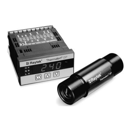
GP monitor accepts inputs from any 0-5V and 4-20mA devices, which allows it to be used as a panel meter for many applications. Other settings allow the GP to act as a temperature monitor for Raytek fixed infrared sensors like GPR, GPS, CI3, CM, TX and XR and for other temperature gathering devices. -
Page 12: Gp Monitor
0 to 998 s (999=infinite hold) Valley Hold: 0 to 998 s (999=infinite hold) Averaging: 0 to 60 s Fail-Safe: Full or low scale, depending upon system failure, see section 6.1 Fail-Safe Operation, Seite 58. Rev. F 10/2011 GP Series... -
Page 13: Electrical Specifications
Mechanical Relay: AC contact: 250 VAC, 3 A GPCM Monitor DC contact: 30 VDC, 3 A 3.1.3 Environmental Specifications Dimensions: 1/8 DIN, 118 mm length (1.75 x 3.63 x 4.75 in) Weight: 320 g (0.7 lbs) Rev. F 10/2011 GP Series... -
Page 14: Mounting Instructions
3. Attach the fixing clamps to both sides of the monitor. Make sure the tab is secure in the hole on both sides. 4. Fix the monitor with the clamp screws! Rev. F 10/2011 GP Series... -
Page 15: Mounting Bracket Accessory
Monitor to a wall, post, column, or other flat surface, complete the following steps: 1. Insert the rear of the monitor through the bracket’s opening so the bottom of the monitor rests on the bracket surface. Make sure the gasket is in place Figure 3. Rev. F 10/2011 GP Series... - Page 16 You might need to loosen the fixing clamp screws first, see Figure 4. Tighten Fixing Clamp Screws Before mounting bracket, connect wires and attach rear cover Figure 4: Completing the Installation Rev. F 10/2011 GP Series...
-
Page 17: Cutout Template And Cosmetic Frame
To install, simply insert the frame between the monitor bezel and mounting gasket prior to inserting the monitor into the panel. Rev. F 10/2011 GP Series... -
Page 18: Electrical Installation
GP Monitor Mark around inside edges Figure 5: 1/8 DIN Cutout Template and Cosmetic Frame 3.3 Electrical Installation 3.3.1 Terminal Block Layout Either soldered spade lugs or bare wires are acceptable for connections. Rev. F 10/2011 GP Series... - Page 19 18 no connection 9 24 VDC output power (50 mA max) 19 N Neutral (power) 10 Input 3 (4 - 20 mA or GPR/GPS) 20 H Hot (power) * see Table 8 Output Connections, page 18 Rev. F 10/2011 GP Series...
-
Page 20: Raytek Sensor Model Gp
Pin Monitor Function Ground Shield mA signal Table 2: Wiring XR Sensing Heads 3.3.4 Raytek Sensor Models CI3, CM, TX The following tables show wiring connections for the CI3, CM, TX sensing heads to the monitor. Rev. F 10/2011 GP Series... -
Page 21: Common Input Devices
The following tables show the wiring for sensing heads or input devices with 0-5 V and 4-20 mA outputs or thermocouples to the monitor. 0 - 5 V 4 - 20 mA Function Function Signal (-) Signal (+) Shield Shield 4 - 20 mA Input Rev. F 10/2011 GP Series... - Page 22 Use Table 6 when connecting either 0-5 V or 4-20 mA input devices that can use the 24 VDC/50 mA power available from the monitor. Make sure to unplug the unit before wiring devices or power! Rev. F 10/2011 GP Series...
-
Page 23: Power Connections
For further information see section 3.4.2 Device Selection, Seite 20. 3.3.6 Power Connections You can connect 110-220VAC, 50-60Hz, to the monitor. It can automatically sense whether you connect 110 or 220 VAC. Use Table 7 as a guide. Rev. F 10/2011 GP Series... -
Page 24: Output Connections
Thermocouple outputs (J, K, E, N, T, R, and S) Setpoints 1 und 2, optional: potential free relay contacts 4 - 20 mA Thermocouple Function Function 4-20 mA output Thermocouple (-) Analog ground Thermocouple (+) Shield Rev. F 10/2011 GP Series... -
Page 25: External Relay (Accessory)
3.4.1 Control Panel The GP Monitor consists of a control panel with 4 LED’s, 3 buttons, and 5 indicating lights. Besides displaying the current temperature or user-defined value, the LED’s also display parameter settings. By Rev. F 10/2011 GP Series... - Page 26 Before turning on the power, make sure all wiring connections are secure. Note that all controls can be adjusted while the power is on without damaging sensor or electronics, see sections 3.4.2 to 3.4.12. Rev. F 10/2011 GP Series...
-
Page 27: Device Selection
H005 = 4 – 20 mA input, e.g. Raytek TX Head H006 = Thermocouple input H007 = 4 – 20 mA input, e.g. Raytek XR Head with emissivity setting Note that all head types except H003 have additional display settings. - Page 28 On, it will be positioned at a tenth of a degree (e.g., 888.8). Press the button again to be able to select the thermocouple input type. Use the following as a guide: TC1 = J-type thermocouple input Rev. F 10/2011 GP Series...
-
Page 29: Emissivity
For H001, complete the following procedure to set emissivity. 1. In temperature mode display, press the button until a display similar to following figure appears. The “E” will be followed by numbers designating the emissivity. Rev. F 10/2011 GP Series... -
Page 30: Setpoints 1 And 2
Figure 13: Setpoint Display (Showing Setpoint 1 Active) 2. When either S1 or S2 is displayed, press the buttons to activate or deactivate the setpoint (a number “1” displays when the setpoint is active, a number “0” displays when it’s inactive). Rev. F 10/2011 GP Series... - Page 31 SP1 or SP2 value and when the trigger level (“b”) is set to either “1” or “3”. The following figures shows examples of how the setpoints change state when triggered. Rev. F 10/2011 GP Series...
- Page 32 GP Monitor Display = b 0 Trigger signal low, output normally low Signal GP Monitor Display = b 1 Trigger signal high, output normally low Signal GP Monitor Display = b 2 Trigger signal low, output normally high Signal Rev. F 10/2011 GP Series...
- Page 33 Setpoint 2. When finished with Setpoint 2, if used, pressing again takes you to the 4-20 mA output setup indicator display. To return to the temperature/value display, press the button until the temperature/value display appears. Note: Rev. F 10/2011 GP Series...
-
Page 34: Analog 4 - 20 Ma Output
3. Press the buttons to adjust the temperature value. 4. Pressing the button again brings up the 20 mA display. Figure 18: 20 mA Analog Output Display 5. Press the buttons to adjust the temperature value. Rev. F 10/2011 GP Series... -
Page 35: Degrees C And F
°C °F Function °C lit on monitor °F lit on monitor To disable °C/°F indicators (only for H004 and H005) Not available Table 9: The °C and °F Configurations Rev. F 10/2011 GP Series... -
Page 36: Signal Processing
Peak Hold value in seconds. 3. Set the display by using the buttons. Note that “000” turns off Peak Hold. 4. Press the button again and the Valley Hold display appears. Rev. F 10/2011 GP Series... -
Page 37: Ambient Temperature Compensation
3.4.8 Ambient Temperature Compensation Head type H001 only - The ambient temperature compensation is factory preset as inactive. This value is normal for most applications. However, in some applications the surrounding ambient temperature Rev. F 10/2011 GP Series... -
Page 38: Display And Analog Output Offset
6. Press the button until the temperature/value mode displays. 3.4.9 Display and Analog Output Offset To adjust and set the Display and Analog Output Offset (applies to displayed temperature and all analog outputs), complete the following steps: Rev. F 10/2011 GP Series... -
Page 39: Thermocouple Output
The Peak Hold display appears, see Figure 20. 2. Press the button several times until the thermocouple output indicator displays as shown in the following figure: Figure 25: Thermocouple Output Rev. F 10/2011 GP Series... -
Page 40: Lockout Mode
2. Press the button, the button 3 times, then release. The letter “E” displays for approximately 3 seconds showing that Lockout has been deactivated. 3. Press the button until the temperature mode displays. Rev. F 10/2011 GP Series... -
Page 41: Factory Defaults
Table 10: Factory-set Default Values 3.5 Quick Reference On the following pages are quick reference charts for setting up the GP Monitor with sensing head and input devices and for adjusting the monitor’s normal and advanced functions. Rev. F 10/2011 GP Series... - Page 42 Refer to the appropriate Sensing Head and Input Device wiring information in section 3.3 Electrical Installation, Seite 11 before continuing. For a detailed explanation of each function, refer to section 3.4 Operation, Seite 18. Rev. F 10/2011 GP Series...
- Page 43 (1) or off (2) display 2 To temperature display Select thermocouple type = Cycle through displays = Cycle through head and input displays To temperature display = Adjust values Figure 26: Head and Input Setup Rev. F 10/2011 GP Series...
- Page 44 H003, H004, H005, H006 Activate °C or °F (2 displays) Activate Setpoint 1 (4 displays) Activate Setpoint 2 (4 displays) Back to display 1 = Cycle through displays = Adjust values Figure 27: Normal Functions Rev. F 10/2011 GP Series...
- Page 45 Peak Hold Indicator (3 displays) (2 displays) Offset Indicator (2 displays) Valley Hold Indicator (2 displays) Thermocouple Output (2 displays) = Cycle through displays Back to display 1 = Adjust values Figure 28: Advanced Functions Rev. F 10/2011 GP Series...
-
Page 46: Installation Of Sensing Heads
Installation of Sensing Heads 4 Installation of Sensing Heads 4.1 Raytek Sensing Heads This section describes how to connect Raytek infrared sensing heads to the GP monitor. Raytek sensing heads include: GPR sensing head (head type H001) GPS sensing head with laser (head type H001) - Page 47 To avoid erroneous readings the target spot size must contain the entire field of view of the sensor. Consequently, the sensor must be positioned so the field of view is the same as or smaller than the desired target size. Rev. F 10/2011 GP Series...
- Page 48 It is important to keep the lens clean at all times. A clean lens can prevent erroneous readings and possible lens damage. An Air Purge Collar is available, and recommended, for all models to protect the lens from smoke, fumes, dust, and other contaminants. Rev. F 10/2011 GP Series...
-
Page 49: Mechanical Installation
For the GPR, the standard 4 m (13ft) cable is an accessory and comes with a 5-pin DIN connector on one end and bare wires on the other. Plug the DIN connector into the sensing head, and run the wire to the Rev. F 10/2011 GP Series... -
Page 50: Aiming The Sensing Head
To aim the sensor, complete the following: 1. Slightly loosen the mounting bracket’s nuts. 2. Point the sensor toward the target. 3. Move it around until the target’s temperature displays on the monitor. 4. Secure the mounting bracket. Rev. F 10/2011 GP Series... -
Page 51: Gpr/Gps Sensing Head
Make sure the inner diameter of any pipe or tube extension is not so small that it interferes with the optical field of view of the sensing head model being used. Rev. F 10/2011 GP Series... - Page 52 FDA Radiation Performance Standards, 21 CFR, subchapter J, and meets IEC 825, Class 2 specifications. Note: The laser automatically turns off after approximately 10 minutes of use. Figure 31: Dimensions for the GPS Head Rev. F 10/2011 GP Series...
- Page 53 6. Wires 7. Sensor head cable Figure 33: Laser Switching Box ARNUNG Avoid exposure to laser light. Eye damage can result. Use extreme caution when operating. Never point at a person. Be aware of reflections! Rev. F 10/2011 GP Series...
-
Page 54: Options
Water temperature should be 10-27°C (50-80°F) for efficient cooling. Using chilled water below 10°C (50°F) is not recommended. To avoid condensation, it is recommended to use the Air Purge Collar with the Water Cooled Housing. Rev. F 10/2011 GP Series... - Page 55 GPR/GPS Sensing Head Figure 35: GPR Head with Air/Water-cooled Housing Figure 36: GPS Head with Air/Water-cooled Housing Rev. F 10/2011 GP Series...
-
Page 56: Zubehör
The Air Purge Collar is used to keep dust, moisture, airborne particles, and vapors away from the lens. It can be installed before or after the mounting bracket. It must be screwed in fully. Air flows into Rev. F 10/2011 GP Series... - Page 57 1/8” NPT brass fitting and out the front aperture. Air flow should be a maximum of 0.5-1.5 l/s (1-3 cfm). Clean or “instrument” air is recommended to avoid contaminants from settling on the lens. Figure 38: Air Purge Collar Rev. F 10/2011 GP Series...
-
Page 58: Right Angle Mirror
5%. For example, for an object with an emissivity of 0.95 use 0.9; for an object with 0.8 use 0.76; for 0.65 use 0.62. This correction accounts for energy losses in the mirror. Rev. F 10/2011 GP Series... -
Page 59: Sighting Viewer (Gpr)
Information in the top half of each diagram is in inches or feet, the bottom half is in metric units. All optical diagrams within this manual assume 90% energy. Rev. F 10/2011 GP Series... - Page 60 Distance D: Sensor to Object [in] Distance D: Sensor to Object [mm] Figure 41: GPR Standard Focus Optics Distance D: Sensor to Object [in] Distance D: Sensor to Object [mm] Figure 42: GPR Close Focus Optics Rev. F 10/2011 GP Series...
- Page 61 Distance D: Sensor to Object [in] Distance D: Sensor to Object [mm] Figure 43: GPS Standard Focus Optics Distance D: Sensor to Object [in] Distance D: Sensor to Object [mm] Figure 44: GPS Close Focus Optics Rev. F 10/2011 GP Series...
-
Page 62: Measurement Specifications
0 to 120°C (32 to 248°F) with water cooling: 0 to 177°C (32 to 351°F) Storage temperature: -30 to 65°C (-22 to 149°F) Relative Humidity: 10-95%, non-condensing Vibration: MIL-STD-810D (IEC 68-2-6): 3G’s, 11 to 200Hz, any axis Rev. F 10/2011 GP Series... - Page 63 GPR/GPS Sensing Head Mechanical Shock: MIL-STD-810D (IEC 68-2-27): 50G’s, 11msec duration, any axis Rev. F 10/2011 GP Series...
-
Page 64: Maintenance
Erroneous Temperature Faulty sensor cable Verify cable integrity Erroneous Temperature Field of view obstructed Remove obstruction Erroneous Temperature Wrong signal processing Correct peak/valley setting Relays "chatter" Deadband too narrow Correct deadband setting Table 12: Troubleshooting Rev. F 10/2011 GP Series... -
Page 65: Fail-Safe Operation
However, care should be taken when cleaning the lens. To clean the lens, do the following: Lightly blow off loose particles. Gently brush off remaining particles with a soft camel hair brush. Rev. F 10/2011 GP Series... - Page 66 If silicones (used in hand creams) get on the lens, gently wipe the surface with Hexane. Allow to air dry. Do not use ammonia or cleaners with ammonia on the lens, this may result in permanent damage to the lens’ surface. Rev. F 10/2011 GP Series...
-
Page 67: Appendix
0.95. Finally, measure the temperature of an adjacent area on the object and adjust the emissivity until the same temperature is reached. This is the correct emissivity for the measured material. Rev. F 10/2011 GP Series... -
Page 68: Typical Emissivity Values
These include the following: Temperature Angle of measurement Geometry (plane, concave, convex) Thickness Surface quality (polished, rough, oxidized, sandblasted) Spectral range of measurement Transmission (e.g. thin films plastics) Rev. F 10/2011 GP Series... - Page 69 Oxidized 0,5-0,9 Unoxidized 0,05-0,2 Rusted 0,5-0,7 Iron, Cast Oxidized 0,6-0,95 Unoxidized Iron, Wrought dull Copper Polished 0,03 Roughened 0,05-0,1 Oxidized 0,4-0,8 Haynes alloy 0,3-0,8 Inconel Oxidized 0,7-0,95 Sandblasted 0,3-0,6 Brass burnished Oxidized Molybdän Oxidized 0,2-0,6 Rev. F 10/2011 GP Series...
- Page 70 Appendix Metal Emissivity Nickel Oxidized 0,2-0,5 Electrolytic 0,05-0,15 Platinum Black Steel Cold-rolled 0,7-0,9 Ground sheet 0,4-0,6 Polished sheet Oxidized 0,7-0,9 Stainless 0,1-0,8 Titanium Oxidized 0,5-0,6 Table 1: Typical Emissivity Values for Metals Rev. F 10/2011 GP Series...
- Page 71 Limestone 0,98 Carborundum Ceramic 0,95 Gravel 0,95 Carbon Unoxidized 0,8-0,9 Graphite 0,7-0,8 Paper 0,95 Plastic (thicker than 500 µm) 0,95 Cloth 0,95 Sand Snow Clay 0,95 Water 0,93 Table 2: Typical Emissivity Values for Non-Metals Rev. F 10/2011 GP Series...
-
Page 72: Notes
Notes 8 Notes Rev. F 10/2011 GP Series...
Need help?
Do you have a question about the GP Series and is the answer not in the manual?
Questions and answers