
Subscribe to Our Youtube Channel
Related Manuals for RayTek RAYNGER 3i LTDL2


Summary of Contents for RayTek RAYNGER 3i LTDL2
- Page 1 ® RAYNGER ™ SERIES OPERATOR’S MANUAL Rev H 6/98 56700-1 info@Raytek-Direct.com 1.888.475.5235...
- Page 2 1.888.475.5235...
- Page 3 In the event of failure of a product covered by this warranty, Raytek will repair the instrument when it is returned to an authorized Service Facility within one year of the original purchase, provided the warrantor’s examination discloses to its satisfaction that the product was defective.
- Page 4 1.888.475.5235...
-
Page 5: Table Of Contents
2.6.1 Digital Output....................2-24 2.6.1.1 Data Output—RUN Loop ................2-24 2.6.1.2 Data Output—SET Loop ................2-25 2.6.1.3 Data Output—LOG Run Loop ..............2-26 2.6.1.4 Data Output—LOG SETUP Loop .............2-27 2.6.2 Analog Output....................2-28 SECTION PAGE Raynger 3i Series Operator's Manual Table of Contents info@Raytek-Direct.com 1.888.475.5235... -
Page 6: Section Page
ELECTRICAL ......................3-3 ENVIRONMENTAL ....................3-4 PHYSICAL ......................3-4 DEFAULT VALUES ....................3-5 REGULATORY .......................3-6 MAINTENANCE................4-1 BATTERY REPLACEMENT .................4-1 CLEANING ......................4-1 4.2.1 Front Window Cleaning ..................4-1 4.2.2 Cleaning the Housing..................4-2 LASER MAINTENANCE ..................4-2 SECTION PAGE Table of Contents Raynger 3i Series Operator's Manual info@Raytek-Direct.com 1.888.475.5235... - Page 7 TYPICAL EMISSIVITY VALUES..................B-2 APPENDIX C: TROUBLESHOOTING ............ APPENDIX D: OPTIONS AND ACCESSORIES........APPENDIX E: TRACEABILITY OF INSTRUMENT CALIBRATION ...............E-1 APPENDIX F: CE CONFORMITY FOR THE EUROPEAN COMMUNITY ..............F-1 GLOSSARY OF TERMS INDEX Raynger 3i Series Operator's Manual Table of Contents info@Raytek-Direct.com 1.888.475.5235...
- Page 8 Table of Contents Raynger 3i Series Operator's Manual info@Raytek-Direct.com 1.888.475.5235...
-
Page 9: Introduction
600 to 3000°C 180:1 single laser 1ML3 (1100 to 5400°F) 1.6 µ 2MSC 200 to 1800°C 90:1 scope (400 to 3275°F) 1.6 µ 2ML2 & 200 to 1800°C 90:1 single laser 2ML3 (400 to 3275°F) Raynger 3i Series Operator’s Manual info@Raytek-Direct.com 1.888.475.5235... -
Page 10: Inventory
• Single laser with scope INVENTORY Your Raynger 3i package contains the following: • Raynger 3i • Carrying Case • Operator’s Manual • Four (4) AA batteries • Warranty card Raynger 3i Series Operator’s Manual info@Raytek-Direct.com 1.888.475.5235... -
Page 11: Model Identification
XXX is an abbreviation of the company name, YYY is the product (or abbrevia- tion of the product name), and ZZZZZ is the model type. (Model type may be four or five characters long. Refer to Table 1-1 to compare the label to model type.) Raynger 3i Series Operator’s Manual info@Raytek-Direct.com 1.888.475.5235... - Page 12 Raynger 3i Series Operator’s Manual info@Raytek-Direct.com 1.888.475.5235...
-
Page 13: Operation
3. For the short wavelength units (e.g., 2 µm and below)—Avoid taking temperature measurements in bright sunlight. High levels of ambi- ent light may produce apparently valid high-temperature readings when no target is in the thermometer’s field-of-view. Raynger 3i Series Operator’s Manual info@Raytek-Direct.com 1.888.475.5235... -
Page 14: Quick Start
°C or °F flashes Current measured temperature LOG RCL SET °C °F Use the buttons to change the emissivity setting RECALL ACTIVATE • • Maximum measured MODE LOCK temperature LASER Figure 2-1: Quick Start Display Raynger 3i Series Operator’s Manual info@Raytek-Direct.com 1.888.475.5235... -
Page 15: Principles Of Operation
(both metals and non-metals) are listed in Appendix B. 1500°C (2730°F) 1000°C (1830°F) 542°C (1000°F) 260°C (490°F) 20°C (70°F) 10 11 12 13 14 Wavelength (Microns) Figure 2-2: Blackbody Radiation Curves Raynger 3i Series Operator’s Manual info@Raytek-Direct.com 1.888.475.5235... -
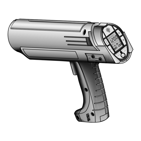
Page 16: Your Portable Infrared Thermometer
Figure 2-3 shows the features of the portable infrared thermometer. Sighting Scope Control Panel and Display Trigger (2-stage) Digital/Analog Output DC Input for AC Adaptor Battery Access Tripod Mount Fitting Figure 2-3: Features Raynger 3i Series Operator’s Manual info@Raytek-Direct.com 1.888.475.5235... - Page 17 • Analog Output—Connects the instrument to analog recording/printing devices such as chart recorders and printers. • Digital Output—An RS232 interface to connect the instrument to a computer or directly to a printer’s RS232 port. • DC In—AC adaptor connection. Raynger 3i Series Operator’s Manual info@Raytek-Direct.com 1.888.475.5235...
-
Page 18: Operation And Controls
Remove the batteries if the unit is not used for long periods of time. 220 V AC adaptors must have DIN VDE 0551 approval to be used with IEC Class 2 laser units. Raynger 3i Series Operator’s Manual info@Raytek-Direct.com 1.888.475.5235... -
Page 19: Control Panel And Display
Low battery icon Mode display RECALL ACTIVATE MODE ACTIVATE Emissivity display • • • • MODE LOCK RECALL LOCK Laser on/off LED LASER Mode value display Figure 2-4: The Control Panel and Display Raynger 3i Series Operator’s Manual info@Raytek-Direct.com 1.888.475.5235... - Page 20 4.3 V, the laser will automatically turn off. Also, if the unit is in the LOCK mode, the laser will go off when the trigger is released. Temperature display—Shows the current temperature (while the trigger is pulled) or the last temperature measured (when the RECALL button is pressed). Raynger 3i Series Operator’s Manual info@Raytek-Direct.com 1.888.475.5235...
- Page 21 Trigger lock icon—The small padlock is the trigger lock icon and is activated when LOCK is pressed while the trigger is pulled. To unlock the trigger, simply press the LOCK button again. Raynger 3i Series Operator’s Manual info@Raytek-Direct.com 1.888.475.5235...
-
Page 22: Control System
LASER • Trigger released LASER • Pull or lock trigger LASER LASER • Press RECALL • Press LOG (RCL icon activated) (LOG icon actuated) LOG Loop RECALL Loop Figure 2-5: Control Loops 2-10 Raynger 3i Series Operator’s Manual info@Raytek-Direct.com 1.888.475.5235... -
Page 23: Control Loops
For the short wavelength units (e.g., 2 µm and below)—Avoid taking temperature measurements in bright sunlight. High levels of ambient light may produce apparently valid high-temperature readings when no target is in the thermometer’s field-of-view. Raynger 3i Series Operator’s Manual 2-11 info@Raytek-Direct.com 1.888.475.5235... -
Page 24: Run Loop-To Measure Temperature
To take a measurement, do the following: 1. Point the instrument at the target. 2. Pull the trigger (press the RUN/LOG button, if necessary, so that the LOG icon is not activated). 2-12 Raynger 3i Series Operator’s Manual info@Raytek-Direct.com 1.888.475.5235... - Page 25 RUN loop, the instrument is reset to its RUN loop factory default settings (stored data is unaffected). The instrument will “beep” after reinstalling the default settings. Section 3.6 lists default setting for each model as well as non-model-specific default set- tings and range values. Raynger 3i Series Operator’s Manual 2-13 info@Raytek-Direct.com 1.888.475.5235...
-
Page 26: Log Loop-To Measure And Store Temperature
MODE button and use the buttons . 4. Press the laser button to activate the laser (if equipped with laser sighting). 5. Carefully aim using the laser or scope. 6. Read the temperature from the display. 2-14 Raynger 3i Series Operator’s Manual info@Raytek-Direct.com 1.888.475.5235... - Page 27 LOG loop factory default settings. The instrument will “beep” after reinstalling the default settings. Section 3.6 lists default setting for each model as well as non-model-specific default settings and range values. Raynger 3i Series Operator’s Manual 2-15 info@Raytek-Direct.com 1.888.475.5235...
-
Page 28: Recall Loop-To Recall Measured Temperature
If the display goes out, press the Recall button again AVG Mode DIF Mode to continue the Recall function TRIGGER BUTTON LOOP ICON Released & Unlocked RECALL & RUN Figure 2-8: RECALL Loop–Recalling RUN Values 2-16 Raynger 3i Series Operator’s Manual info@Raytek-Direct.com 1.888.475.5235... -
Page 29: Recall Values From Log
MAX modes. number again, if display goes out, displays show to continue Recall function all zeros. TRIGGER BUTTON LOOP ICONS Released & Unlocked RECALL & LOG Figure 2-9: RECALL Loop–Recalling LOG Values Raynger 3i Series Operator’s Manual 2-17 info@Raytek-Direct.com 1.888.475.5235... - Page 30 RECALL contains two modes: LOC (location) and MAX (as shown in Figure 2-9). In RECALL, the stored temperature and emissivity setting along with either the location number or MAX temperature can be displayed for each of the 100 LOG locations. 2-18 Raynger 3i Series Operator’s Manual info@Raytek-Direct.com 1.888.475.5235...
-
Page 31: Setup Loop-To Setup And Activate Alarms And Features
Temperature (T between DIG or ANA on or off with the DIG/ANA Mode TAM Mode ACTIVATE Button TRIGGER BUTTON LOOP ICON Released & Unlocked SET & RUN Figure 2-10: SETUP Loop–RUN Values Raynger 3i Series Operator’s Manual 2-19 info@Raytek-Direct.com 1.888.475.5235... - Page 32 Step 7 below. Release the trigger. 5. Press the SET button (do not pull the trigger) to enter the Setup mode 6. Press the MODE button until TAM shows in the mode function indicator. 2-20 Raynger 3i Series Operator’s Manual info@Raytek-Direct.com 1.888.475.5235...
-
Page 33: Setup Values For Log
2. Press the SET button. The SET icon will be activated. 3. Press the RUN/LOG button, if necessary, so that the LOG icon is activated. 4. Press the buttons to select the LOG location number (LOC mode). Raynger 3i Series Operator’s Manual 2-21 info@Raytek-Direct.com 1.888.475.5235... -
Page 34: Using A Tripod
LOCK button. Note that battery life is shortened by continuous use. If you plan to monitor tempera- tures over long intervals, you should connect an AC adaptor to the DC IN connector. 2-22 Raynger 3i Series Operator’s Manual info@Raytek-Direct.com 1.888.475.5235... -
Page 35: Data Outputs
Data Format: 8 bits, 1 stop bit, no parity • Analog: 1 mV/° (°C or °F) for all models except the 1M 1 mV/°C or 0.5 mV/°F for the 1M Analog RS232 RS232 Figure 2-12: Data Outputs Raynger 3i Series Operator’s Manual 2-23 info@Raytek-Direct.com 1.888.475.5235... -
Page 36: Digital Output
0 . 95 0090 <CR> <LF> 0081 0 . 95 –018 <CR> <LF> 0081 0 . 95 –018 <CR> <LF> 0027 0 . 95 –028 <CR> <LF> 0027 1 . 00 –028 <CR> <LF> 2-24 Raynger 3i Series Operator’s Manual info@Raytek-Direct.com 1.888.475.5235... -
Page 37: Data Output-Set Loop
°F, and DOI = 3600 seconds. (The <CR> and <LF> do not print; these denote the carriage return and line feed.) Note: DOI does not apply to the SETUP mode. Raynger 3i Series Operator’s Manual 2-25 info@Raytek-Direct.com 1.888.475.5235... -
Page 38: Data Output-Log Run Loop
99, so these locations were not sent out. There will be a pause in printing between locations 1 and 6 and between locations 7 and 100 because the unit is searching through the locations sequentially for stored data. DOI does not apply to the LOG mode. 2-26 Raynger 3i Series Operator’s Manual info@Raytek-Direct.com 1.888.475.5235... -
Page 39: Data Output-Log Setup Loop
3. For Locations 3, 4, 5, 6, and 7, HAL is not activated and is 85°F. 4. For Location 8, HAL is activated and is 65°F. Note: DOI does not apply to the LOG SETUP mode. Raynger 3i Series Operator’s Manual 2-27 info@Raytek-Direct.com 1.888.475.5235... -
Page 40: Analog Output
The analog output represents the current temperature of the object being measured, regardless of the mode used. If T compensation is activated, the analog output will be representative of the compensated temperature values. 2-28 Raynger 3i Series Operator’s Manual info@Raytek-Direct.com 1.888.475.5235... -
Page 41: Sighting Systems
Note: The laser turns off automatically when the trigger is released. It cannot be locked on when the trigger is locked. It cannot be turned on in the Recall and Setup loops. Raynger 3i Series Operator’s Manual 2-29 info@Raytek-Direct.com 1.888.475.5235... - Page 42 RAYONNEMENT LASER RAYO LASER NE PAS EXPOSER L'OEIL NO FIJAR LA VISTA <1mW/630–670nm AU RAYON LASER EN EL RAYO IEC 825/93 LASER DE CLASSE 2 LASER CLASE 2 Figure 2-13: Laser Labels 2-30 Raynger 3i Series Operator’s Manual info@Raytek-Direct.com 1.888.475.5235...
-
Page 43: Single Laser Sighting
DISTANCE: SENSOR TO OBJECT (m) IR Spot Diameter at Lens = 23 mm (0.9 in) Laser Diameter at Lens = 40 mm (1.6 in) LASER Figure 2-15: Dual Laser and IR Spot Diameters Raynger 3i Series Operator’s Manual 2-31 info@Raytek-Direct.com 1.888.475.5235... -
Page 44: Crossed Laser Sighting
A for the focus point distance for your model). The outer reticle indicates an area greater than or equal to the area that is measured at all other distances. Figure 2-17: Scope Sighting 2-32 Raynger 3i Series Operator’s Manual info@Raytek-Direct.com 1.888.475.5235... - Page 45 The scope has one reticle and it indicates the target area that is measured at the focus point (see Appendix A for the focus point distance of your model). See section 2.7.4 and Figure 2-17 for further details on the scope. Figure 2-18: Scope with Laser Sighting Raynger 3i Series Operator’s Manual 2-33 info@Raytek-Direct.com 1.888.475.5235...
- Page 46 2-34 Raynger 3i Series Operator’s Manual info@Raytek-Direct.com 1.888.475.5235...
-
Page 47: Specifications
The instrument may measure temperature a few degrees below the minimum and above the maximum specified temperature range. Note: Hi Alarm, Lo Alarm, and T. Ambient ranges are the same as measurement ranges in Table 3-1. Raynger 3i Series Operator’s Manual info@Raytek-Direct.com 1.888.475.5235... -
Page 48: Operational
DOI (Digital 1 to 9999 seconds Output Interval) Analog Output 1°C or 1°F Resolution LOG Locations 1 to 100 Response Time 700 msec 550 msec 550 msec 700 msec 700 msec (95% response) Raynger 3i Series Operator’s Manual info@Raytek-Direct.com 1.888.475.5235... -
Page 49: Electrical
Digital Output RS232, 9600 baud Digital Output Same as Measurement Range in Table 3-1 Range Power Four (4) AA alkaline or rechargeable batteries or 6 to 9 volt, 200 mA, DC power supply Requirements Raynger 3i Series Operator’s Manual info@Raytek-Direct.com 1.888.475.5235... -
Page 50: Environmental
257 mm (10.1 in) L 71 mm (2.8 in) W 71 mm (2.8 in) W 71 mm (2.8 in) W Weight 794 g (1.75 lbs) 1000 g (2.21 lbs) 1000 g (2.21 lbs) Raynger 3i Series Operator’s Manual info@Raytek-Direct.com 1.888.475.5235... -
Page 51: Default Values
LOG Location LOG Data–All Locations Current Temperature 0 degrees C, or 0 degrees F MAX Temperature 0 degrees C, or 0 degrees F Hi Alarm Value See Table 3-6 Hi Alarm State Emissivity 0.95 Raynger 3i Series Operator’s Manual info@Raytek-Direct.com 1.888.475.5235... -
Page 52: Regulatory
The appropriate regulatory approvals and certificates have been issued as follows: • FDA Class II Laser Certification • FDA Class IIIa Laser Certification • IEC Class 2 Laser Certification • IEC801-3 (EN50082) for EMI susceptibility Raynger 3i Series Operator’s Manual info@Raytek-Direct.com 1.888.475.5235... -
Page 53: Maintenance
Do not wipe the surface dry, as this may scratch the surface. CAUTION Do not use any ammonia, or cleaners with ammonia, bleach, acids, or strong bases. This can cause severe damage to the front window. Raynger 3i Series Operator’s Manual info@Raytek-Direct.com 1.888.475.5235... -
Page 54: Cleaning The Housing
Wipe with a damp sponge or soft rag. Use a soft rag to gently wipe the dis- play. LASER MAINTENANCE If the laser (laser models only) does not operate properly, call your infrared ther- mometer supplier. DO NOT open the instrument’s main housing. Raynger 3i Series Operator’s Manual info@Raytek-Direct.com 1.888.475.5235... -
Page 55: Appendix A: Optical
S f = Larger known spot size D x = Distance to unknown spot D n = Distance to smaller known spot D f = Distance to larger known spot Figure A-1: How to Read the Optical Charts Raynger 3i Series Operator’s Manual info@Raytek-Direct.com 1.888.475.5235... -
Page 56: Optical Charts
IR Spot Diameter at Lens = 23 mm (0.9 in) 25 mm @ 4.6 m DISTANCE: SENSOR TO OBJECT IN METERS FOCUS POINT D:S = 180:1 FAR FIELD D:S = 140:1 IR Spot Diameter at Lens = 7 mm (0.3 in) Raynger 3i Series Operator’s Manual info@Raytek-Direct.com 1.888.475.5235... - Page 57 FOCUS POINT D:S = 25:1 @15 m (50 ft) FAR FIELD D:S = 23:1 IR Spot Diameter at Lens = 23 mm (0.9 in) IR Beam Profile Laser Diameter at Lens = 40 mm (1.6 in) Laser Profile Raynger 3i Series Operator’s Manual info@Raytek-Direct.com 1.888.475.5235...
- Page 58 Raynger 3i Series Operator’s Manual info@Raytek-Direct.com 1.888.475.5235...
-
Page 59: Appendix B: Object Emissivity
0.93. Finally, measure an adjacent area on the object and adjust the emissivity setting until you reach the same temperature. This is the correct emissivity for the measured material. Raynger 3i Series Operator’s Manual info@Raytek-Direct.com 1.888.475.5235... -
Page 60: Typical Emissivity Values
Electrical Terminal Blocks n.r. n.r. Gold 0.01-0.1 n.r. Haynes Alloy 0.5-0.9 0.6-0.9 0.3-0.8 Inconel Oxidized 0.4-0.9 0.6-0.9 0.7-0.95 Sandblasted 0.3-0.4 0.3-0.6 0.3-0.6 Electropolished 0.2-0.5 0.25 0.15 n.r. = not recommended Continued on next page Raynger 3i Series Operator’s Manual info@Raytek-Direct.com 1.888.475.5235... - Page 61 Tin (Unoxidized) 0.25 0.1-0.3 n.r. Titanium Polished 0.5-0.75 0.3-0.5 n.r. Oxidized n.r. 0.6-0.8 0.5-0.6 Tungsten n.r. 0.1-0.6 n.r. Polished 0.35-0.4 0.1-0.3 n.r. Zinc Oxidized 0.15 Polished 0.05 n.r. Material Emissivity n.r. = not recommended Raynger 3i Series Operator’s Manual info@Raytek-Direct.com 1.888.475.5235...
- Page 62 5. Hold instrument perpendicular to surface whenever emissivity is less than 0.9. In all cases, do not exceed angles more than 30 degrees from incidence. 6. For 1M and 2M models, avoid measurements in high ambient light conditions (see Page 2-11). Raynger 3i Series Operator’s Manual info@Raytek-Direct.com 1.888.475.5235...
-
Page 63: Appendix C: Troubleshooting
RS-232 output are sent the -U- failsafe code. The mode display and RS- 232 ouput are sent either the correct MAX temperature or the -U- failsafe code. The analog output is sent the minimum temperature for your model. Raynger 3i Series Operator’s Manual info@Raytek-Direct.com 1.888.475.5235... - Page 64 Note: On laser models, if the internal temperature is less than 0°C (32°F) or greater than 45°C (113°F), the laser will automatically turn off. The laser will also automatically turn off if the battery is too low (when the low battery icon displays). Raynger 3i Series Operator’s Manual info@Raytek-Direct.com 1.888.475.5235...
- Page 65 To clear the instrument’s system, release then press the trigger. If this does not clear the problem, slide the battery door off then back on. (This disconnects the battery power.) Raynger 3i Series Operator’s Manual info@Raytek-Direct.com 1.888.475.5235...
- Page 66 Raynger 3i Series Operator’s Manual info@Raytek-Direct.com 1.888.475.5235...
-
Page 67: Appendix D: Options And Accessories
A full range of options for various applications and environments is available. Options are factory installed and must be ordered with base model units. The follow- ing options are available: • NIST certification Raynger 3i Series Operator’s Manual info@Raytek-Direct.com 1.888.475.5235... - Page 68 Raynger 3i Series Operator’s Manual info@Raytek-Direct.com 1.888.475.5235...
-
Page 69: Appendix E: Traceability Of Instrument Calibration
Certified RTD Certified RTD Standard Instrumentation & NIST Instrumentation Calibrated Radiation Transfer Standard Instrument Calibration Source Measured Calibration Source (Blackbody) Source (Blackbody) Emissivity < 1 Emissivity Emissivity Calibrated Product Figure E-1: Traceability Flowchart Raynger 3i Series Operator’s Manual info@Raytek-Direct.com 1.888.475.5235... - Page 70 Raynger 3i Series Operator’s Manual info@Raytek-Direct.com 1.888.475.5235...
-
Page 71: Appendix F: Ce Conformity For The European Community
The instrument’s average error in this frequency range for the three orientations is 3.1° C at an electric field strength of 3 V/m. At some frequencies the instrument may not meet its stated accuracy. Raynger 3i Series Operator’s Manual info@Raytek-Direct.com 1.888.475.5235... - Page 72 Raynger 3i Series Operator’s Manual info@Raytek-Direct.com 1.888.475.5235...
-
Page 73: Glossary Of Terms
AVG is a weighted average of all read- the last series of measured temperatures dis- ings taken since the trigger was pulled. plays. Raynger 3i Series Operator's Manual Glossary-1 info@Raytek-Direct.com 1.888.475.5235... - Page 74 (air conditioners, power Community. tools, refrigeration systems, etc.). IEEE-488 °F (Fahrenheit) A communications format standard. See dig- Temperature scale where °F = (°C x 1.8) + 32 ital data bus. = °R - 459.67. Glossary-2 Raynger 3i Series Operator's Manual info@Raytek-Direct.com 1.888.475.5235...
- Page 75 Single or dual lasers are used in some units the output (display or analog) expressed in for aiming and/or locating the optimum tem- °F or °C. perature measurement point. Raynger 3i Series Operator's Manual Glossary-3 info@Raytek-Direct.com 1.888.475.5235...
- Page 76 (per the ture (given a known emissivity) from mea- ASTM standard test method E 1256-88). The surement of either visible or infrared radia- specification for Raytek instruments also tion from that object. includes the average time required for soft- ware computations.
- Page 77 Spectral Filter An optical element used to restrict the spec- flows from objects of higher temperature to tral band of energy reaching an instrument’s objects of lower temperature. detector. Raynger 3i Series Operator's Manual Glossary-5 info@Raytek-Direct.com 1.888.475.5235...
- Page 78 D tungsten-3% rhenium/tungsten-25% rhenium Thermopile An arrangement of thermocouples in series such that the alternate junctions are at the measuring temperature and at the reference temperature. This arrangement increases the thermoelectric voltage. Glossary-6 Raynger 3i Series Operator's Manual info@Raytek-Direct.com 1.888.475.5235...
Need help?
Do you have a question about the RAYNGER 3i LTDL2 and is the answer not in the manual?
Questions and answers