Table of Contents
Advertisement
Instruction Manual and Replacement Parts List
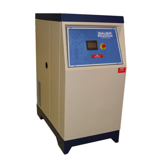
Mini Verticus
High Pressure Gas Compressor Units
G 120 II V
April 4, 2013
BAUER Compressors, Inc.
1328 Azalea Garden Road
Norfolk, Virginia 23502-1944
1st Edition, Rev. 0 Chg. 2
© Bauer Compressors, Inc.
MNL-126509
Phone: (757) 855-6006
Fax: (757) 855-6224
www.bauercomp.com
Advertisement
Table of Contents

Related Manuals for Bauer Mini Verticus


Summary of Contents for Bauer Mini Verticus
- Page 1 Mini Verticus High Pressure Gas Compressor Units G 120 II V April 4, 2013 1st Edition, Rev. 0 Chg. 2 MNL-126509 © Bauer Compressors, Inc. BAUER Compressors, Inc. Phone: (757) 855-6006 1328 Azalea Garden Road Fax: (757) 855-6224 Norfolk, Virginia 23502-1944...
- Page 2 G 120 II V This information is believed to be accurate by Bauer Compressors, Inc., as of it’s date of publication, but Bauer offers NO WARRANTY regarding the accuracy, or continuing accuracy, of the information set forth herein. Bauer shall not be liable for inaccuracies in, or consequences resulting from, your use of this infor- mation.
- Page 3 MNL-126509 Table of Contents CHAPTER 1: - - - - - - - - - - - - - - - - - - - - - INTRODUCTION HOW TO USE THIS MANUAL............................1 1.1.1 Manual Safety Notices ............................... 1 HOW TO USE THE REPLACEMENT PARTS LIST ....................
- Page 4 G 120 II V 3.1.6 Inter-stage Separator.................................20 3.1.6.1 Maintenance..................................21 3.1.7 Cooling .....................................21 3.1.7.1 General..................................21 3.1.8 Valves and Heads ................................21 3.1.8.1 Functional Description..............................21 3.1.8.2 General Instructions for Changing the Valves......................22 3.1.8.3 Changing the IK120 II C & G, 1st Stage Valve ......................23 3.1.8.4 Removing the IK120 II C &...
- Page 5 MNL-126509 4.2.2.3 Cartridge ..................................65 4.2.2.4 Cartridge Handling ............................... 65 4.2.2.5 Condensate Drain Valve ............................... 65 4.2.2.6 Check Valves ................................65 4.2.2.7 Bleed Valve .................................. 66 4.2.2.8 Pressure Maintaining Valve............................66 4.2.2.9 Safety Valve.................................. 66 MAINTENANCE................................66 4.3.1 Oil and Water Separator ..............................66 4.3.2 Cartridge Replacement..............................
- Page 6 G 120 II V PLC INPUTS AND OUTPUTS ............................84 6.6.1 Analog Inputs to the PLC..............................85 WIRING HARNESS LAYOUT ............................86 REPLACEMENT PARTS LIST ............................88 PARTS LIST FOR MODELS WITH A 5 HORSEPOWER MOTOR.................96 6.10 PARTS LIST FOR MODELS WITH A 7½ HORSEPOWER MOTOR..............97 6.11 PARTS LIST FOR MODELS WITH A 10 HORSEPOWER MOTOR...............98 6.12 PARTS LIST FOR MODELS WITH A 15 HORSEPOWER MOTOR...............99 6.13 PARTS LIST FOR MODELS WITH A 20 HORSEPOWER MOTOR..............100...
- Page 7 MNL-126509 8.3.6 Reactivating the Compressor Unit ..........................117 REPRODUCIBLE FORMS ............................118 8.4.1 Scheduled Maintenance Form ............................118 8.4.2 Air Purification Cartridge Operating Hours........................121 8.4.3 Record of Operating Hours ............................122 REFERENCE DATA............................... 123 8.5.1 Tightening Torque Values.............................. 123 8.5.2 Torque Sequence Diagrams ............................
- Page 8 G 120 II V List of Figures CHAPTER 1:- - - - - - - - - - - - - - - - - - - - - INTRODUCTION Figure 1-1 Compressor Identification Label ..........................2 CHAPTER 2:- - - - OPERATING INSTRUCTIONS; MAPLE SYSTEM Figure 2-1 MNR-0053................................5 Figure 2-2...
- Page 9 MNL-126509 Figure 3-29 Inlet Assembly............................... 46 Figure 3-30 Automatic Condensate Drain ..........................49 Figure 3-31 ACD Operation Diagrams ............................. 50 Figure 3-32 ACD System................................52 Figure 3-33 ACD Valve and Manifold Assembly ........................53 Figure 3-34 Condensate Collector............................. 54 Figure 3-35 Condensate Collector.............................
- Page 10 G 120 II V Figure 6-17 Electrical Panel, Interior, 60 Hz ..........................92 Figure 6-18 Electrical Panel, Interior, 50 Hz ..........................94 CHAPTER 7:- - - - - - - - - - - - - - - - -INDICATORS & VALVES Figure 7-1 Indicators ................................101 Figure 7-1...
-
Page 11: How To Use This Manual
OEM Manuals or additional Bauer Manuals. While every effort is made to ensure the accuracy of the information contained in this manual, Bauer Compressors, Inc. will not, under any circumstances be held accountable for any inaccuracies or the con- sequences thereof. -
Page 12: How To Use The Replacement Parts List
02/2013 Part Number VAL-0500 Part Description Valve Part Quantity Required Compressor Identification Label Figure 1-1 BAUER COMPRESSORS, INC. NORFOLK, VA 23502 U.S.A. (757) 855-6006 MODEL NO. BLOCK NO. SERIAL NO. QUANTITY MFG. DATE Page 2 1st Edition, Rev. 0 Chg. 2... -
Page 13: How To Use The Appendix
MNL-126509 ^ WARNING The use of repair parts other than those included in the Bauer Replacement Parts Lists may create unsafe conditions over which Bauer has no control. Such unsafe conditions can lead to accidents that may be life- threatening, cause substantial bodily injury, and/or result in damage to the equipment. Therefore, Bauer Compressors, Inc. -
Page 14: Unit Specifications
7.5 Hp ODP 10.5, 10, 9.5 MTR-0208 1.4.0.2 Purification System Applicability The G 120 II V is standardly equipped with the Bauer P1 or Oil Removal Filtration System. 1.4.0.3 Pressure Switch Settings 1.4.0.3.1 Inlet Pressure Switch Settings Low Inlet Pressure 0.0 psig... -
Page 15: Description
MNL-126509 CHAPTER 2: OPERATING INSTRUCTIONS; MAPLE SYSTEM 2.1 Description The following instructions apply to units that use the Maple System touchscreen operator interface, MNR-0053 with program 31L MNR-0053 Figure 2-1 SECURUS The Electrical Panel Assembly will provide logical control and safety shutdowns for the compressor equipment. -
Page 16: Operator Interface
G 120 II V 2.1.2 Operator Interface The Operator Interface is a 4.3 inch, 256 color, 8 bit LCD with touchscreen operation. The Operator Interface is the input/output device for normal operation of the compressor unit. The compressor system is ready and able to operate after the Emergency Stop Switch is pulled out and the red “COM” status light illuminates. -
Page 17: Main Menu Screen
MNL-126509 5. The ON and OFF buttons control the compressor. These buttons should be used for normal starting and stopping of the compressor. In an emergency the Emergency Stop button should be used. 6. This X button closes the Run screen and goes to the main menu screen. The compressor may still be operating when returning to the main menu screen. -
Page 18: Alarms History
G 120 II V 2.1.2.2.2 Alarms History This button displays the history of alarms. The date of the alarm history can be changed with the drop down arrow or the forward and backward arrows adjacent to the date. To return to the Main Menu screen touch the X in the upper right corner. -
Page 19: Configuration
MNL-126509 Login Screens Figure 2-6 To change the user level press the “USER” button, select the desired user, and press “OK”. Then press the button below the words “Enter Password” and press the password numbers on the keypad. After entering the proper password press “ENT”... -
Page 20: Parameters
G 120 II V 2.1.2.2.7 Parameters This button takes the user to the parameters screens. There are a total of 9 screens. These parameters are set at the factory for each specific unit. Changing these parameters will change how the unit operates, so only users 2 and 3 are allowed to change them. -
Page 21: To Start Unit
MNL-126509 2.2.2 To Start Unit. Press the green START Button on the Run Screen. (See Figure 2-3) If the pressure in the system is lower than the set “Start Pressure”, the drive motor will start up powering the compressor. If the system’s pressure is higher than the set “Start Pressure” or when the air pressure has increased to the set “Operating Pressure”, the drive motor will automatically shutdown. - Page 22 G 120 II V Table 2-1: Calendar Maintenance Interval Tasks Task Monthly Annually Every Two Years Calibrate CO Monitor Check Oil Level Check Final Pressure Shutdown Check Automatic Condensate Drain Check V-belt Service Intake Filter Check all connections for leaks Inspect Compressor Valves Check all fasteners for tightness Change Synthetic Oil...
- Page 23 MNL-126509 Table 2-2: Operating Hours Maintenance Interval Tasks 1,000 2,000 3,000 Task Hours Hours Hours Hours Hours Check Oil Level Check Final Pressure Shutdown Check Automatic Condensate Drain Check V-belt Service Intake Filter Check all connections for leaks Check fasteners for tightness Inspect Compressor Valves Change Synthetic Oil Replace Oil Filter...
-
Page 24: Screen Flow
G 120 II V 2.3 Screen Flow Operator Interface Screen Flow Figure 2-8 Page 14 1st Edition, Rev. 0 Chg. 2... -
Page 25: Maintenance And Parts
MNL-126509 CHAPTER 3: IK120 II C & G 3.1 Maintenance and Parts 3.1.1 Description The IK120 II C & G compressors are used to compress gases up to a maximum of 5,000 psi. Both com- pressors are three cylinder, three stage air cooled, oil lubricated reciprocating compressors. The 3rd stage cylinder is lubricated by means of the forced feed lubrication system, while the other cylinders are splash lubricated. -
Page 26: Air Flow Diagram
G 120 II V Air Flow Diagram Figure 3-2 Purification System 1. Intake Manifold 8. 1st Stage Safety Valve 2. 1st Stage Cylinder 9. 2nd Stage Safety Valve 3. 2nd Stage Cylinder 10. 3rd Stage Safety Valve (Final Pressure) 4. 3rd Stage Cylinder 11. -
Page 27: Compressor Lubrication
MNL-126509 Lubrication Oil Circuit Figure 3-3 1. Oil Pump 4. Guide Piston 2. Oil Filter 5. Oil Sight Glass 3. Minimum Pressure Valve 3.1.4 Compressor Lubrication 3.1.4.1 Description Refer to Figure 3-3. The compressor is provided with forced-feed lubrication. The oil pressure is pro- duced by a low speed gear pump (1). -
Page 28: Oil Change Interval
G 120 II V lubrication. Oil level must also not exceed the maximum mark as this will cause excessive lubrication of the compressor and may result in a carbon buildup on the valves. Oil Sight Glass Oil Filler Cap Figure 3-4 Figure 3-5 Removing the Oil Filter Cover Replacing the Oil Filter... -
Page 29: Oil Change
MNL-126509 3.1.4.4 Oil Change 1. Run the compressor until it is warm then shut it down. 2. (See Figure 3-5). Remove the cap (1) from the oil filler neck. 3. Drain oil while it is still warm by means of the oil drain plug. ^ CAUTION Replace the oil filter every oil change. -
Page 30: Inter-Stage Separator
G 120 II V 3.1.6 Inter-stage Separator An inter-stage separator is mounted on the compressor block. This separator is designed to remove oil and water which accumulates due to the cooling of the medium after the compression process. Separation is achieved by means of centrifugal action provided by a vortex plate (1). Inter-stage Separator Figure 3-8 1. -
Page 31: Maintenance
MNL-126509 3.1.6.1 Maintenance The inter-stage Separator requires no maintenance. 3.1.7 Cooling 3.1.7.1 General The cylinders of the compressor, the inter-stage coolers and the after cooler are air cooled. For this pur- pose the compressor is equipped with a fanwheel which draws the cooling air through the unit. The fan- wheel is driven by the drive motor V-belt and is also used as the compressor flywheel. -
Page 32: General Instructions For Changing The Valves
G 120 II V IK120II C & G, 1st Stage Valve Figure 3-10 TOP VIEW Intake Side Pressure Side 3.1.8.2 General Instructions for Changing the Valves • Always replace valves as a complete set. • Carefully clean dirty valves. Never use a sharp tool for this purpose. Soak the valves in Varsol and clean with a soft brush. -
Page 33: Changing The Ik120 Ii C & G, 1St Stage Valve
MNL-126509 3.1.8.3 Changing the IK120 II C & G, 1st Stage Valve The intake and pressure valve of the IK120 II C & G 1st stage are in a combined plate valve under the valve head. Refer to Figure 3-11 IK120 II C 1st Stage Valve Head and Plate Valve Figure 3-11 1. -
Page 34: Removing The Ik120 Ii C & G, 2Nd Stage Valves
G 120 II V 3.1.8.4 Removing the IK120 II C & G, 2nd Stage Valves. IK120 II C & G, 2nd Stage Valve Head and Valves Figure 3-12 1. Cap Nut 5. Pressure Valve Insert 2. Stud 6. Intake Valve 3. -
Page 35: Reassembling The Valves Of The 2Nd Stage
MNL-126509 8. Remove the Pressure Plug (3) and take out the valve parts. 9. Clean the Intake Valve and Pressure Valve Assembly, preferably with an ultrasonic cleaner and check for wear and damage. 10. Valve Seats and Valves must not show any signs of wear or damage. Replace damaged or worn parts. -
Page 36: Removing The Ik120 Ii C & G, 3Rd Stage Valves
G 120 II V 8. Replace the Valve Head (7) on the cylinder and secure it with the Screws (8). 9. Reconnect the intake and pressure lines. 3.1.8.6 Removing the IK120 II C & G, 3rd Stage Valves IK120 II C & G, 3rd Stage Valve Head and Valves Figure 3-15 1. -
Page 37: Reassembling The Valves Of The 3Rd Stage
MNL-126509 Removing the 3rd Stage Pressure Valve Figure 3-16 3.1.8.7 Reassembling the Valves of the 3rd Stage 1. Replace the Intake Valve (1) using the special valve tool to tighten it. 2. Check the intake valve functions correctly by blowing compressed air through the valve in the direction of flow. -
Page 38: Replacement Parts List
G 120 II V 3.1.9 Replacement Parts List Crankcase Assembly Figure 3-17 # KIT Qty Part No. Description Notes 076743 Crankcase assembly with accessories, driving gear … 76740 Crankcase … 083399 Crankshaft, complete IK120 II -G/C … N2638 Roller Bearing …... - Page 39 MNL-126509 Crankcase Assembly Figure 3-17 (cont.) # KIT Qty Part No. Description Notes 13 … 73830 Oil Filling Pipe 14 … N4776 O-ring 15 … N1506 Hex Head Bolt 16 … Washer 17 … N4261 Gasket 18 … N2796 Plug 19 …...
- Page 40 G 120 II V Piston and Cylinder, 1st Stage Figure 3-18 # KIT Qty Part No. Description Notes 080826 Piston and Cylinder Assembly IK120 II C … 80734 Cylinder, IK120 II C 88 mm N4654 O-ring … 069975 Piston Assembly, IK120 II C 88 mm (includes #4-6) …...
- Page 41 MNL-126509 Piston and Cylinder, 2nd Stage Figure 3-19 # KIT Qty Part No. Description Notes 85948 Piston and Cylinder Assembly 2nd Stage … 62477 Cylinder N7063 O-ring … 83404 Guide Cylinder N2640 O-ring NUT-0119 Self Locking Hex Nut … WAS-0021 Washer …...
- Page 42 G 120 II V Piston and Cylinder, 3rd Stage Figure 3-20 # KIT Qty Part No. Description Notes 83400 Piston and Cylinder Assembly 3rd Stage 078043 Piston and Sleeve Assembly See Figure 3-21 … 82480 Cylinder N7063 O-ring … 83404 Guide Cylinder N2640...
- Page 43 MNL-126509 Piston and Sleeve, 3rd Stage Figure 3-21 # KIT Qty Part No. Description Notes 078043 Piston and Sleeve Assembly … † — Piston Available only with 078043 N23755 O-ring … † — Piston Liner Available only with 078043 …...
- Page 44 G 120 II V 1st Stage Valve Head and Valve, IK120 II C & G Figure 3-22 # KIT Qty Part No. Description Notes 80727 Valve Head, 1st Stage IK120 II C & G … N26531 Plate Valve IK120 II C & G …...
- Page 45 This page is inserted to provide proper page sequencing...
- Page 46 G 120 II V 2nd Stage Valves and Valve Head Figure 3-23 # KIT Qty Part No. Description Notes 69955 Valve Head, 2nd Stage … 14123 Valve Head 012841 Intake Valve Assembly Items 3 - 7 … † Intake Valve Body Available only with 012841 …...
- Page 47 MNL-126509 2nd Stage Valves and Valve Head Figure 3-23 (cont.) # KIT Qty Part No. Description Notes 14 a.. N3521 O-ring 15 … 14332 Spring Washer 16 … 14124 Coupling 17 .b. 71064 Stud 18 a.. N3625 Gasket 19 … Cap Nut 20 …...
- Page 48 G 120 II V 3rd Stage Valves and Valve Head Figure 3-24 # KIT Qty Part No. Description Notes 082096 Valve Head Assembly, 3rd Stage 081409 Intake Valve … 082087 Valve Head N2789 O-ring 014121 Pressure Valve … 82086 Valve Head Cover N124608 Stud...
- Page 49 MNL-126509 Flywheel Figure 3-25 Item Qty Part No. Description Notes 82552 Flywheel Assembly N1386 Shaft Key 82553 80975 Washer N176 Split Washer N26666 Bolt 82496 Flywheel N108 Spring Washer N19548 Allen Screw April 4, 2013 Page 39...
- Page 50 G 120 II V Inter-Stage Separator Figure 3-26 # KIT Qty Part No. Description Notes 081799 inter-stage Separator Assembly … 81148 Plate … 81643 Hollow Screw … 76613 Inset Assembly N3556 O-ring … 13937 Knurled Ring … N1316 Gasket …...
- Page 51 This page is inserted to provide proper page sequencing...
- Page 52 G 120 II V Lubrication System Assembly Figure 3-27 # KIT Qty Part No. Description Notes 83417 Lubricating System Items 1 - 14 … 77885 Oil Filter Cover … N4058 O-ring … N25327 O-ring … 77774 Rubber Gasket … N25326 Filter Element …...
- Page 53 MNL-126509 Lubrication System Assembly Figure 3-27 (cont.) # KIT Qty Part No. Description Notes 14 … 81050 Regulating Valve 15 … N1316 Gasket 16 … Plug 17 … 83420 Connecting Tube Assembly 18 … N20237 Male Connector April 4, 2013 Page 43...
- Page 54 G 120 II V Cooling System Figure 3-28 # KIT Qty Part No. Description Notes 83456 IK120 II C & G Cooling System … 79486 Intercooler, 1st to 2nd Stage … 78195 Intercooler, 2nd to 3rd Stage … 070724 Aftercooler …...
- Page 55 MNL-126509 Cooling System Figure 3-28 (cont.) # KIT Qty Part No. Description Notes 15 … N3610 Screw Cap, SS 16 … N20327 T- Connector 17 … N15175 Plug 18 … N7433 Screw Cap, SS 19 … N26751 Coupling 20 … N20183 Connector 21 …...
-
Page 56: Inlet Assembly
G 120 II V Inlet Assembly Figure 3-29 INLET FROM SUPPLY COMPRESSOR INLET Item Qty Part No. Description Notes SEN-0055 Pressure Sensor 0 -30 psia, 1-11 V GAG-00011W Pressure Gauge 30 Hg - 15 psi FLR-0009 Filter, Particulate gas tight —... -
Page 57: Troubleshooting And Repair
MNL-126509 3.1.10 Troubleshooting and Repair 3.1.10.1 Troubleshooting Table Trouble Cause Remedy No oil pressure Low oil level Check oil level 1. Last stage piston worn 1. Operate compressor with 2. Last stage pressure valve final stage valve head defective removed. If oil flows con- Oil foam in crankcase tinuously out of cylinder, replace piston and sleeve. -
Page 58: Repair Instructions
G 120 II V 3.1.10.2 Repair Instructions Repair work can be carried out on the compressor block to a certain extent but a certain level of experi- ence and skill is necessary. It should be noted however that no repair should be carried out on the crank- shaft nor on the bearings and safety valves are not repaired but always replaced Page 48 1st Edition, Rev. -
Page 59: Three Stage Automatic Condensate Drain System
MNL-126509 3.2 Three Stage Automatic Condensate Drain System 3.2.1 Description The automatic condensate drain is an optional system and may not be included with your unit. The automatic condensate drain system operates electropneumatically and is comprised of the following: An electrically controlled solenoid valve An electrical timer A pneumatically operated condensate drain valve A condensate manifold... -
Page 60: Normal Operation
G 120 II V ACD Operation Diagrams Figure 3-31 Control Air Condensate Control Air Condensate Condensate Draining Normal Operation 1. Solenoid Valve 3. Oil and Water Separator 2. Intermediate Separator 4. Condensate Drain Valve 3.2.1.1 Normal Operation The normally open solenoid valve (1) controls the condensate draining of the intermediate separator (2). The normally open condensate drain valve (4) controls the condensate draining of the oil and water sepa- rator. -
Page 61: Standstill Drainage
MNL-126509 the control air closes the condensate drain valve (4). Once the valve closes, the compressor delivers to the consuming device. 3.2.1.4 Standstill Drainage At compressor shutdown, the solenoid valve (1) is de-energized and opens. This drains the condensate and relieves the pressure in the intermediate filter (2). This action in turn removes the control air form the condensate drain valve which opens and drains and relieves the pressure in the oil and water separator. -
Page 62: Acd Replacement Parts List
G 120 II V 3.2.4 ACD Replacement Parts List ACD System Figure 3-32 Item Qty Part No. Description Notes DGM-2280 3 Stage Compressor ACD Reference only N27288 Electric Coil 115 VAC N27757 Electric Coil 12 VDC N27099 Solenoid Valve PLT-0297 Blank-Off Plate MFD-0035... -
Page 63: Acd Valve And Manifold Assembly
MNL-126509 ACD Valve and Manifold Assembly Figure 3-33 Item Qty Part No. Description Notes — ACD Valve and Manifold Assembly 075169 Condensate Drain Valve Assembly PLT-0297 Blank off Plate N00638 O-ring MFD-0035 Condensate Manifold N00829 Socket Head Cap Screw N03625 Copper Gasket N02507... -
Page 64: Condensate Collector
G 120 II V 3.3 Condensate Collector During compression the water content of the air is also compressed. The resulting water is removed after each compression stage and is collected through the automatic condensate drain system. This water, additionally, has a small oil content. The separation of oil and water is not possible through simple methods;... -
Page 65: Condensate Collector Replacement Parts List
MNL-126509 3.3.1 Condensate Collector Replacement Parts List Condensate Collector Figure 3-35 Item Qty Part No. Description Notes CAP-0056 Condensate Collector Cover GKT-0065 Gasket ELM-0160 Fine Filter Element ELM-0161 Coarse Filter Element HUS-0050 Condensate Collector, Inner HUS-0060 Condensate Collector, Outer SWT-0265 Float Switch TNK-0092 Condensate Collection Tank... -
Page 66: Introduction
The purpose of all Bauer breathing air purification systems is to remove carbon monoxide, oil, water, taste and odor from the compressed air stream before final delivery. The purpose of all Bauer industrial air purification systems is to remove oil and water from the com- pressed air stream before final delivery. -
Page 67: Manual Condensate Drainage
MNL-126509 Cartridge Safety Venting P0 & P31 Safety Venting Figure 4-1 Figure 4-2 Safety Safety Vent Vent Safety Safety Vent Vent Cartridge Installed No Cartridge Installed correctly or Installed incorrectly No Cartridge or Installed Cartridge Installed Correctly Incorrectly 4.1.3 Manual Condensate Drainage The condensate must be drained from the oil and water separator before changing any cartridge, before beginning each filling procedure and in the absence of an Automatic Condensate Drain (ACD) system, every fifteen minutes during the filling procedure. -
Page 68: Purification System Dataplate
G 120 II V 4.1.4.2 Purification System Dataplate Refer to the compressor unit purification system data plate (Figure 4-3) on the compressor front to deter- mine your purification system model and specifications. 4.1.4.3 Cartridge Installation Dataplate The function performed by each chamber in the purification system is determined by the type of cartridge installed in that chamber. -
Page 69: Industrial Purification System Configurations
Each Bauer compressor block is rated to produce a standard volume of air per minute and by using this number and the air processing capability of the purification system it is possible to calculate the maxi- mum operating hours before the cartridges need to be replaced. -
Page 70: Calculating The Maximum Cartridge Operating Hours
G 120 II V is suggested that it be copied, placed in a protective folder and kept with the unit to record the adjusted operating hours. An example of how this form is used is shown in Figure 4-5. 4.1.7.1 Calculating the Maximum Cartridge Operating Hours 1. -
Page 71: Correction Factor For Cartridge Operating Hours
MNL-126509 Correction Factor for Cartridge Operating Hours Figure 4-4 0 °C 10 °C 20 °C 30 °C 40 °C 50 °C 32 °F 50 °F 68 °F 86 °F 104 °F 122 °F °C °F Correction Factor (°F - 32) x 5/9 °C x 9/5 +32 0.21 0.34... -
Page 72: Air Purification Cartridge Operating Hours Form
G 120 II V 4.1.7.3 Air Purification Cartridge Operating Hours Form Adjusted cartridge hours Operating Ambient temp. + 18°F Correction Date hours during compression factor Today Total Page 62 1st Edition, Rev. 0 Chg. 2... -
Page 73: P1 Purification System
MNL-126509 4.2 P1 Purification System 4.2.1 Major Components The P1 Purification System major components are a Oil and Water Separator and a Purification Chamber. Figure 4-6 shows the functional interconnection of all the components. P1 Purification System Figure 4-6 1. Oil and Water Separator 5. -
Page 74: Component Description
Units operating between 5,000 and 6,000 psi = 55,000 load cycles (13,750 hours of operation The Bauer recommended frequency of condensate draining is every fifteen minutes and is a balance between maximizing the life of the separator chamber and maintaining the quality of the delivered air. -
Page 75: Chamber
MNL-126509 Oil and Water Separator Labels Figure 4-8 4.2.2.2 Chamber Each chamber is made up of an anodized aluminum housing and a filtering cartridge. There are two gen- eral types of filtering cartridges, drying or purifying. The cartridge type is determined by the ingredients packed in the cartridge. -
Page 76: Bleed Valve
9. Dry the inside of the filter housing with a clean cloth and check for corrosion before reinstalling the sintered metal filter. 10. In the event you discover corrosion, replace the corroded parts with new Bauer parts. 11. Reinstall the sintered metal filter assembly and filter head. -
Page 77: Cartridge Replacement
MNL-126509 Oil and Water Separator Sintered Metal Filter Assembly Figure 4-9 Figure 4-10 1. Filter Head 3. Center Screw 2. Sintered Metal Filter 4. O -rings 4.3.2 Cartridge Replacement To change the purification cartridge, proceed as follows. (See Figure 4-11) Cartridge Replacement Figure 4-11 Pull... -
Page 78: Leaking At The Safety Bore
4. Pull out the cartridge using the lifting ring on top of the cartridge. 5. Dry the inside of the chamber with a clean cloth and check for corrosion. 6. Replace all corroded parts with new Bauer parts. 7. Remove the shipping covering and the protective cap from the bottom of the cartridge. -
Page 79: Replacement Parts List
MNL-126509 4.4 Replacement Parts List P1 Purification System Parts List Figure 4-12 Item Qty Part No. Description Notes 079416 Oil and Water Separator See Figure 4-13 011430 Condensate Drain Valve VAL-0007 Check Valves 080143 10” Purification Chamber See Figure 4-14 VAL-0377 Bleed Valve VAL-0053... -
Page 80: Oil And Water Separator Parts List
G 120 II V Oil and Water Separator Parts List Figure 4-13 Item Qty Part No. Description Notes 079416 Oil and Water Separator Assembly † … Separator Head Available only with 079416 N04586 O-Ring 061860 Sintered Metal Filter N15133 O-Ring N04496 O-Ring, small... -
Page 81: Chamber Parts List
MNL-126509 10” Chamber Parts List Figure 4-14 Item Qty Part No. Description Notes 080143 Chamber Assembly 10” 012293 Tool Post Screw 061237 Cover Plate † … Filter Head Available only with 080143 N04736 Back-up Ring N04735 O-ring † … Filter Housing Available only with 080143 †... -
Page 82: Vertical Compressor Drive
G 120 II V CHAPTER 5: COMPRESSOR DRIVE; G 120 II V 5.1 Vertical Compressor Drive The compressor is driven by the drive motor through a V-belt. The direction of rotation, as seen facing the flywheel, is counterclockwise. Observe the arrow on the compressor block. Check the V-belt regu- larly for damage and wear. -
Page 83: Replacement Part List
MNL-126509 5.3 Replacement Part List G 120 II V Drive with Idler Figure 5-2 Item Qty Part No. Description Notes G 120 II V, 60 Hz IK120 II C Compressor Block BET-0214 V-belt IDL-0010 Idler with 1 PLY-0006 Idler Pulley SHE-0139 Sheave BUS-0002... - Page 84 G 120 II V G 120 II V Drive with Idler Figure 5-2 (cont.) Item Qty Part No. Description Notes G 120 II V, 50 Hz IK120 II C Compressor Block BET-0259 V-belt IDL-0010 Idler with 1 PLY-0006 Idler Pulley SHE-0321 Sheave BUS-0158...
-
Page 85: Overview
MNL-126509 CHAPTER 6: ELECTRICAL PANEL, ASY-1058 XL 6.1 Overview These instructions apply to units that use Electrical Panel ASY-1058 XL and Operator Interface ASY-1058 XL and MNR-0053 Figure 6-1 The Electrical Panel, ASY-1058 XL, provides logical control and safety shutdowns for the compressor equipment. -
Page 86: Wiring Diagram
The wiring diagram for your specific Compressor Unit is stored inside the Electrical Panel. If a wiring diagram for your machine is not found inside the Electrical Panel, then please call Bauer Compressors Product Support Group for a replacement. Please have the serial number of the compressor available; it is written on a label (See Figure 6-2) inside the Electrical Panel door. -
Page 87: Electrical Panel Components
MNL-126509 6.4 Electrical Panel Components 6.4.1 Programable Logic Controller (PLC) The PLC is 24 I/O and 120 VAC. The data stored in RAM is protected for 100 hours, in event of a power loss. PLC, CNT-0078 Figure 6-3 1. Status LEDs 6. -
Page 88: Replacing The Plc
5. If the EEPROM is being retained in the PLC, restore power to the unit and operate as normal. 6. If the EEPROM is for a software update and is to be returned to Bauer or a distributor continue as follows. -
Page 89: Hourmeter
6.4.6 Transformer and Fuses The Transformer is fitted with three fuses. The primary coil of the transformer has two fuses. The sec- ondary coil of the transformer has one fuse. See Paragraph 6.9 to Paragraph 6.13 for the proper Bauer Part Numbers. -
Page 90: Motor Starter
If the Overload Relay is replaced set the dial to the FLA listed on the motor name- plate or the label inside the Electrical Panel. The Overload Relay plugs into the Motor Starter. See Para- graph 6.9 to Paragraph 6.13 for the proper Bauer Part Number. Motor Starter (typical) -
Page 91: Power Supply
When the warning is displayed, the unit will still continue to function properly, but will prompt the operator to contact Bauer Compressors to make arrangements to replace the separator. When the Alarm level has been achieved, the compressor will no longer function, and will require the replacement of the separator. -
Page 92: Securus ® Electronic Moisture Monitor System
G 120 II V ^ WARNING Do not attempt to override this Separator Shutdown. This feature is provided to protect operating personnel from injury or death. 6.5.2 Securus ® Electronic Moisture Monitor System The compressor purification system may be equipped with an optional Securus II Electronic Moisture ®... -
Page 93: Compressor High Temperature
MNL-126509 NOTICE If the DIN Connector is removed, ensure that it is replaced in exactly the same position, otherwise electri- cal damage to the unit may occur. 6.5.3 Compressor High Temperature See Figure 6-11. The compressor high temperature switch is mounted on the high pressure compressor block, on the third, fourth or fifth stage head, depending on model. -
Page 94: Motor Starter Overload Trip
G 120 II V the alarm will be displayed on the Operator Interface. The operator should drain the condensate from the tank and resume operation of the equipment. Condensate Level Float Switch Figure 6-13 Condensate Level Switch NOTICE The compressor condensate contains some oil, and accordingly, should be disposed of in accordance with state and local regulations. -
Page 95: Analog Inputs To The Plc
MNL-126509 Table 6-2: PLC Inputs Table 6-3: PLC Outputs I0.0 Securus II Monitor Alarm Q0.0 Motor Contactor ® I0.1 Overload Relay Q0.1 ACD 1 I0.2 Temperature Switch Q0.2 ACD Final I0.3 CO Monitor Alarm Q0.3 Audible Alarm I0.4 Condensate Alarm Q0.4 ACD 2 I0.5... -
Page 96: Wiring Harness Layout
G 120 II V 6.7 Wiring Harness Layout Table 6-4: Wiring Harness, HNS-0116 Description Legend Wire Colors PLC IN PLC Out CO Monitor (Optional) Brown/White CO SV Black/Yellow CO Common Gray/White E-Stop Pushbutton Black White/Red Q0.1 ACD 1 ACD1 Blue/White Q0.2 ACD Final ACDF... - Page 97 MNL-126509 Table 6-4: Wiring Harness, HNS-0116 (Continued) Description Legend Wire Colors PLC IN PLC Out Temperature Switch Yellow I0.2 Violet Not Assigned Blue I0.6 Orange White/Orange High Inlet Pressure Switch I1.0 Red/Yellow Condensate Alarm Gray I0.4 Pink CO Monitor Alarm White/Black I0.3 Red/White...
-
Page 98: Replacement Parts List
G 120 II V 6.8 Replacement Parts List Control Pane Figure 6-14 Item Qty Part No. Description Notes MNR-0053 Maple System, Touch Panel SWT-0308 Emergency Stop Switch Page 88 1st Edition, Rev. 0 Chg. 2... -
Page 99: Electrical Panel, Front View
MNL-126509 Electrical Panel, Front View Figure 6-15 Item Qty Part No. Description Notes ASY-1058 XL Electrical Panel Front View LBL-0167 Warning Label, Disconnect Power — Voltage Label HMR-0036 Hourmeter — GKT-0069 Gasket, Hourmeter OPR-0020 Overload Reset Button IND-0005 Audible Alarm optional April 4, 2013 Page 89... -
Page 100: Electrical Panel, Bottom View
G 120 II V Electrical Panel, Bottom View Figure 6-16 Item Qty Part No. Description Notes ASY-1058 XL Electrical Panel Bottom View CAB-0081 Cable, PLC to ENC Connects to MNR-0053 CAB-0075 Cable, 4 Receptacle Connector Connects to Air Pressure Sensor CAB-0075 Cable, 4 Receptacle Connector Connects to Oil Pressure Sensor... - Page 101 This page is inserted to provide proper page sequencing...
- Page 102 G 120 II V Electrical Panel, Interior, 60 Hz Figure 6-17 Item Qty Part No. Description Notes ASY-1058 XL Electrical Panel, 60 Hz Assembly Interior View SPL-0077 Power Supply, 24 VDC, 1.3 A — Terminal See Figure 6-18.a to Figure 6-18.j —...
- Page 103 MNL-126509 Electrical Panel, Interior, 60 Hz Figure 6-17 (cont.) Item Qty Part No. Description Notes CNT-0078 PLC Controller CNT-0070 Analog Expansion Module RLY-0116 Relay, 24 VDC 10 amp. — Transformer See Figure 6-18.a to Figure 6-18.j — Fuse, Primary See Figure 6-18.a to Figure 6-18.j —...
- Page 104 G 120 II V Electrical Panel, Interior, 50 Hz Figure 6-18 Item Qty Part No. Description Notes ASY-1058 XL Electrical Panel, 50 Hz Assembly Interior View SPL-0077 Power Supply, 24 VDC, 1.3 A — Terminal See Figure 6-18.a to Figure 6-18.j —...
- Page 105 MNL-126509 Electrical Panel, Interior, 50 Hz Figure 6-18 (cont.) Item Qty Part No. Description Notes CNT-0078 PLC Controller CNT-0070 Analog Expansion Module RLY-0116 Relay 10 Amp., 24 VDC HOL-0111 Fuse Holder 25 Amp., 400 V — — Fuse, Secondary See Figure 6-18.a to Figure 6-18.j —...
-
Page 106: Parts List For Models With A 5 Horsepower Motor
G 120 II V 6.9 Parts List for Models with a 5 Horsepower Motor Figure 6-18.a 5 HP, 60 Hz VAC/PH Transformer Pri. Fuses Sec. Fuse Starter Relay Term. 208/1 TRR-0089 FUS-0090 FUS-0018 SRT-0233 RLY-0177 TER-0175 208/3 TRR-0089 FUS-0090 FUS-0018 SRT-0233 RLY-0174 TER-0175... -
Page 107: Parts List For Models With A 7½ Horsepower Motor
MNL-126509 6.10 Parts List for Models with a 7½ Horsepower Motor Figure 6-18.c 7½ HP, 60 Hz VAC/PH Transformer Pri. Fuses Sec. Fuse Starter Relay Term. 208/1 TRR-0089 FUS-0090 FUS-0018 SRT-0241 RLY-0186 TER-0175 208/3 TRR-0089 FUS-0090 FUS-0018 SRT-0233 RLY-0176 TER-0175 230/1 TRR-0089 FUS-0090... -
Page 108: Parts List For Models With A 10 Horsepower Motor
G 120 II V 6.11 Parts List for Models with a 10 Horsepower Motor Figure 6-18.e 10 HP, 60 Hz VAC/PH Transformer Pri. Fuses Sec. Fuse Starter Relay Term. 208/1 TRR-0090 FUS-0092 FUS-0019 SRT-0234 RLY-0180 TER-0174 208/3 TRR-0090 FUS-0092 FUS-0019 SRT-0233 RLY-0177 TER-0175... -
Page 109: Parts List For Models With A 15 Horsepower Motor
MNL-126509 6.12 Parts List for Models with a 15 Horsepower Motor Figure 6-18.g 15 HP, 60Hz VAC/PH Transformer Pri. Fuses Sec. Fuse Starter Relay Term. 208/3 TRR-0090 FUS-0092 FUS-0019 SRT-0241 RLY-0185 TER-0175 230/3 TRR-0090 FUS-0092 FUS-0019 SRT-0241 RLY-0183 TER-0175 460/3 TRR-0090 FUS-0077 FUS-0019... -
Page 110: Parts List For Models With A 20 Horsepower Motor
G 120 II V 6.13 Parts List for Models with a 20 Horsepower Motor Figure 6-18.i 20 HP, 60 Hz VAC/PH Transformer Pri. Fuses Sec. Fuse Starter Relay Term. 208/3 TRR-0090 FUS-0092 FUS-0019 SRT-0234 RLY-0180 TER-0174 230/3 TRR-0090 FUS-0092 FUS-0019 SRT-0241 RLY-0185 TER-0175... -
Page 111: Description
MNL-126509 CHAPTER 7: INDICATORS & VALVES 7.1 Description The Hour Meter is used to record the number of hours the unit has been operated. The unit is also equipped with one or more of the following pressure indicators. Interstage Pressure Gauges- Indicate the pressure between compression stages. Final Pressure Gauge - Indicates the final operating pressure of the compressor. - Page 112 G 120 II V Table 7-1: Pressure Gauges, 2.5” PSI & BAR Part Number Pressure Range GAG-0042W 0 - 100 psi (6.89 bar) GAG-0006W 0 - 200 psi (13.79 bar) GAG-0007W 0 - 600 psi (41.37 bar) GAG-0008W 0 - 1,500 psi (103.42 bar) GAG-0031W 0 - 3,000 psi (207 bar) GAG-0009W...
-
Page 113: Nonadjustable Valves
MNL-126509 7.1 Nonadjustable Valves The condensate drain valve, bleed valve and check valves are not adjustable. The condensate drain valve and bleed valve have seats and seals which should be replaced if the valve leaks. Check valves are not adjustable or repairable and must be replaced if they malfunction. Figure 7-1 Check Valve Figure 7-2 Pressure Maintaining Valves (PMV) 7.2 Pressure Maintaining Valve... -
Page 114: Safety Valves
The safety valves are adjusted at the factory to the required pressure and do not normally require mainte- nance or readjustment. In case readjustment does become necessary, have the safety valve adjusted by a Bauer qualified technician or return the valve to the factory (contact the Bauer Product Support Depart- ment for details). -
Page 115: Safety
MNL-126509 CHAPTER 8: APPENDIX 8.1 Safety 8.1.1 General Safety Precautions • Read the operating manual before installing or operating this compressor unit. Follow appropriate handling, operation and maintenance procedures from the very beginning. The maintenance schedule contains measures required to keep this compressor unit in good condition. Maintenance is simple, but must be executed regularly to achieve safe operation, maximum efficiency and long service life. - Page 116 • The use of repair parts other than those listed in this manual or purchased from Bauer Compressors, Inc. may create unsafe conditions over which Bauer has no control. Such unsafe conditions can lead to accidents that may be life-threatening, cause substantial bodily injury, and/or result in damage to the equipment.
-
Page 117: Safety Warning Labels
MNL-126509 8.1.2 Safety Warning Labels Notes, labels and warning signs are displayed on the compressor unit according to model, application or equipment and may include any of the following. HOT SURFACES DO NOT TOUCH! Danger of burning if cylinders, cylinder heads, or pressure lines of individual compressor stages are touched. -
Page 118: Unpacking, Handling And Installation
G 120 II V 8.2 Unpacking, Handling and Installation 8.2.1 Unpacking and Handling This compressor unit is packaged according to the requirements for shipping via the requested type of carrier service. It is possible that the compressor unit could have been damaged during shipping. For this reason, we urge you to thoroughly examine the unit for possible damage and report any such damage to the shipping company immediately. -
Page 119: Installation Of The Compressor Unit
MNL-126509 8.2.2 Installation of the Compressor Unit 8.2.2.1 General The floor site must be capable of supporting the weight of the unit. Secure the compressor unit to the floor using ½” lag bolts. Position the unit so that it is level. Permissible inclination of the compressor unit is listed in Paragraph 1.4. -
Page 120: Ventilation
G 120 II V AUTOMATIC COMPRESSOR CONTROL UNIT MAY START WITHOUT WARNING! Before carrying out maintenance and repair work, switch off at the main switch and ensure the unit will not restart. Observe and maintain an ambient temperature range of 40 - 115 °F (5 - 45 °C). The area in which the compressor unit is installed should be well lit and easily accessible to facilitate ser- vicing and routine maintenance. -
Page 121: Forced Ventilation
19,200 18.0 18,000 The intake sizes given in the above table are for a cooling air velocity of 1000 ft.min. Bauer recommends that the cooling air velocity be in the range of 600 ft.min. to 2000 ft.min. 8.2.3 Intake Air The quality of air produced by the compressor unit is directly related to the quality of air that is taken in by the compressor. -
Page 122: Outside Air Source
G 120 II V High levels of CO are another cause of breathing air to become contaminated. CO limits are 1,000 ppm. and most fresh air already contains about 330 ppm. A number of people inside poorly ventilated rooms can easily bring the CO levels up to 600 ppm or more. -
Page 123: Installation Procedures
MNL-126509 8.2.5 Installation Procedures 1. Use PVC pipe for ease of installation. 2. Ensure pipe is attached securely to the wall. 3. Terminate the PVC pipe 3 to 5 ft from the compressor intake with a stub reducer the same size as the compressor inlet housing pipe. -
Page 124: Figure 8-4 Incoming Power Wiring Label
G 120 II V The label shown in Figure 8-4 indicates where the incoming power is connected to the compressor unit electrical enclosure. This label must be removed before using the equipment. NOTICE If this unit is equipped with an Air Kool system, consult the Air Kool Section for electrical installation. Figure 8-4 Incoming Power Wiring Label The use of improperly sized wire can result in sluggish operation, unnecessary tripping of overload relays and/or blowing of fuses. -
Page 125: Pneumatic Leaks
MNL-126509 3 PHASE Full Load Amps Fuse Amps Minimum Wire Size Motor 208 V 230 V 460V 208 V 230 V 460V 208 V 230 V 460V 10.6 17.5 16.7 15.2 24.2 17.5 30.8 46.2 59.4 74.8 211.2 343.2 2-40 2-30 2-300 2-40... -
Page 126: Long Term Storage
3. Remove the sheet from time to time and clean the outside of the unit. 4. If this procedure cannot be followed, or if the compressor will be out of service for more than 24 months, please contact Bauer Product Support for special instructions. 8.3.2 Preparations Prior to preserving the compressor unit, it must be run until warm, i.e., up to the specified service pres-... -
Page 127: Preventive Maintenance During Storage
MNL-126509 8.3.4 Preventive Maintenance During Storage Operate the compressor once every six months as follows: 1. Remove the dust cap from the inlet port and install the inlet filter. 2. Open the outlet valve and allow the system to run approximately 5 minutes until there is outflow from the valve and oil is visible in the sight glass of the oil regulating valve. -
Page 128: Reproducible Forms
G 120 II V 8.4 Reproducible Forms 8.4.1 Scheduled Maintenance Form Daily Para. Date Signature Page 118 1st Edition, Rev. 0 Chg. 2... - Page 129 MNL-126509 Weekly or as required. Para. Date Signature 500 Operating Hours. Para. Date Signature 1,000 Operating Hours. Para. Date Signature 2,000 Operating Hours. Para. Date Signature April 4, 2013 Page 119...
- Page 130 G 120 II V 3,000 Operating Hours. Para. Date Signature Annually. Para. Date Signature Biennially. (Every two years) Para. Date Signature Page 120 1st Edition, Rev. 0 Chg. 2...
-
Page 131: Air Purification Cartridge Operating Hours
MNL-126509 8.4.2 Air Purification Cartridge Operating Hours Adjusted cartridge hours Operating Ambient temp. + 18°F Correction Date hours during compression factor Today Total April 4, 2013 Page 121... -
Page 132: Record Of Operating Hours
G 120 II V 8.4.3 Record of Operating Hours Date Minutes Total Date Minutes Total Subtotal: Subtotal: Page 122 1st Edition, Rev. 0 Chg. 2... -
Page 133: Reference Data
MNL-126509 8.5 Reference Data 8.5.1 Tightening Torque Values 1. Unless otherwise specified in text, the torque values in Table 1 apply. 2. The indicated torque values are valid for bolts in greased condition. 3. Self locking nuts must be replaced on reassembly 4. -
Page 134: Approved Lubricants Chart
G 120 II V 8.5.4 Approved Lubricants Chart Unless otherwise specified in text, use the lubricants in Table 2. Table 8-2: Lubricant Chart Usage Lubricants O-rings, rubber and plastic parts; filter housing Parker Super “O” Lube threads, sealing rings Bolts, nuts, studs, valve parts, Copper gaskets and tube connection parts (threads, cap nut and com- Never-Seez NSWT, Pipe Dope or teflon tape... -
Page 135: Additional Documents
Any included drawings, wiring diagrams, pneumatic flow diagrams, etc., will be bound next to the back cover in a hardcopy manual or included as a separate file on a CD. 8.6.2 Other Documents OEM Manuals and other Bauer manuals may be included in the documentation shipping package. April 4, 2013 Page 125... - Page 137 CORRECTIONS & COMMENTS In an effort towards constant improvement, the Documentation section of Bauer Compressors, Inc. would like to give you the opportunity to suggest improvements or corrections to this manual. If you find any inaccuracies or have suggestions feel free to E-mail us at: documentation@bauercomp.com, or fill...
- Page 138 Bauer Compressors, Inc. Attn: Documentation 1328 Azalea Garden Rd. Norfolk, VA 23502-1944 fold here tape or glue here...
Need help?
Do you have a question about the Mini Verticus and is the answer not in the manual?
Questions and answers