Table of Contents

Related Manuals for KERN FES 33K0.1 IPM


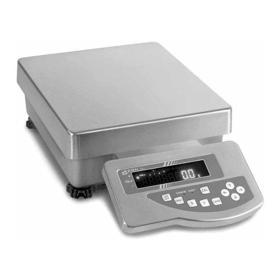
Summary of Contents for KERN FES 33K0.1 IPM
- Page 1 KERN & Sohn GmbH Ziegelei 1 Tel: +49-[0]7433- 9933-0 D-72336 Balingen Fax: +49-[0]7433-9933-149 E-Mail: info@kern-sohn.com Internet: www.kern-sohn.com Operating instruction Industrial scale KERN FES/FEJ Version 3.2 03/2011 FES/FEJ-BA-e-1132...
-
Page 2: Table Of Contents
KERN FES/FEJ Version 3.2 03/2011 Operating instruction Industrial scale Contents Technical data ....................5 Declaration of conformity ................7 Basic Information (General)................8 Proper use ........................8 Improper Use........................8 Warranty ........................8 Monitoring of Test Resources..................9 Basic Safety Precautions ................9 Pay attention to the instructions in the Operation Manual ..........9 Personnel training......................9... - Page 3 Configuration menu 2.................. 37 User principle of the menu control................37 Menu overview ......................38 Operation...................... 39 Keyboard overview .....................39 Overview of display ....................40 Weighing mode .................... 41 10.1 Weighing........................41 10.1.1 Taring ........................... 42 10.1.2 Net/gross..........................44 10.2 Weighing/parts counting .....................45 10.3 Weighing/percent determination.................48 10.3.1 Entering the reference weight by weighing................
- Page 4 Data output....................82 15.1 RS 232C interface ......................82 15.2 Printer interface (unidirectional data exchange) ............83 15.3 Description of interface....................83 15.4 Data output .........................84 15.4.1 Format for data transmission ....................84 15.4.2 Signs ............................ 85 15.4.3 Data............................85 15.4.4 Units ............................. 85 15.4.5 Result evaluation for balances with tolerance range ............
-
Page 5: Technical Data
Technical data KERN FES 17K0.1 IPM FES 33K0.1 IPM FES 62K0.1 DIPM Readability (d) 0.1g 0.1g 0.1g//1g Verification value (e) Weighing range (max) 17kg 33kg 6.2kg//62kg Accuracy class Warming up time (operating temperature) Taring range (subtractive) 17kg 33kg 62kg Minimum load (Min) Minimum piece weight 0.1 g... - Page 6 KERN FEJ 17K0.1 IPM FEJ 33K0.1 IPM FEJ 62K0.1 DIPM Readability (d) 0.1g 0.1g 0.1g//1g Verification value (e) Weighing range (max) 17kg 33kg 6.2kg//62kg Accuracy class Warming up time (operating temperature) Taring range (subtractive) 17kg 33kg 62kg Minimum load (Min) Minimum piece weight 0.1 g...
-
Page 7: Declaration Of Conformity
Electronic Balance: KERN PES, PEJ, FES, FEJ Mark applied EU Directive Standards 2004/108/EC EN 55022 (2006) 2006/95/EC EN 60950 (2001) Date: 07.10.2008 Signature: KERN & Sohn GmbH Management KERN & Sohn GmbH, Ziegelei 1, D-72336 Balingen, Tel. +49-[0]7433/9933-0,Fax +49-[0]7433/9933-149 FES/FEJ-BA-e-1132... -
Page 8: Basic Information (General)
The balance may only be used according to the described conditions. Other areas of use must be released by KERN in writing. The appliance may only be opened by trained service technicians according to KERN standards. -
Page 9: Monitoring Of Test Resources
Infor- mation is available on KERN’s home page (www.kern-sohn.com) with regard to the monitoring of balance test substances and the test weights required for this. In KERN’s accredited DKD calibration laboratory test weights and balances may be... -
Page 10: Unpacking, Setup And Commissioning
Unpacking, Setup and Commissioning 6.1 Installation Site, Location of Use The balances are designed in a way that reliable weighing results are achieved in common conditions of use. You will work accurately and fast, if you select the right location for your balance. Therefore, observe the following for the installation site: •... -
Page 11: Scope Of Delivery
6.3 Scope of delivery Serial accessories: 1. Balance 2. Cable box cover 3. Cover display holder 4. Display holder 5. Mains power supply 6. Operating Manual FES/FEJ-BA-e-1132... - Page 12 Accessories optional: 1. Stand (FEJ-A05) Remove closing cover in or- der to screw-on the hook. To protect against dust and hu- 2. Hook for underfloor midity put it again after the weighing (FEJ-A06) underfloor-weighing. 3. Relay output (FEJ-A07) FES/FEJ-BA-e-1132...
-
Page 13: Setup
6.4 Setup 1. Level balance with foot screws until the air bubble of the water balance is in the prescribed circle. Bubble level 2. Remove weighing plate Knobs Foot screws Cable box 3. Release the knobs on the display holder almost completely 4. - Page 14 7. Apply the cable box cover from above, bending the sides slightly outwards. 8. Hold the display a little inclined upwards and slide the lateral guiding noses under the lateral grooves of the display holder. Display Guiding noses 9. Re-install the weighing plate FES/FEJ-BA-e-1132...
-
Page 15: Assembly Instructions For The Use Of The Stand (Option)
10. Insert the display holder cover from the top above the two knobs of the display holder. It is locked in the groove on the display holder. Cover Cover Groove 6.4.1 Assembly instructions for the use of the stand (option) FES/FEJ-BA-e-1132... -
Page 16: Mains Connection
6.5 Mains connection Power is supplied via the external mains power supply. The stated voltage value must be the same as the local voltage. Only use original KERN mains power supplies. Using other makes requires consent by KERN. Cover plate... -
Page 17: Battery Power Supply
6.6 Battery power supply The optionally supplied battery is charged with the supplied power supply. Before the first use, the battery should be charged by connecting it to the mains power supply for at least 12 hours. The operating time of the battery is about. 6h. Charging time until complete recharging ca. -
Page 18: Initial Commissioning
6.8 Initial Commissioning In order to obtain exact results with the electronic balances, your balance must have reached the operating temperature (see warming up time chap. 1). During this warm- ing up time, the balance must be connected to the power supply (mains, accumulator or battery). -
Page 19: Bar Graph Display
6.8.2 Bar graph display half of weighing range weighing dish unloaded weighing range is used to full capacity The weighing range of the balance is divided into 40 graphic cuboids. Zero (0) will appear on the graphic display if there is no weighing value on the balance. 20 graphic cuboids are displayed if the balance is loaded up to one half of its weighing range. -
Page 20: Stability Display
6.8.3 Stability display Stable Unstable If the display shows the stability display [ο] the balance is in a stable status. The [ο] indication disappears if the condition is unstable. FES/FEJ-BA-e-1132... -
Page 21: Balance Zero Display
6.8.4 Balance zero display Environmental influences can lead to the exact figure of “000.0“ not being displayed in spite of an empty weighing dish. It is, however, possible to reset your balance to zero at any time and thus ensure that weighing really does commence at zero. Set- ting to zero when a weight is applied is only possible within a certain type-dependent range. - Page 22 Operation Display Activate function [w CA. 3] (see chap. 7). w CA 3 CAL EH T Zero point will be saved. If the display indicates [ PuSH. F ], press the -key Carefully place adjusting weight in the centre F.5. of the weighing plate If the display indicates [ PuSH.
-
Page 23: Adjustment Test With External Weight (Only Fes)
6.9.2 Adjustment test with external weight (only FES) During adjustment tests the balance automatically compares the saved value of the adjustment weight with the actual value. This is only a check, i.e. no values are changed. Procedure: Observe stable environmental conditions. A warming up time (see chap. 1) is re- quired for stabilization. - Page 24 D KFF Take away adjustment weight. Press any key; the adjustment process is cancelled and the balance returns to weighing mode. -z02 FES/FEJ-BA-e-1132...
-
Page 25: Adjustment With Internal Weight (Only Fej)
6.9.3 Adjustment with internal weight (only FEJ) With the internal adjustment weight, the weighing accuracy can be checked and re- adjusted at any time. Procedure when adjusting: Observe stable environmental conditions. A warming-up time (see chap. 1) for stabi- lisation is necessary. Ensure that there are no objects on the weighing plate. Position of the verifying switch to the right (verifying position). -
Page 26: Adjustment Test With Internal Weight (Only Fej)
6.9.4 Adjustment test with internal weight (only FEJ) During adjustment tests the balance automatically compares the saved value of the adjustment weight with the actual value. This is only a check, i.e. no values are changed. Procedure: Observe stable environmental conditions. A warming up time (see chap. 1) is re- quired for stabilization. - Page 27 D KFF The difference between the saved value -z02 and the measured value is displayed. Press any key; the adjustment process is cancelled and the balance returns to weighing mode. Error messages during adjustment function: 1. 3-Err: The weighing plate is not empty -> Remove goods to be weighed from weighing plate 2.
-
Page 28: Glp Log
The easiest way is to have a printer connected. Activate function (E.GLP – 1), see chap.7 Printout example: DATE 04.11.2008 Date TIME: 08:42 Time GOTTL.KERN&SOHN Company TYPE FEJ33K01IPM Model S/N Dxxxxxxxxx Serial no. Balance identification no. ID 1234 CAL.INTERVAL REF: Adjustment weight 033000.0 g... -
Page 29: Verification
6.11 Verification General introduction: According to EU directive 90/384/EEC balances must be verified if they are used as follows (legally controlled area): a) For commercial transactions if the price of goods is determined by weighing b) For the production of medicines in pharmacies as well as for analyses in the medical and pharmaceutical laboratory c) For official purposes. - Page 30 After verification the balance is sealed at the indicated positions. Verification of the balance is invalid without the "seal". Position of the “official seals“: Seals Seal Seal Balances with obligation to verify must be taken out of operation if: The weighing result of the balance is outside the error limit. Therefore, in regular intervals load balance with known test weight (ca.
-
Page 31: Application And Configuration Menu 1
Application and configuration menu 1 In the menu the settings of the balance can be modified and functions can be acti- vated. This way, the balance can be adjusted to individual weighing requirements. The menu is structured as follows Application menu: To adjust the balance to user requirements Configuration menu 1: Definition of the basic functions 7.1 User principle of the menu control... - Page 32 Changing the function: q SET 1 Further pressing the keys will call up the various functions of the menu (see table chapter 7.2) r SEL 0 Changing the parameter: r SEL 0 r SEL 3 To change the last digit of the parameter, actuate the TARE-key or the arrow keys.
-
Page 33: Menu Overview
7.2 Menu overview The manufacturer’s setting has a certain standard configuration. This one is marked with *. Function Display Selectio Description of the options * 1 Weighing 2 Combination: Weighing/parts counting Weighing mode q SET. 3 Combination: Weighing/percent determina- tion * 0 Off 1 Add Additional functions... - Page 34 0 Hide bar graph Bar graph x B.G. * 1 Show bar graph Automatic turn-off for bat- 0 Automatic turn-off for battery operation tery operation (function (optional) - off. y A.P. only exists for battery op- * 1 Automatic turn-off for battery operation eration) (optional) - on.
-
Page 35: Parameter For Serial Interface
7.2.1 Parameter for serial interface v K.F 0 Not shown for menu setting „ “ (interface de-activated). Function Display Selectio Description of the options No data output Continuous data output Continuous data output stable weighing val- Output for stable and instable weighing val- ues after pressing PRINT key Output for stable weighing value after previ- ous relief of balance... -
Page 36: Fes/Fej-Ba-E
Parity 0 No parity bit only at setting 1 Odd parity v K.F. 2 or 6s PA. v K.F. 3 2 Even parity Data Bits * 7 7 bits only at setting 6t D.L. v K.F. 3 8 8 bits Stop Bits 1 1 bit only at setting... -
Page 37: Configuration Menu 2
Configuration menu 2 8.1 User principle of the menu control Operation Display Switch on balance: Call up menu: Hold F-key while TARE key is pressed Fonm2 until [FWnm 2] is displayed. When releasing, the first function is dis- played [K. KD. -
Page 38: Menu Overview
Changing the parameter: q KD 0 q KD 1 To change the last digit of the parameter actuate TARE-key or arrow keys. Saving your settings: Leave the menu and return to weighing mode 8.2 Menu overview The manufacturer’s setting has a certain standard configuration. This one is marked with *. -
Page 39: Operation
Operation 9.1 Keyboard overview Choice Function • Turn on/off • Output of the weight value on an external device (printer) or PC • Save function parameters • Addition of displayed values in addition memory • Menu call up "Enter tolerance limits" •... -
Page 40: Overview Of Display
9.2 Overview of display Display Description g, kg Gram, Kilogram →0← Zeroing display Minus ο Stability display Net weight Gross /gross weight Parts counting Percent weighing Tolerance weighing Adding function active ∑ Total Output date/time Balance carries out balance function, e.g. unit count / display of stored value Display for adjustment. -
Page 41: Weighing Mode
10 Weighing mode The manufacturer’s standard configuration is "Weighing": Function [q SET.1], see chapter 7.2. Under this menu item, you can combine the function "Weighing" with the function “Parts counting” or “Percent determination” (settings see chapter 7.2). This way, 3 different weighing modes are available for you: 1. -
Page 42: Taring
10.1.1 Taring The dead weight of any weighing container may be tared away by pressing a button, so that the following weighings show the net weight of the goods to be weighed. Operation Display Place empty tare container on the weigh- ing plate. - Page 43 The taring process can be repeated any number of times, e.g. when adding several components for a mixture (adding). Reset display to "0": The total weight of the container is tared away. Add more components into the weighing container (adding). 457z9 Now read off the weight of the added item to be weighed on the display.
-
Page 44: Net/Gross
10.1.2 Net/gross The dead weight of any weighing container may be tared away by pressing a button. For subsequent weighings the net weight of the goods to be weighed as well as the gross weight goods + taring container can be displayed. Condition: •... -
Page 45: Weighing/Parts Counting
250z0 Use the F key to switch from net weight to gross weight or vice versa This procedure may be repeated any number of times (max. weighing range of 350z0 the balance). 10.2 Weighing/parts counting With parts counting you can either count parts into a container or remove parts from a container. - Page 46 Determine the reference unit: The display shows flashing the last saved reference quantity. Qn 10 Press for about 4 seconds, until [U. SEt.] is displayed, then The display e.g. 10 Pcs. prompts release you to enter 10 pieces as reference. Change reference quantity: Use the TARE-key or the arrow keys to Qn 30...
- Page 47 The reference weight is saved. Remove reference weight. Count the items: Now you can fill the items to be counted into the container. The respective quan- tity is shown in the display. By repeated pressing, switching option of the displayed value of the displayed value e.g.
-
Page 48: Weighing/Percent Determination
10.3 Weighing/percent determination Percent weighing allows to display weight in percent, in relation to a reference weight. The displayed weighing value is stored as a standard percent value (default setting: 100%). 10.3.1 Entering the reference weight by weighing Operation Display Activate function [q SET 3] (see chap. -
Page 49: Numeric Entering Of The Reference Weight
From now, the added weight is shown in %. 59t8 By repeated pressing, switching option of the displayed value in „g“ or %“ NOTE: • If the error message “o-Err “ is displayed, the reference weight is outside the weighing range •... - Page 50 With "0" flashing, you are prompted to enter the reference weight numerically Entering the numeric value: ⇒ ⇒ 1 ⇒ ≈ ⇒ ⇒ ⇒ Any time you press TARE-key or the ar- row key, you will go through the numbers 0-9, decimal dot and minus Select the number to be changed (the active position flashes):...
- Page 51 From now, the added weight is shown in %. 59t8 By repeated pressing, switching option of the displayed value in „g“ or %“ NOTE: • If the error message “o-Err “ is displayed, the reference weight is outside the weighing range •...
-
Page 52: Adding Of Displayed Values
Adding of displayed values Any number or individual weighings are automatically added to a total, e.g. all indi- vidual weighings of a batch. The add function is possible in all functions of the weighing mode (Weighing/parts counting/ percent determination). Operation Display 1. - Page 53 6. Wait until stability display is shown [ ] : 15z0 The displayed value is added into the ∑ total adding memory. 100z0 The total [ ∑ ] is briefly shown 15z0 Remove weight and place further weights on balance; for each weight, re- peat step 4 to 6 7.
-
Page 54: Weighing With Tolerance Range
Entering limits is possible for the following functions: • Weighing • Parts counting • Percent determination There are several functions available for tolerance control of the balance KERN FEJ. There are two different ways to carry out evaluation of limits: 1. Evaluation of absolute values [24. TXP.1]: An exact reference value (e.g. -
Page 55: Display Of The Results
There are two different ways to set the tolerance limits: 1. Place the values (object) on the balance - > Save this value 2. Numeric entering of values - > Enter the limits via keyboard. NOTE: If a limiting value was set it remains saved until the balance is turned off. For the functions weighing, counting, percent individual limits can be set. -
Page 56: For 3 Or 4 Limits
12.2.2 For 3 or 4 limits If 3 or 4 limiting points are to be set, this is displayed in the bar graph. The length of the represented bars indicates where within the tolerance range the weighed of the goods to be weighed are. A bar graph shows the different limits. - Page 57 Tab. 1: Function Display Selectio Description of options Tolerance marker is always displayed, even if standstill control is not yet dis- Display conditions of played. 21. CQ. the tolerance marker Tolerance marker is only displayed in connection with standstill control. Tolerance marker is only displayed above zero range (mind + 5).
-
Page 58: Evaluation Of Absolute Values
12.4 Evaluation of absolute values 12.4.1 Entering 2 limits by weighing Important information! Always begin by entering the lower limit value, followed by the upper limit value. Enter. Operation Display 1. Activate tolerance weighing function [2.SEL.2] or [2.SEL.3] (see chap. 7). r SEL 2 2. - Page 59 4. Entering limiting values: L. SET Press for about 4 seconds, until [L. SET] is displayed, then release The flashing display (last saved value) prompts you to enter the lower limiting value (L.SET) 5. Place sample for the lower (i.e. smaller) limiting value on the weigh- ing plate: 6.
- Page 60 7. Place sample for the upper (i.e. lar- ger) limiting value on the weighing plate: 8. Save: An acoustic signal sounds, the saved upper limit is briefly displayed. The balance returns to tolerance weigh- ing mode. From here evaluation takes place whether the goods to be weighed are within the two tolerance limits.
-
Page 61: Entering 3 Or 4 Limits By Weighing
12.4.2 Entering 3 or 4 limits by weighing Operation Display 1. Activate tolerance weighing function [2.SEL.2] or [2.SEL.3] (see chap. 7). r SEL 2 2. Actuate required parameter selection 2q CQ. 1 Parameter selection for 3 limiting points: until 2s P . 3 [23. - Page 62 4. Entering limiting values: L1. SET Press for about 4 seconds, until [L1 SET] is displayed, then release The flashing display (last saved value) prompts you to enter the first lower limit- ing value (LK.SET) 5. Place sample for the first limiting value on the weighing plate: An acoustic signal sounds, the saved 6.
- Page 63 8. Save: An acoustic signal sounds, the saved second weighing value is briefly dis- played. L3. SET The flashing display (last saved value) prompts you to enter the third limiting value (L3.SET) 9. To enter 3rd and 4th limiting value, repeat steps 7 and 8 10.
-
Page 64: Numeric Entering Of 2 Limits
12.4.3 Numeric entering of 2 limits Operation Display 1. Activate tolerance weighing function [2.SEL.2] or [2.SEL.3] (see chap. 7). r SEL 2 2. Actuate required parameter selection 2q CQ. 1 Parameter selection for 2 limiting points: until 2s P . 2 [23. - Page 65 Display changes to flashing "zero" The flashing display prompts you to nu- merically enter the lower limit 6. Entering numeric value for the lower limit ⇒ ⇒ 1 ⇒ ≈ ⇒ ⇒ ⇒ Any time you press the TARE-key or the arrow keys you will go through the num- bers 0-9, decimal dot and minus Select the number to be changed (the...
- Page 66 7. Save: An acoustic signal sounds, the saved lower weighing value is briefly displayed. H. SET The flashing display (last saved value) prompts you to enter the upper limiting value 8. To enter the numeric value for the upper limiting value, repeat steps 5 - 9.
-
Page 67: Evaluation With Difference Values
12.5 Evaluation with difference values 12.5.1 Entering 2 limits by weighing Important information! Always begin by entering the lower limit value, followed by the upper limit value. Enter. Operation Display 1. Tolerance weighing function [2.SEL.2] or [2.SEL.3] (see chapter r SEL 2 2. - Page 68 4. Entering a reference value: R. SET Press for about 4 seconds, until [R.SET] appears, then release. The flashing display (last saved value) prompts you to enter a reference value 5. Place reference weight onto weighing plate: 6. Save An acoustic signal sounds, the saved reference value is briefly displayed.* L.
- Page 69 7. Place sample for the first limiting value on the weighing plate: 8. Save An acoustic signal sounds, the saved lower difference value is briefly dis- played. H. SET The flashing display (last saved value) prompts you to enter the upper limiting value 9.
-
Page 70: Entering 3 Or 4 Limits By Weighing
12.5.2 Entering 3 or 4 limits by weighing To enter 3 or 4 limiting values [L1 SET] - [L3 SET] or [L4 SET], repeat steps 7 and 8 (see also chapter 12.4.2). 12.5.3 Numeric entering of 2 limits Operation Display 1. - Page 71 4. Entering a reference value: R. SET Press for about 4 seconds, until [R.SET] appears, then release. The last saved reference weight appears flashing Display changes to flashing "zero" The flashing display prompts you to numerically enter a reference weight 6.
- Page 72 7. Confirm An acoustic signal sounds, the saved reference weight is briefly displayed. L. SET The flashing display (last saved value) prompts you to enter the lower differ- ence value 8. Entering lower limit Repeat steps 5 and 6 9. Confirm An acoustic signal sounds, the saved lower difference value is briefly dis- played.
-
Page 73: Setting Date And Time
11. Save An acoustic signal sounds, the saved upper difference value is briefly dis- played. The balance returns to tolerance weigh- ing mode. From here evaluation takes place whether the goods to be weighed are within the two tolerance limits. To enter 3 or 4 limiting values [L1 SET] - [L3 SET] or [L4 SET], repeat steps 8 and 9 (see also chapter 12.4.2). - Page 74 TKNE Press again 15 OO OO Last stored time appears.* 2. Resetting time 15 OO OO Time to be changed is flashing Select the number to be changed (the active position flashes): 15 OO OO Changing the numerical value 15 O : 7 3 : After storing your setting, the date 3.
-
Page 75: Date
13.2 Date F. DATE You can set the display of your data output under menu item [ (see menu overview chap. 7.2.). Operation Display 1. Call up menu Fonm Keep pressed until [D-SET] appears. D-SET TKNE Press again 15 OO OO Last stored time appears DATE Press again... - Page 76 2. Resetting the date 7-1 - 5 Time to be changed is flashing Select the number to be changed (the active position flashes): 7-1 - 5 Changing the numerical value 8-1 - 5 After storing your settings, the balance 3. Save will automatically return to weighing mode.
-
Page 77: Description Of Individual Functions
Description of individual functions 14.1 Auto sleep function In this function the display of the balance is turned off after 3 minutes without load change or operation to save energy. Parameter selection: [ The Auto sleep function is indicated by a red LED. NOTE: This function is only available when connected to the mains power. -
Page 78: Interval Output Function
14.5 Interval output function This menu item allows you to determine after which interval you wish data output to 61. Q.m A 61. Q.m B be carried out. To achieve this, activate the [ ] or [ ] function in the menu (see chpt. 7.2.1) 14.5.1 Interval setting Operation Display... -
Page 79: Start/Stop Interval Output
14.5.2 Start/Stop interval output Operation Display START Start output Stop output The balance returns automatically into weighing mode. FES/FEJ-BA-e-1132... -
Page 80: Input Balance Id-No
14.6 Input balance ID-no. Display symbol [ ] and [ You can enter a 6-digit number using the characters [0-9], [A-F] and [ - ]. Space character is displayed as [ _ ]. Operation Display 1. Call up menu Fonm2 When releasing, the first function is dis- played [K. - Page 81 Select the number to be changed (the active position flashes): 000001 Changing the numerical value 000501 Your setting will be stored and the next 5. Save: menu item will appear. 2.CRCA. O 6. Return to weighing mode FES/FEJ-BA-e-1132...
-
Page 82: Data Output
15 Data output The regular equipment of the balance includes an RS 232C interface and a printer interface. 15.1 RS 232C interface The RS 232C interface allows a bi-directional data exchange from the FEJ to external devices. This data exchange is asynchronous using ASCII - Code. Pin allocation of balance output plug: Pin nr. -
Page 83: Printer Interface (Unidirectional Data Exchange)
15.2 Printer interface (unidirectional data exchange) Pin allocation of balance output plug: Pin nr. Signal Input/Output Function EXT.TARE Input External tare function Output Transmit data Signal ground 15.3 Description of interface The selection of a certain operating mode allows you to set the output format, the output control, the transmission speed and the parity bit. -
Page 84: Data Output
15.4 Data output 15.4.1 Format for data transmission Any of the data formats below may be set by selecting the relevant function on the balance ( see menu overview chap. 7.2): • 6-digit data format Consisting of 14 words, including final character; CR=0DH, LF=0AH (CR=balance reverse motion / LF=line feed) •... -
Page 85: Signs
15.4.2 Signs P 1 = 1 word Code Meaning 2 B H Data is 0 or positive 2 D H Data is negative 15.4.3 Data 6-digit data format (D1-D7): 7 words 7-digit data format (D1-D8): 8 words 6-digit data format e = 10 d (D1-D7): 7 words 7-digit data format e = 10 d (D1-D8): 8 words... -
Page 86: Result Evaluation For Balances With Tolerance Range
15.4.5 Result evaluation for balances with tolerance range S 1 = 1 word Code Meaning Goods to be weighed below tolerance limit 1- or 2 end Goods to be weighed within tolerance range points Goods to be weighed above tolerance limit Limit 1 Limit 2 3- or 4 end... -
Page 87: Output Time
15.4.8 Output time * hh: Hours (00-23), mm: Minutes (00-59) min: Seconds (00-59) s: 15.5 Remote control instructions Code Meaning No data output Continuous data output Continuous data output stable weighing values Output for stable and instable weighing values after pressing PRINT key Output for stable weighing value after previous re- lief of balance... -
Page 88: Service, Maintenance, Disposal
When cleaning please ensure that the membrane is not damaged or soiled. 16.2 Service, maintenance The appliance may only be opened by trained service technicians who are authorized by KERN. Before opening, disconnect from power supply. 16.3 Disposal Disposal of packaging and appliance must be carried out by operator according to valid national or regional law of the location where the appliance is used. -
Page 89: Instant Help
17 Instant help In case of an error in the program process, briefly turn off the balance and disconnect from power supply. The weighing process must then be restarted from the beginning. Help: Fault Possible cause • The balance is not switched on. The displayed weight does not glow.
Need help?
Do you have a question about the FES 33K0.1 IPM and is the answer not in the manual?
Questions and answers