
Related Manuals for Sungrow SG3KTL-EC


Summary of Contents for Sungrow SG3KTL-EC
- Page 1 User Manual SG3KTL-EC / SG4KTL-EC/ SG5KTL-EC / SG6KTL-EC PV Grid-Connected Inverter SG3_4_5_6KTL-EC-UEN-Ver15-201508 Version:1.5...
-
Page 3: About This Manual
About This Manual This manual is for the inverters SG3KTL-EC, SG4KTL-EC, SG5KTL-EC, and SG6KTL-EC (hereinafter referred to as inverter unless specified otherwise). They are grid-connected, transformer-less, robust inverters with high conversion efficiency. The devices will bring you profit for PV power system. - Page 4 Symbols Explanation Important instructions contained in this manual should be followed during installation, operation and maintenance of the inverter. And they will be highlighted by the following symbols. DANGER indicates a hazard with a high level of risk which, if not avoided, will result in death or serious injury.
- Page 5 Symbols on the Inverter Body Disconnect the inverter from mains and PV generator before service! Do not touch any inner live parts until 10 minutes after disconnection from the utility grid and the PV input. Hot surface! In order to reduce the risk of burns, do not touch the hot surface when the device is running.
-
Page 6: Table Of Contents
Contents About This Manual ................I 1 Safety Instructions ..............1 2 Product Introduction ............... 6 Intended Usage ...................... 6 Product Description ....................7 2.2.1 Inverter Appearance ....................7 2.2.2 Inverter Dimensions ....................8 ... - Page 7 5.4.2 Assembling AC Cables to Connector .............. 29 Connecting Inverter to PV Arrays ..............30 5.5.1 PV Inputs Configuration ..................31 5.5.2 Assembling DC Cable to Connector ..............33 5.5.3 DC Wiring Procedure ..................... 35 ...
- Page 8 Inspection before Commissioning ............... 58 Commissioning Procedure ................58 8 Disconnecting, Dismantling and Disposing of the Inverter 61 Disconnecting the Inverter ................61 Dismantling the Inverter .................. 62 Disposing of the Inverter ................. 62 9 ...
- Page 9 11.1.1 For Common User ....................83 11.1.2 For Professional User ..................84 11.2 Registration and Adding PV Plant ..............87 11.3 Viewing Information via the APP ..............91 11.3.1 Acquisition and Installation of the APP ............91 ...
-
Page 11: 1 Safety Instructions
1 Safety Instructions IMPORTANT SAFETY INSTRUCTIONS The inverters have been designed and tested strictly according to the international safety regulations. As electrical and electronic equipments, safety instructions related to them must be complied with during installation, commissioning, operation and maintenance. Incorrect operation or work may result in damage to ... - Page 12 1 Safety Instructions User Manual Before Installation There is a risk of injury due to improperly handling the device! Always follow the instructions contained in the manual when moving and positioning the inverter. The weight of the equipment can cause injuries, serious wounds, or bruise if improperly handled.
- Page 13 User Manual 1 Safety Instructions Lethal voltage! PV arrays will produce electrical energy when exposed to sunlight and thus can create an electrical shock hazard. Wiring of the PV arrays should be performed only by qualified personnel. All cables must be firmly attached, undamaged, properly insulated and adequately dimensioned.
- Page 14 1 Safety Instructions User Manual Maintenance and Service Always keep in mind that the inverter is power supplied by dual power sources: PV arrays and utility grid. There is a risk of inverter damage or personal injury due to incorrect service work! Before any service work, you should obey the following procedures.
- Page 15 User Manual 1 Safety Instructions There is a risk of inverter damage due to electrostatic discharge! The printed circuit boards contain components sensitive to electrostatic discharge. Wear a grounding wrist band when handling the boards. Avoid unnecessary touch with the boards during replacement. Others The selected country settings can be changed only by service personnel! Unauthorized alternation of the country settings is prohibited.
-
Page 16: 2 Product Introduction
Fig. 2-1 Inverter Application in the PV Power System Item Description Remark PV strings Monocrystalline silicon, polycrystalline silicon, and thin-film of protection class II without grounding. Inverter SG3KTL-EC, SG4KTL-EC, SG5KTL-EC and SG6KTL-EC. Metering device Meter cupboard with power distribution system. -
Page 17: Product Description
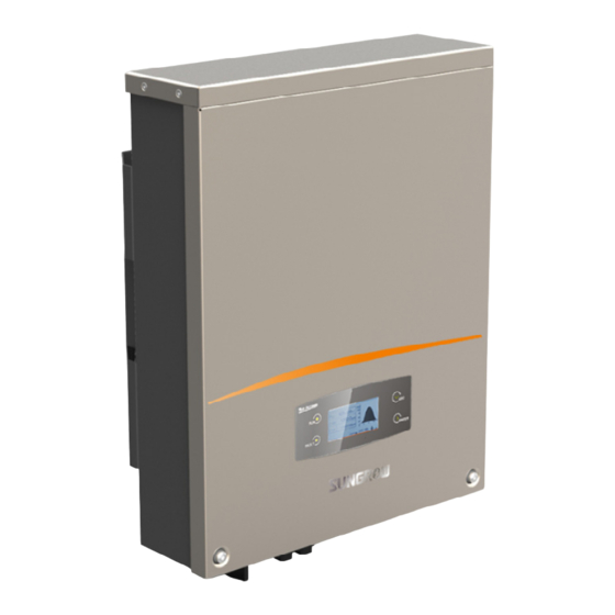
User Manual 2 Product Introduction Item Description Remark Smart energy Three-phase electronic energy meter, used to measure meter (optional) the active power output. Communicate with the inverter via RS485 port. Utility grid TT, TN-C, TN-S, TN-C-S. Household load Household appliances. 2.2 Product Description 2.2.1 Inverter Appearance Fig. -
Page 18: Inverter Dimensions
Fig. 2-3 Outline Dimensions Tab. 2-1 Dimension Values Type W(mm) H(mm) D(mm) Net weight(kg) SG3KTL-EC SG4KTL-EC SG5KTL-EC SG6KTL-EC 2.2.3 LCD Display Panel As a human-computer interaction interface, LCD display panel is on the front panel and comprises LED indicators, buttons and LCD screen. -
Page 19: Technical Description
User Manual 2 Product Introduction Name Description LED indicators “RUN” and “FAULT”. The current running state can be known from the two indicators. Detailed definition is shown in Tab. 2-2. Buttons User can operate the LCD menu via the two buttons. Detailed function is shown in Tab. -
Page 20: Functions Description
Zero export (0% feed-in function, optional) At the grid-connection point, the three-phase SUNGROW Energy Meter is used for measuring the feed-in power. Enable the feed setting and set the limit value via the LCD menu. Then the inverter will run with power derating once the meter detects that the feed-in power is above the set value. - Page 21 User Manual 2 Product Introduction − Residual current monitoring − DC injection of AC output current surveillance − Anti-islanding protection − DC over-voltage protection − DC over-current protection − Power module over-temperature protection...
-
Page 22: 3 Unpacking And Storing
3 Unpacking and Storing 3.1 Unpacking and Inspecting The device is thoroughly tested and inspected before delivery. Although sturdy packaging is used, damage may still occur during shipping. If there is visible damage to the packaging or the inner contents, or anything missing, contact the device dealer. -
Page 23: Identifying The Inverter
They provide information about the inverter type, the most important specifications, marks of certification institutions, website and serial number which are available and identified by SUNGROW. Fig. 3-2 Nameplate of Inverter *Image shown here is for reference only. Actual product you receive may differ. -
Page 24: Delivery Contents
3 Unpacking and Stor User Manual 3.4 Delivery Contents Fig. 3-3 Delivery Contents *Image shown here is for reference only. Actual product you receive may differ. Item Description Inverter. Wall bracket used to mount inverter onto the wall. Expansion bolts for fastening wall bracket onto concrete wall. Fastener set for installing wall bracket onto metal frame. -
Page 25: Storing The Inverter
If there is more than one inverter to be stored, the maximum layers for original paper packaging are three. After long-term storage, local installer or Service Dept. of SUNGROW should perform a comprehensive test before connecting the inverter into PV power system. -
Page 26: 4 Securing Inverter To The Wall
4 Securing Inverter to the Wall 4.1 Selecting Installation Location Selecting an optimal installation location for the inverter is decisive for its operating safety as well as its expected efficiency and service life. 1. Take the load capacity of the wall into account. The wall (such as concrete wall and metal structure) should be strong enough to hold the weight of the inverter over a long period. - Page 27 User Manual 4 Securing Inverter to the Wall 5. Install the device at eye level for easy buttons operation and display reading. 6. It is suggested that the inverter be installed vertically with upside up for good heat dissipation. 7. Never install the inverter horizontally, or with a forward tilt or with a backward tilt or even with upside down.
- Page 28 4 Securing Inverter to the Wall User Manual 9. The ambient temperature should range from -25°C to 60°C. The power output will reduce when ambient temperature exceeds 45°C. 10. The maximum relative humidity of chosen installation site should never exceed 100%. 11.
-
Page 29: Moving Inverter To Installation Site
User Manual 4 Securing Inverter to the Wall 13. For multiple inverters installation, position the inverters side by side. For multi-row inverters installation, position the inverters in a staggered arrangement. 14. Do not install the inverter in a enclosed cabinet. Otherwise, the inverter will not operate normally. -
Page 30: Installing The Inverter
4 Securing Inverter to the Wall User Manual 4.3 Installing the Inverter Inverter is installed onto the wall by means of wall bracket in the packaging. Fig. 4-1 Dimensions of wall bracket(unit: mm) There are two sets of stainless fasteners supplied to attach the wall bracket to the concrete wall and metal frame respectively. - Page 31 User Manual 4 Securing Inverter to the Wall In order to avoid electrical shock or other injury, inspect if there is electricity or plumbing installations before drilling holes. Attach the wall bracket to the wall with the supplied expansion bolt set. The torque for fastening the nut should be at least 35 Nm.
- Page 32 4 Securing Inverter to the Wall User Manual To protect the inverter from theft, you can lock it to the wall bracket with a padlock. On Metal Frame If the chosen mounting location is metal frame, please proceed as follows to mount the inverter.
- Page 33 User Manual 4 Securing Inverter to the Wall Lift up the inverter above the wall bracket with the help of other people and then slide down. Make sure that the grooves on the back of the inverter and the hooks on the wall bracket engage perfectly. The installers must wear gloves to avoid scratches when mounting the inverter.
-
Page 34: 5 Electrical Connection
5 Electrical Connection Once the inverter is firmly attached to the appropriate location, it can be connected into the PV power system. Improper operation during the wiring process can cause fatal injury to the operators or unrecoverable damages to the inverter. Only qualified personnel can perform the wiring work. - Page 35 PV arrays The maximum open-circuit voltage of each PV string is 1000 V. SolarInfo logger It can be ordered from SUNGROW. Or use compatible logger from Meteo-Control, Solar-Log or Papendorf SE Remote PC User uses this device to monitor the whole PV system.
-
Page 36: Terminals Description
5 Electrical Connection User Manual 5.2 Terminals Description All electrical terminals are located at the bottom of the inverter. Fig. 5-2 shows the connection area. Enough space around the inverter should be kept for electrical connection when choosing the installation site. Fig. -
Page 37: Connecting Inverter To Grid
Inverter Type Specification for AC Circuit Breaker SG3KTL-EC SG4KTL-EC SG5KTL-EC SG6KTL-EC It is not allowed for several inverters to use the same circuit breaker. - Page 38 Requirements of Multiple Inverters in Parallel Grid Connection If several inverters are operated in parallel connection to grid, different requirements should be obeyed (See technical information “Technical notes for multiple-paralleled grid-connected inverters” in the download area of SUNGROW website). AC Cable Requirements The grid is connected to the inverter via 5 wires (L1, L2, L3, N and PE).
-
Page 39: Assembling Ac Cables To Connector
User Manual 5 Electrical Connection Type Single Conductor Cross Total Outer cable Maximu Section diameters m Cable Range Recommended Range Recommended Length 4…10 4…10 mm² SG3/4/5/6K mm²(AW 11…20 (AWG11…AWG 15 mm 100 m TL-EC G11…A WG7) Withstand ambient temperature; ... -
Page 40: Connecting Inverter To Pv Arrays
5 Electrical Connection User Manual AC Wiring Procedure Unscrew the water-proof terminal in the following direction. Insert appropriate size AC cables into the water-proof terminal. Strip off insulation layer of all AC cables. The length of strip insulation is approximately 10 mm. Fix all cables ends to the corresponding terminals with the torque of 1 Nm according... -
Page 41: Pv Inputs Configuration
User Manual 5 Electrical Connection Make sure that the maximum input-ground capacity of the inverter is less than (0.12 uf/kW) * 3 kW/4 kW/5 kW/6 kW, otherwise the inverter will not function properly. Before connecting the PV arrays to the inverter, make sure that the impedances between the positive terminal of the PV string and Earth and the impedances between the negative terminal of the PV string and Earth are larger than 200 Kohm. - Page 42 Power Open-circuit Short-circuit Type Area Limit Voltage Limit Current Limit Each Input for Each Input for Each Input SG3KTL-EC 3191 W 1000 V 12.4 A SG4KTL-EC 4255 W 1000 V 12.4 A SG5KTL-EC 5265 W 1000 V 12.4 A SG6KTL-EC...
-
Page 43: Assembling Dc Cable To Connector
Open-circuit Short-circuit Total DC Power Type Voltage Limit for Current Limit for Limit for Inverter Each Input Total Input SG3KTL-EC 3191 W 1000 V 24.8 A SG4KTL-EC 4255 W 1000 V 24.8 A SG5KTL-EC 5265 W 1000 V 24.8 A... - Page 44 5 Electrical Connection User Manual Type Cross-Section Outer Cable Max. Max. Area Range Diameters Withstand Withstand Voltage Current Same with 4...6 mm SG5KTL-EC 6…9 mm 1000 V short-circuit 12AWG-10AWG current. Same with 4...6 mm SG6KTL-EC 6…9 mm 1000 V short-circuit 12AWG-10AWG current.
-
Page 45: Dc Wiring Procedure
User Manual 5 Electrical Connection For further assembly and connection instruction, please visit the webpage of the device manufacturer. 5.5.3 DC Wiring Procedure Make sure that none of the DC or AC cables connected to the inverter is live before the electrical work. Make sure that the open circuit voltage does not exceed inverter input limit of 1000 V, even under the lowest operating temperature. - Page 46 5 Electrical Connection User Manual Check the cable connection of PV strings for the correct polarity and that the open-circuit voltage does not exceed the inverter input limit 1000 V, even under the lowest operating temperature. Refer to module specification supplied by module manufacturer for detailed information.
-
Page 47: Grounding The Inverter
User Manual 5 Electrical Connection PV Connection of Parallel Mode Connect the inverter to PV arrays according to the following procedures: Rotate the DC switch at the bottom to the “OFF” position. Check the cable connection of PV strings for the correct polarity and that the open-circuit voltage does not exceed the inverter input limit 1000 V. -
Page 48: Second Protective Earth Terminal
5 Electrical Connection User Manual Where there is only one inverter in the PV power system, connect the “PE” cable to the installation ground. Where there are multiple inverters in the PV power system, connect the “PE” cables of all inverters and mounting frame of PV arrays to the same copper bus bar. In this way, they are in equipotential connection. -
Page 49: Communication Connection
User Manual 5 Electrical Connection Fig. 5-4 Second PE Terminal Second PE Connection Item Description Specification Screw M4×12 mm Spring washer Washer Cable socket 6 mm -10 mm copper wire or Yellow-green cable 10 mm -16 mm aluminum wire Fig. 5-5 Connection of the Second PE Connection 5.7 Communication Connection 5.7.1 Interfaces Overview All communication terminals are located on the bottom of the inverter. -
Page 50: Rs485 Communication Connection
5 Electrical Connection User Manual For RS485 serial communication, the inverter operation information can be transferred via RS485 port to a PC with monitoring software, or to data logging device (such as MC Logger). The inverter operation information can also be transferred via Wi-Fi terminal to a PC with monitoring software, or to SolarInfo Bank via the router. - Page 51 If the communication system is equipped with SolarInfo Logger, inverters may be remotely monitored via SolarInfo Bank. SolarInfo logger and RS485-232 converter are optional parts and can be ordered from SUNGROW. Wi-Fi Connection Procedure Unscrew the waterproof lid from the Wi-Fi terminal.
-
Page 52: Ethernet Communication Connection
5 Electrical Connection User Manual the RS485 A and B cables (3 and 6) to terminating resistor or data logging device or RS 485-232 converter. Connect the other devices. Refer to the device manual for the definition of the communication port. The following figure shows the RS485 connection to the three-phase smart energy meter. - Page 53 User Manual 5 Electrical Connection Fig. 5-7 Single inverter Ethernet connection The Ethernet communication of the daisy chain is done via external router or switch. Fig. 5-8 Inverters Ethernet connection in star topology The maximum number of inverters connected depends on switch, router and other factors.
- Page 54 5 Electrical Connection User Manual Ethernet Connection Procedure Remove the waterproof lid from the NET port. Use the Ethernet crimper to crimp the cable and connect the cable to RJ45 plug according to TIA/EIA 568B. Insert the RJ45 plug into the front plug connector until it makes a clicking sound.
-
Page 55: Power Control Configuration
User Manual 5 Electrical Connection 5.7.4 Power Control Configuration There is a terminal (DI) located on the bottom of the inverter for power control configuration. Prior to DI connection, please prepare additional required materials: Item Type Description DI: 5 cores cable DI connection cable Total diameter: 4…8 mm Stripping plier... - Page 56 5 Electrical Connection User Manual Fig. 5-9 Connecting the ripple control receiver for inverters with Ethernet connections In the Ethernet communication connection, only one inverter can be set as master inverter, others shall be set as slave inverters. Item Description Master inverter Slave inverter Ethernet cable...
- Page 57 User Manual 5 Electrical Connection Lead the DI connection cables through the Thread-Lock Sealing Nut and the cable gland. Strip off the DI cables as shown below. Description Remark Accepted cable external diameter ranges from Protective layer 4 mm to 8 mm. Length of insulation to be 7 mm stripped off...
- Page 58 5 Electrical Connection User Manual Insert the six-pole plug into the DI connection socket according to markings shown below. Fasten the Thread-Lock Sealing Nut to the inverter. Before fasten the lid, please make sure: Whether it’s necessary to apply glue on the cut; ...
-
Page 59: 6 Visiting And Configuring The Webserver
6 Visiting and Configuring the Webserver 6.1 User and Authority The Webserver provides user permission and installer permission. To avoid two or more persons to change the inverter configurations at the same time, only one person can login to Webserver at a time. Therefore, once a person logs in and does not exit, other person cannot log in anywhere else. -
Page 60: Main Interface
6 Visiting and Configuring the Webserver User Manual 6.3 Main Interface Fig. 6-1 Webserver-user interface Name Description Status bar Language selection and user login information. Device info The serial number of the running inverter. Operation information, parameter setting, history record, grid dispatching, system information, in which, Navigation bar parameter setting and history record have their second level menus. -
Page 61: Detailed Information
User Manual 6 Visiting and Configuring the Webserver Tab. 6-1 Explanation of the icons Icon Name Description : Inverter is not in the fault state; Current status : The inverter is in fault state. (DSP and LCD communication fault, and the fault of the inverter.) reduction reduction due to the use of inverter Total runtime... -
Page 62: Parameter Settings
6 Visiting and Configuring the Webserver User Manual 6.4 Parameter Settings Parameter settings include system parameters, operating parameters, protection parameters, and communication parameters. 6.4.1 System Parameters This interface is to set time and energy adjustment. 6.4.2 Operating Parameters This interface is for Austria and Vorarlberg to set the standby time, recovery time, insulation resistance, active power settings, and reactive power regulation. -
Page 63: Protection Parameters
This interface is for Germany and others to set the standby time, recovery time, insulation resistance, active power settings, and reactive power regulation. To set the Q(P) or Q(U) parameters, please contact SUNGROW to get the installer authority first. 6.4.3 Protection Parameters This interface is for Australia to select the country, company, single protect stage or multiple protect stage. - Page 64 This interface is for Germany and others to select the grid codes, such as voltage, country, single protect stage or multiple protect stage. To set protection parameters mentioned above, please contact SUNGROW to get the installer authority first.
-
Page 65: Communication Parameters
User Manual 6 Visiting and Configuring the Webserver 6.4.4 Communication Parameters This interface is to set the related communication parameters. The newly set parameters will not be effective immediately. System will adopt the new communication parameter after exiting. Both users and installers can set abovementioned communication parameters. -
Page 66: Fault Record
6 Visiting and Configuring the Webserver User Manual 6.5.2 Fault Record This interface is to view the inverter detailed fault records. At most 100 fault records can be stored with 10 records in each page. 6.5.3 Event Record This interface is to view the inverter event records. At most 100 event records can be stored with 10 records in each page. -
Page 67: System Information
It is recommended to perform grid dispatching as per default setting of each configuration status. The change of related parameters must be done only by qualified personnel. Any breach may void warranty claims from SUNGROW. 6.7 System Information This interface is to change the login password, perform load default and check... -
Page 68: 7 Commissioning
Commissioning Commissioning is a critical part for a well-installed PV system, which can protect against fires, injury and electrical shock. 7.1 Inspection before Commissioning Before starting the inverter, you should check the items as follows. The inverter is accessible for operation, maintenance and service. Re-check and confirm that the inverter is firmly installed. - Page 69 User Manual 7 Commissioning Country selection screen will prompt. Perform country settings with the right two buttons. Detailed button functions can be found in “10.1 Description of Button Function”. Press to choose country code. Confirm the settings by Pressing ENTER. Refer to “10.9.2 Selecting the Country Code”...
- Page 70 7 Commissioning User Manual Configure time according to the local time. Time setting is very important, which directly affects data logging. Press to move cursor and Press to scroll up time value. Confirm the settings by Pressing ENTER. The date format is YY/MM/DD.
-
Page 71: 8 Disconnecting, Dismantling And Disposing Of The Inverter
8 Disconnecting, Dismantling and Disposing of the Inverter 8.1 Disconnecting the Inverter For maintenance or other service work, the inverter must be switched off. In normal operation, switching off is not necessary. In order to disconnect the inverter from the AC and DC power sources, proceed as follows. -
Page 72: Dismantling The Inverter
8 Disconnecting, Dismantling and Disposing of the Inverter user manual For further disconnection and conductor reconnection instruction, please visit the webpage of device manufacturer. 8.2 Dismantling the Inverter Refer to Chapter 4 and Chapter 6 for the inverter dismantling in reverse steps. If necessary, remove the wall bracket from the wall. -
Page 73: 9 Troubleshooting And Maintenance
2. Perform troubleshooting in according to the fault type in LCD screen. See “9.1.2 Troubleshooting of Faults on LCD Screen”. 3. If it cannot be solved, please contact SUNGROW. 9.1.2 Troubleshooting of Faults on LCD Screen When faults occur, “Fault” state will be shown on the main screen. Press to view multiple “current fault”... - Page 74 The DC component of AC 1. Wait a moment for inverter recovery. current exceeded 2. Contact SUNGROW if the fault reoccurs. inverter limit. Inverter has detected that 1. Check the PV strings for ground fault. there is a leakage current.
- Page 75 Troubleshooting fault 2. Check AC cables for appropriate size. 3. Wait a moment for inverter recovery. 4. Contact SUNGROW if the fault reoccurs. The inverter has detected that there is unbalance 1. Wait a moment for inverter recovery. among the three phase 2.
- Page 76 1. Wait a moment for inverter recovery. AC current has exceeded 2. Contact SUNGROW if the fault reoccurs. the hardware limit. 1. Check the voltage of the grid. Grid over-frequency. 2. If the grid voltage exceeds the...
- Page 77 Specification Troubleshooting fault 3. Wait until the inverter reverts to normal; 4. Contact SUNGROW if the fault reoccurs. Open circuit voltage of 1. Check whether the configuration of PV the PV array is too high, array exceeds the permissible range of the leading the input power inverter.
-
Page 78: Maintenance
9 Troubleshooting and Maintenance User Manual Should you have any problems in operating the inverter, please contact Service hotline: +86 551 6532 7834/6532 7845 Email: service@sungrow.cn We need the following information to provide you the best assistance: Type of the inverter ... -
Page 79: Maintenance Instruction
Clean the air inlet and outlet with soft brush or vacuum cleaner if necessary. Battery Maintenance There is a button battery on the inner LCD PCB board. Contact SUNGROW Service Dept. to replace the battery when it is end of service life. -
Page 80: 10 Operating The Lcd Menu
10 Operating the LCD Menu 10.1 Description of Button Function Inverter offers two buttons for the user to look up the running information and configure parameters. The two buttons have multiple functions. Please refer to Tab. 10-1 before any operation onto inverter. Tab. -
Page 81: Inverter Menu Structure
User Manual 10 Operating the LCD Menu 10.2 Inverter Menu Structure Fig. 10-1 Menu Tree-English... -
Page 82: Main Screen
10 Operating the LCD Menu User Manual 10.3 Main Screen If the inverter succeeds in commissioning, LCD display will enter into the main screen, as shown in Fig. 10-2. Fig. 10-2 Main Screen Description Description Icons (refer to the Tab. 10-3) and the active power limits (P-W limits). Current output power. - Page 83 PV connection is correct. If no anomaly is found, disconnect DC switch and grid switch to restart. If it still does not work, contact SUNGROW. If inverter is in “Fault” state, Press to view multiple “Current fault”...
-
Page 84: Adjusting Contrast
10 Operating the LCD Menu User Manual The last three icons don’t exist when access the APP of SolarInfo Bank in local mode. 10.4 Adjusting Contrast 1. Press to enter into the contrast adjustment screen. 2. Press to increase the setting value and press to decrease the value. - Page 85 User Manual 10 Operating the LCD Menu Vdc: DC voltage of PV2 input. Idc: DC current of PV2 input. Pdc: DC power of PV2 input. Vac: Voltage of L1. Iac: Current of L1. Pac: AC output of L1. F: Frequency of L1. Vac: Voltage of L2.
-
Page 86: Starting And Stopping The Inverter
10 Operating the LCD Menu User Manual SN: Serial number. MAC: Physical address. The power value indicated by each column of the histogram represents the average value of the power during the related unit interval. 10.6 Starting and Stopping the Inverter Main Screen (Press ENTER)... -
Page 87: Button Operation For Parameters Setting
User Manual 10 Operating the LCD Menu A password confirmation screen will occur. Press to move cursor right and Press input the password 111111. Press ENTER to confirm the password and enter the “Set-param” submenu. 10.8 Button Operation for Parameters Setting The button functions for parameter setting in submenus may differ from that in other menus. -
Page 88: Selecting The Country Code
10 Operating the LCD Menu User Manual Main Screen (Press ENTER)→Menu screen (Press ×2)→Set-param (Press ENTER)→Enter password (Press ENTER)→Time (Press ENTER) On the “Time” screen, Press to move the cursor right and Press to set the correct date and time. Confirm settings by pressing ENTER. - Page 89 User Manual 10 Operating the LCD Menu (Optional) When the country code “AU” and the grid standard “Manual” are selected, Press ENTER to enter the “Pro-Stage” interface. Press choose the correct stage. Press to move cursor and Press to scroll up time value.
-
Page 90: Feed Setting
10 Operating the LCD Menu User Manual 10.9.3 Feed Setting ×2)→Set-param (Press Main Screen (Press ENTER)→Menu screen (Press ENTER)→Enter password (Press ENTER)→Set-param (Press ENTER, Press ×2)→ Feed Setting (Press ENTER) / Press to enable or disable the feed setting and Press ENTER to confirm. -
Page 91: Load Default
User Manual 10 Operating the LCD Menu Scroll pages by pressing ENTER. Apply an IP address, subnet mask, default gateway and port number for the inverter from your network administrator. If there is more than one inverter and all the inverters are set to DHCP [OFF], a unique IP address should be assigned to each inverter. - Page 92 10 Operating the LCD Menu User Manual Main Screen (Press ENTER)→Menu screen (Press ×2)→Set-param (Press ENTER)→Enter password (Press ENTER)→Set-param (Press ENTER, Press ×5)→Load Default (Press ENTER) Press ENTER to confirm “load default”.
-
Page 93: 11 Viewing Pv Plant Information
11 Viewing PV Plant Information After registering on the webpage www.solarinfobank.com, users can view PV plant information through the PC or smartphone. Users can also view PV plant information through the APP of SolarInfo Home installed into the smartphone. 11.1 SolarInfo Bank Connection 11.1.1 For Common User Connect the communication cable between router and inverter, and connect... -
Page 94: For Professional User
Scenario 3 The inverter is connected directly to Contact service engineer of the net port. SUNGROW when the inverter and the PC are in different subnets. Connect the communication cable. Set the DHCP to OFF and set the IP address, subnet mask, gateway, DNS1 and DNS2, as shown in the following figure. - Page 95 User Manual 11 Viewing PV Plant Information Wait for about 10 minutes and the icon as shown in the figure below will appear on the main LCD display interface. The SolarInfo Bank connects to the inverter successfully. (Optional) Do this step only for scenario 2. Proceed as follows to configure the IP address and subnet mask of the computer.
- Page 96 11 Viewing PV Plant Information User Manual IP address format: First 9 digitals of the IP address: the same as the first 9 digitals of the inverter IP address. Example: if the inverter IP address is 192.168.001.100, you must input 192.168.001 for the first 9 digitals of computer IP address.
-
Page 97: Registration And Adding Pv Plant
User Manual 11 Viewing PV Plant Information 11.2 Registration and Adding PV Plant Open a browser and enter the webpage www.solarinfobank.com to view the homepage of SolarInfo Bank. Register a new user by clicking “Register”. The registration interface as shown below will appear. User can select Home users or Business users according to real situation. - Page 98 11 Viewing PV Plant Information User Manual Fill in the user information in the following interface. Click Expansion to fill in more information in the following interface. Then click Next. The Country, City, Monetary unit and Temperature unit can be selected from the drop-down list.
- Page 99 User Manual 11 Viewing PV Plant Information Fill in the plant information in the following interface. Click Expansion to fill in more information. Click Complete to finish the registration and click Previous to return for modification. If the Home users is selected in step 2, the registration process is finished by now.
- Page 100 11 Viewing PV Plant Information User Manual Proceed as follows to fill in the Devices Information if the Business users is selected in step 2. The format of Serial number, Password, and Device name are the same as that in Step 4. Click Complete to finish the registration and click Previous to return to the previous page to modify information.
-
Page 101: Viewing Information Via The App
User Manual 11 Viewing PV Plant Information 11.3 Viewing Information via the APP The Wi-Fi antenna can increase the transmission distance and strength of Wi-Fi signal. Bind the Wi-Fi to a router. When the router can access the Internet, the running information of inverter can be uploaded to SolarInfo Bank server through the router. - Page 102 User Manual For other smartphones (Android) The address for downloading SolarInfo Home APP is https://play.google.com/store/apps/details?id=com.sungrow.home.or Http://www.solarinfobank.com/app/SolarInfoHome_v1.0.apk. You can also use your smartphone to scan the following OR codes to download and install it. Search for SolarInfo Home in your Play Store to download and install it.
- Page 103 User Manual 11 Viewing PV Plant Information Search solarinfo home Download Install SolarInfo Home APP supports two kinds of operation: “[Direct visit]” and “Remote [Login]”. In “[Direct visit]” mode, you can connect your smartphone directly to the inverter via Wi-Fi to view the real-time running information. Make sure that the distance between the smartphone and the inverters is within the valid range.
-
Page 104: Solarinfo Home App Online Registration
11 Viewing PV Plant Information User Manual 11.3.2 SolarInfo Home APP Online Registration Slide left Slide left SolarInfo Home NOTE Please enter your e-mail account and the password. Slide right(Yes) Inverter Nameplate Next Submit Press HOME button The username password webpage www.solarinfobank.com... -
Page 105: Visit In "[Direct Visit]"Mode
User Manual 11 Viewing PV Plant Information 11.3.3 Visit in “[Direct visit]”mode Check and ensure that the WiFi-EN on LCD display has been set to ON. If otherwise, Press to set it to ON. Menu Set - param Run-inform ENTER ENTER... - Page 106 11 Viewing PV Plant Information User Manual Congratulation! You have completed all configurations. The inverter is successfully connected to the SolarInfo Bank server. You can check the device running information anywhere via the Internet by the following steps.
-
Page 107: Visit In "Remote [Login]"Mode
User Manual 11 Viewing PV Plant Information 11.3.4 Visit in “Remote [Login]”mode With all configurations completed, you can check the device running information anywhere via the Internet by the following steps. Change Off to On Select your router Settings Press HOME button Press... -
Page 108: 12 Appendix
12 Appendix 12.1 Technical Data Parameters SG3KTL-EC SG4KTL-EC SG5KTL-EC SG6KTL-EC Input Side Data Max. PV input power 3191 W 4255 W 5265 W 6312 W Max. PV input voltage 1000 V 1000 V Startup voltage 200 V 250 V Nominal input voltage... - Page 109 User Manual 12 Appendix Parameters SG3KTL-EC SG4KTL-EC SG5KTL-EC SG6KTL-EC Protection Anti-islanding protection short circuit protection Leakage current protection DC switch Integrated DC fuse Overvoltage protection System Max. efficiency 98.0% 98.1% 98.1% 98.1% Max. European 96.2% 96.8% 97.2% 97.3% efficiency Isolation method...
-
Page 110: Exclusion Of Liability
Damages caused by irresistible natural environment The use of supplied software produced by SUNGROW Power Supply Co., Ltd. is subject to the following conditions: SUNGROW Power Supply Co., Ltd. rejects any liability for direct or indirect damages arising from the use of the SolarInfo software. -
Page 111: About Us
The power rating of SUNGROW products covers from hundred watt to mega-watt systems. The vision of SUNGROW is to help our customers acquire stable and clean power with minimum cost, maximum reliability and enhanced safety. Contact Information Should you have any problems about this product, please contact us through the following information.