
Related Manuals for Sungrow SG4K6TL-M


Summary of Contents for Sungrow SG4K6TL-M
- Page 1 User Manual SG3KTL-M/SG4KTL-M/ SG4K6TL-M/SG5KTL-M PV Grid-Connected Inverter SG3K_4K_4K6_5KTL-M-UEN-Ver16-201406 Version:1.6...
-
Page 3: About This Manual
About This Manual This manual applies to inverter SG3KTL-M, SG4KTL-M, SG4K6TL-M and SG5KTL-M (The SG4K6TL-M inverter is only for DE). We hope that the device will meet your satisfaction when you use it with your PV plant system. The purpose of this manual is to provide detailed product information and instructions for the use of SG3KTL-M, SG4KTL-M, SG4K6TL-M and SG5KTL-M PV grid-connected inverter. - Page 4 Symbols Explanation This manual contains important safety and operational instructions that must be accurately understood and followed during the installation and maintenance of the equipment. To ensure optimum use of this manual, note the following explanations of symbols used. DANGER indicates a hazard with a high level of risk which, if not avoided, will result in death or serious injury.
- Page 5 Symbols on the Inverter Body Wait at least 10 minutes after disconnecting the inverter from the utility grid and the PV input before touching any inner live parts. Hot surface! Do not touch device hot surface when the device is running.
-
Page 6: Table Of Contents
Contents Safety Instructions ..............1 IMPORTANT SAFETY INSTRUCTIONS ................. 1 Product Introduction ............... 6 Intended Usage ...................... 6 Product Description ....................7 2.2.1 Product Appearance ....................7 2.2.2 Dimensions and Weight of Inverter ..............8 2.2.3 LCD Display Panel ...................... 8 Technical Description .................. - Page 7 6.4.2 Assembling AC Cables to Connector .............. 33 6.4.3 AC Wiring Procedure ..................... 35 Connecting Inverter to PV Arrays ..............36 6.5.1 DC Input Configuration Mode................36 6.5.2 Assembling DC Cable to Connector ..............39 6.5.3 DC Wiring Procedure ..................... 41 Grounding of Inverter ..................
- Page 8 10.6.1 Running Record Checking ................66 10.6.2 Fault Record Checking ..................67 10.7 Language Setting ....................68 10.8 Time Setting ......................69 10.9 Energy Deviation Adjustment ................ 70 10.10 Load Default ......................71 10.11 Firmware Version Checking ................72 10.12 Running Parameters Setting ................73 10.13 Protective Parameters Setting ...............
-
Page 9: Safety Instructions
1 Safety Instructions IMPORTANT SAFETY INSTRUCTIONS SG3KTL-M, SG4KTL-M, SG4K6TL-M and SG5KTL-M inverter are designed and tested in accordance with the international safety requirements. But as with all electrical and electronic equipments, certain precautions should be observed during installation, operation and maintenance work. - Page 10 1 Safety Instructions User Manual Before Installation There is a risk of injury if the product is mishandled! Always follow the instructions in the manual when moving and positioning the inverter. The weight of the equipment can cause injuries, serious wounds, or bruising if mishandled.
- Page 11 User Manual 1 Safety Instructions During Inverter Operation There is a risk of inverter’s damage or personal injury! Do not disconnect DC connectors while the inverter is under AC load! First de-energize the equipment from the dual power sources and then verify that there is no voltage existing.
- Page 12 1 Safety Instructions User Manual There is a risk of inverter damage or personal injury due to incorrect service work! Always keep in mind that the inverter is power supplied by dual power source: PV arrays and utility grid. Before any service work, observe the following procedures. Disconnect the inverter from the utility grid side first and then PV arrays;...
- Page 13 User Manual 1 Safety Instructions Others The selected country settings can be changed by qualified personnel only! Alternation of the country settings may cause a breach to the type-certificate marking All safety instructions, warning labels and nameplate on the inverter body: must be clearly visible;...
-
Page 14: Product Introduction
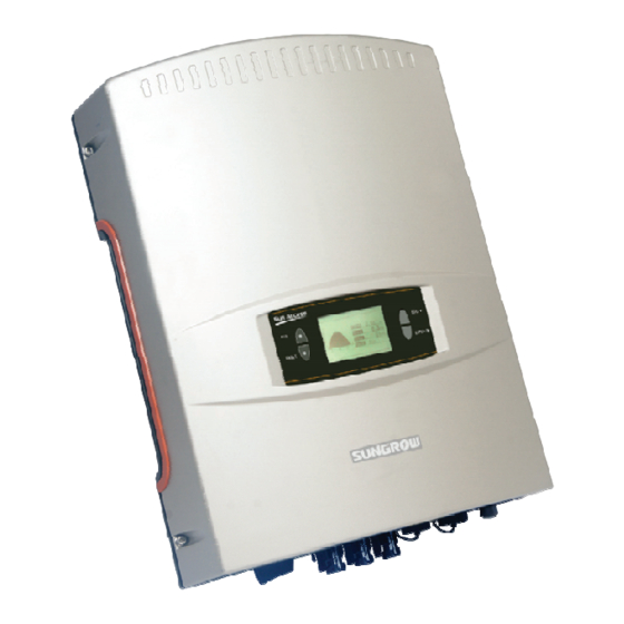
2 Product Introduction 2.1 Intended Usage SG3KTL-M, SG4KTL-M, SG4K6TL-M and SG5KTL-M (They will be referred to as inverter hereinafter unless otherwise specified), single-phase without transformer string inverter, is a crucial unit between the PV arrays and the utility grid in the small-scaled PV power system. -
Page 15: Product Description
User Manual 2 Product Introduction Any other or additional usage other than the intended usage is not permitted. Inverter only accepts PV modules of Protection Class II as its input. Inverter may only be connected to utility grid via distribution board. Local loads (home appliance, lights, motor loads, etc.) cannot be connected between the inverter and AC circuit breaker on the distribution board. -
Page 16: Dimensions And Weight Of Inverter
W(mm) H(mm) D(mm) Net weight(kg) SG3KTL-M/SG4KTL-M/ SG4K6TL-M /SG5KTL-M 2.2.3 LCD Display Panel As a human-computer interaction interface, LCD display panel comprises LED indicators, buttons and LCD display screen on inverter front panel. LEDs indicate the working status of the inverter... - Page 17 User Manual 2 Product Introduction Item Name Description They are “RUN” and “FAULT”. User can observe the two indicators to get the current state of inverter. Detailed indicators definition is shown in Tab. 2-2. LCD screen can display the current state of the inverter, LCD screen current running information, historical information and parameters to be set.
-
Page 18: Technical Description
LCD display panel. Fig. 2-5 Main Circuit Diagram of inverter The Main Circuit shown here is for SG4KTL-M, SG4K6TL-M and SG5KTL-M, there is only one string of PV arrays in input area 2 of SG3KTL-M. - Page 19 User Manual 2 Product Introduction Communication interface Standard RS485 interface for connecting other monitoring devices to the PV system is included. Protection functions include − short circuit protection − grounding insulation resistance surveillance − inverter output voltage surveillance − inverter output frequency surveillance −...
-
Page 20: Inverter Workflow
3 Inverter Workflow The following diagram shows the inverter installation flow. Please follow these procedures. Start Unpacking and Inspection Read User Manual Install Immediately? Storage Mounting Location Selection Moving Inverter Mounting the Inverter Electrical Connection Check before Commissioning Commissioning Troubleshooting Success? Fig. - Page 21 User Manual 3 Inverter Workflow Tab. 3-1 Description of Installation Flow Order Description Remark Unpacking and inspection Section 4.1 Read this manual, especially the section on “safety Chapter 1 instruction” Store the inverter unit if not installed immediately Section 4.3 Choose the best installation site Section 5.1 Move the inverter to the installation site...
-
Page 22: Unpacking And Storage
4 Unpacking and Storage 4.1 Unpacking and Inspection The unit is thoroughly tested and strictly inspected before delivery. Although sturdy packaging is used, damages may still occur during shipping. Check the packing for any visible damages upon receiving. Check the inner contents for damage after unpacking. Check the completeness of the delivery contents according to the supplied packing list. -
Page 23: Identifying Inverter
Nameplate is attached to the side of the inverter. It provides information on the type of inverter, the most important specifications, marks of certification institutions, website and serial number which are available and identified by Sungrow. GRID-CONNECTED INVERTER GRID-CONNECTED INVERTER... -
Page 24: Delivery Contents
4 Unpacking and Storage User Manual Tab. 4-1 Description of Icons on the Nameplate Icon Description Do not dispose of the inverter with the household waste. Refer to the corresponding instructions. C-tick mark of conformity. The inverter is in compliance with directives of C-tick. -
Page 25: Storage Of Inverter
If there is more than one inverter to be stored, the maximum layers for original paper packaging are five. After long-term storage or decommissioning, local installer or Service Dept. of Sungrow should perform a comprehensive test before connecting the inverter into PV power system. -
Page 26: Securing Inverter To The Wall
5 Securing Inverter to the Wall 5.1 Selecting Installation Location Selecting an optimal installation location for the inverter is decisive for its operating safety as well as its expected efficiency and service life. 1. Take the load capacity of the wall into account. The wall (such as concrete wall or metal structure) should be strong enough to hold the weight of the inverter over a long period of time. - Page 27 User Manual 5 Securing Inverter to the Wall 5. Install the unit at eye level for easy button operation and display read. 6. It is suggested that the inverter be installed vertically with upside up for good heat dissipation. 7. Never install the inverter horizontally, or with a forward tilt or with a backward tilt or even with upside down.
- Page 28 5 Securing Inverter to the Wall User Manual 9. The ambient temperature should Max. ambient range from -25°C to 60°C. The power temperature: output will reduce when the ambient +60°C temperature exceeds 45°C. Min. ambient 10. The relative humidity of chosen temperature: installation site should never exceed -25°C...
-
Page 29: Moving Inverter To Installation Site
User Manual 5 Securing Inverter to the Wall multiple inverters installation, position inverters side by side. For multi-row inverters installation, position the inverters in a staggered arrangement. 14. Do not install the inverter in a closed cabinet. Otherwise, the inverter will not operate normally. -
Page 30: Installation Procedure
5 Securing Inverter to the Wall User Manual 5.3 Installation Procedure Inverter is installed onto the wall by means of backplate in the packaging. If you don’t use the supplied backplate, you can drill holes according to its dimension below. Fig. - Page 31 User Manual 5 Securing Inverter to the Wall Concrete Wall 1. Remove the backplate and expansion bolts from the packaging. 2. Place the backplate onto the chosen concrete wall and adjust it until it is in a horizontal position. 3. Mark the positions to drill holes using the backplate as the template. 4.
- Page 32 5 Securing Inverter to the Wall User Manual Optional Theftproof Function Put the shackle of the padlock through the mounted eye of the backplate and close the lock. The padlock should observe the following requirements: The theft protection is optional. You shall lock the inverter to the mounted eye plate of the backplate with a suitable (stainless, secured shackle and lock cylinder) padlock.
- Page 33 User Manual 5 Securing Inverter to the Wall Fig. 5-3 Fasten the Backplate to Metal Frame Item Description Remark Hexagonal socket nut Spring washer ------ Washer ------ Hexagonal bolt M10*45 Metallic wall ------ Backplate ------ 6. Lift up the inverter above the backplate with the help of other people and then slide it down to make sure that the two recesses on the back of the inverter fit perfectly with the backplate, as Fig.
- Page 34 5 Securing Inverter to the Wall User Manual The theft protection is optional. You shall lock the inverter to the mounted eye plate of the backplate with a suitable (stainless, secured shackle and lock cylinder) padlock. You must ensure that the key is available at all times for possible service purposes.
-
Page 35: Electrical Connection
6 Electrical Connection 6.1 General Safety Instruction Once the inverter is firmly attached to the appropriate location, it can be connected into the PV power system. Prior to any electrical connection, keep in mind that the inverter has dual power supplies. -
Page 36: Terminals Description
Fig. 6-1 Terminals Description * Image shown here is for reference only. Actual product you receive may differ. Tab. 6-1 Terminals Specification Terminals SG3KTL-M SG4KTL-M/SG4K6TL-M/SG5KTL-M DC1: DC input area 1, DC1: DC input area 1, one pair of input pair input terminals. -
Page 37: Overview Of Electrical Connection
SolarInfo logger User can order it from Sungrow. User equips this device to monitor the state of Remote PC the inverter. User can order it from Sungrow for wireless SolarInfo WiFi communication. SG3KTL-M: two input areas with two pairs of terminals. -
Page 38: Connecting Inverter To Ac Grid
Inverter Type Specification Recommended of AC Circuit Breaker SG3KTL-M SG4KTL-M SG4K6TL-M SG5KTL-M It is not allowed for several inverters to use the same circuit breaker. It is not allowed to connect loads between the inverter and the circuit breaker. - Page 39 User Manual 6 Electrical Connection Requirements of Inverter Parallel Grid Connection If several inverters are operated in parallel connection with the grid, there are different requirements according to different scenarios. Scenario 1: Several inverters are operated in parallel connection with the single-phase Low Voltage grid.
- Page 40 6 Electrical Connection User Manual Requirements: The sum of all inverters in parallel connection is limited to thirty. n(L1)+n(L2)+n(L3)≤30. Inverters should be distributed as equally as possible between the three phases at the low-voltage side with a maximum unbalanced load of 4.6kVA. The nominal voltage on the low-voltage side of transformer must meet the inverter output electrical specification.
-
Page 41: Assembling Ac Cables To Connector
Conductor Cross Section(mm2) Outer cable diameter(mm) Range Recommended Value Range Recommended Value SG3KTL-M 4…6 10…14 SG4KTL-M 4…6 10…14 SG4K6TL-M 4…6 10…14 SG5KTL-M 4…6 10…14 Withstand ambient temperature; Layout type (inside wall, underground, free air etc.); UV resistance and so on. - Page 42 6 Electrical Connection User Manual Assembling Procedure Step 1: Unscrew the water-proof terminal. Step 2: Insert appropriately sized AC cables through the water-proof terminal. Step 3: Strip off insulation layer of all AC cables. The length of stripped insulation is approximately 10mm.
-
Page 43: Ac Wiring Procedure
User Manual 6 Electrical Connection 6.4.3 AC Wiring Procedure Make sure that none of the DC or AC cables connected to the inverter is live before the electrical work. Danger to human life due to high voltage existing inside the inverter! Do not turn on the AC side circuit breaker until all inverter electrical connections have completed. -
Page 44: Connecting Inverter To Pv Arrays
(see “10.14.3 PV Configuration Mode Setting”). You may see technical information “String inverters’ work mode selection criteria and configuration” in the Sungrow website to decide the PV configuration mode for inverter There is a risk of inverter damage! The following requirements should be met, otherwise they will lead to loss of any or all warranty rights. - Page 45 SG3KTL-M 3200W 550V 3200W 3000W SG4KTL-M 4300W 550V 3500W 3000W SG4K6TL-M 4950W 550V 3500W 3000W SG5KTL-M 5400W 550V 3500W To avoid input power unbalance of the two inputs or input load-restriction, ensure the two PV input cables are of the same model.
- Page 46 Limit for Each Input Current Limit SG3KTL-M 3200W 550V SG4KTL-M 4300W 550V SG4K6TL-M 4950W 550V SG5KTL-M 5400W 550V To avoid input power unbalance of the two inputs or input load-restriction, ensure the two PV input cables are of the same model.
-
Page 47: Assembling Dc Cable To Connector
Same with SG4KTL-M/ 2.5...6mm 5…8mm 550 V short-circuit SG4K6TL-M/ current. SG5KTL-M DC Connector Assembling Procedure: Unscrew the water-proof terminal in the following direction. Step 1 Strip off insulation layer of DC cable. The length of stripped insulation is Step 2 approximately 15mm. - Page 48 6 Electrical Connection User Manual Make sure that the stripped cable pin is correctly positioned. Step 4 Push down and click the spring clamp. Step 5 Insert and click the cable clamp into the connector. Step 6 Tighten the water-proof terminal with a torque ≥ 2N m via spanner (15). Step 7 For further assembly and connection instruction, please visit the webpage of the device manufacturer.
-
Page 49: Dc Wiring Procedure
User Manual 6 Electrical Connection 6.5.3 DC Wiring Procedure Make sure that none of the DC or AC cables connected to the inverter is live before the electrical work. Connect the inverter to PV array as the following procedures: Rotate the optional DC switch at the bottom to the “OFF” position. Step 1 Check the connection cable of PV string for the correct polarity and that the Step 2... - Page 50 6 Electrical Connection User Manual * Image shown here is for reference only. Actual product you receive may differ. Connect the other two PV strings with the same procedures if necessary. Step 4 Unused DC terminals should be sealed.
-
Page 51: Grounding Of Inverter
User Manual 6 Electrical Connection 6.6 Grounding of Inverter Because of the transform-less design of the inverter, DC positive pole and DC negative pole are not permitted to be grounded. A permanent destroy to the inverter may follows if otherwise. All non-current carrying exposed metal parts of the equipment and other enclosures in the PV power system should be grounded (e.g., PV arrays frame and inverter enclosure). -
Page 52: Second Protective Earth Terminal
6 Electrical Connection User Manual 6.6.1 Second Protective Earth Terminal The inverter is equipped with second protective earth terminal as specified in EN 50178. Second PE Terminals There is a second PE terminal on one side of the inverter. Users may choose to connect PE connection. -
Page 53: Communication Cable Connection
User Manual 6 Electrical Connection 6.7 Communication Cable Connection 6.7.1 Communication System Inverter provides two communication interfaces-RS485 and WiFi, and various communication methods. Where there is only one inverter, the communication connection between the inverter and PC can be established via WiFi or a RS485 cable. Where there are more than one inverter, all inverters can be connected to PC in daisy chain. - Page 54 6 Electrical Connection User Manual For Single Inverter Specification Communication via WiFi only Communication via RS485 on RJ45 terminal Communication via RS485 on 5 core terminal...
- Page 55 RJ45 terminal 5-core terminal WiFi 120Ω White-green Shielding layer is grounded green If the communication system is equipped with SolarInfo Logger, inverters may be remotely monitored via SolarInfo Bank. You may order SolarInfo Logger and/or SolarInfo Bank from the Sungrow.
-
Page 56: Communication Connection
Unscrew the adaptor from SolarInfo WiFi in the following direction. Step 1 Screw the adaptor to RS485/WiFi connector with appropriate torque. Step 2 Connect SolarInfo WiFi to the 5-pin terminal by plugging-in and tightening Step 3 the cable gland. You may order and purchase SolarInfo WiFi from Sungrow. - Page 57 User Manual 6 Electrical Connection RS485 connection on 5-pin terminal The 5 pins of the terminal are defined as below. Connector assembling and connecting procedures: Unscrew the water-proof terminal. Step 1 Lead the twist-pair shielding cable through cable gland. Step 2 Weld the cables to the pins.
- Page 58 6 Electrical Connection User Manual RS485 connection on RJ45 terminal Insert the RJ45 plug into the front plug connector until it makes a clicking Step 1 sound, install the plastic rings then tighten the cable gland with appropriate torque. Insert connector of one cable end into RS485 5-pin terminal on the bottom Step 2 of the inverter.
- Page 59 User Manual 6 Electrical Connection SolarInfo logger and RS485-232 converter are optional parts and can be ordered from Sungrow.
-
Page 60: Commissioning
Commissioning 7.1 Verify before Commissioning Before starting up the inverter, you should check the following items. 1. Inverter unit is accessible for operation, maintenance and service. 2. Re-check whether the inverter is firmly secured to the wall. 3. Room for ventilation is provided for one inverter or more than one inverter. 4. - Page 61 User Manual 7 Commissioning If inverter’s commissioning fails, “FAULT” indicator will be lit. “ ” in the LCD screen will display the type of fault. The fault must be removed before repeating from step1 to step 4. If inverter‘s commissioning succeeds, “RUN” indicator will be lit. “ ”...
-
Page 62: Disconnecting, Dismantling And Disposing Of The Inverter
8 Disconnecting, Dismantling and Disposing of the Inverter 8.1 Disconnecting the Inverter For maintenance or other service work, the inverter must be switched off. Proceed as follows to disconnect the inverter from the AC and DC power source. Lethal voltages or damages to the inverter will follow if otherwise. Disconnect the external AC circuit breaker and prevent it from reconnecting. -
Page 63: Dismantling The Inverter
User Manual 8 Disconnecting, Dismantling and Disposing of the Inverter For further disconnection and conductor reconnection instruction, please visit the webpage of device manufacturer. 8.2 Dismantling the Inverter Refer to Chapter 6 for the inverter disconnection of all cables in reverse steps. There is a risk of burn injuries and electric shock! Wait at least 10 minutes after disconnecting the inverter from the utility grid and the PV input before touching any inner live parts. -
Page 64: Troubleshooting And Maintenance
4. Check whether the voltage of DC input exceeds the inverter start-up voltage. 5. If all above conditions are OK, please contact Sungrow. 1. A fault is not removed yet. “Fault” indicator is 2. Perform troubleshooting according to the fault type in LCD lit. - Page 65 3. If the grid voltage is within the The grid voltage exceeds permissible range, contact Sungrow the allowable maximum Vac-high Service Dept.. threshold of the installation country. 1. Check the frequency of the grid.
- Page 66 PV arrays. 2. Check the grounding/PE connection Earth-ft Earth fault. of the inverter. 3. Contact Sungrow Service Dept. for solution. 1. Rotate the optional DC switch to the “OFF” position immediately. 2. Measure the short-circuit current of PV1 string again. Decrease the number...
- Page 67 Wait a moment for inverter The AC output current is Iac-high recovery. too high. If the fault occurs repeatedly, contact Sungrow Service Dept. for solution. Contact Sungrow Service Dept. for Fan-flt Fan’s defect. solution. DC injection of inverter Contact Sungrow Service Dept. for...
-
Page 68: Maintenance
9 Troubleshooting and Maintenance User Manual 9.3 Maintenance 9.3.1 Routine Maintenance Items Methods Period Save the running data, parameters and Save data Once a month log to a disk or a file. Visual check any damage or deformation of the inverter. Check any abnormal noise during the running of the inverter. -
Page 69: Fan Cleaning And Replacement
User Manual 9 Troubleshooting and Maintenance 9.3.2 Fan Cleaning and Replacement Disconnect the inverter from the grid first and then PV arrays before any maintenance work. Lethal voltage still exists in the inverter. Please wait at least ten minutes and then perform maintenance work. Fans’... -
Page 70: Operation Of Lcd Menu
10 Operation of LCD Menu 10.1 Button Function Inverter offers two buttons for user to look up the running information and configure parameters. User should know the button function and operation before any work on the inverter. Tab. 10-1 Description of Button Function Button Operation Description... -
Page 71: Overview Of Lcd Menu
User Manual 10 Operation of LCD Menu 10.2 Overview of LCD Menu Fig. 10-1 Menu Tree... -
Page 72: The Default Screen
10 Operation of LCD Menu User Manual 10.3 The Default Screen The LCD is initialized when the inverter is energized delay 5 seconds and then enters into the default menu. The default screen displays basic running information. “P-ac” means the current output power of the inverter. -
Page 73: Current Running Information Checking
User Manual 10 Operation of LCD Menu 10.5 Current Running Information Checking 1. Long press “ENTER/►” to enter into the general control screen. ▼ to view the current 2. Short press “ESC/ ” ▼ to turn running information. Short press “ESC/ ” pages. -
Page 74: Historical Information Checking
10 Operation of LCD Menu User Manual 10.6 Historical Information Checking 10.6.1 Running Record Checking Inverter archives the running information every fifteen minutes during inverter operation. User can view the historical running records by the following procedures. 1. Long press “ENTER/►” to enter into the general P(%) control screen. -
Page 75: Fault Record Checking
User Manual 10 Operation of LCD Menu 10.6.2 Fault Record Checking Inverter archives the types of malfunctions and the duration of malfunctions during inverter operation. User can view the historical fault records by the following procedures. 1. Long press “ENTER/►” to enter into the P(%) general control screen. -
Page 76: Language Setting
10 Operation of LCD Menu User Manual 10.7 Language Setting Input the correct password of 1111 to set the inverters' parameters. There are system parameters, running parameters, protective parameters and communication parameters to be set. Inverter supports four different languages: English, German, French and Italian. Language can be configured as follows. -
Page 77: Time Setting
User Manual 10 Operation of LCD Menu 10.8 Time Setting Deviation from the local time will directly affect the data logging. Perform the “set time” operation if necessary. 1. Long press “ENTER/►” to enter into the P(%) general control screen. 4.000 kW P-ac 15.6 kWh... -
Page 78: Energy Deviation Adjustment
10 Operation of LCD Menu User Manual 10.9 Energy Deviation Adjustment The energy yields displayed by the LCD panel are indicative only. For the actual yields, please refer to the electric energy meter. 1. Long press “ENTER/►” to enter into the general P(%) control screen. -
Page 79: Load Default
User Manual 10 Operation of LCD Menu 10.10 Load Default If you perform the “Load default” operation, all running information and historical information will be unrecoverable cleared. 1. Long press “ENTER/►” to enter into the general P(%) control screen. 4.000 kW P-ac 15.6 kWh E-day... -
Page 80: Firmware Version Checking
10 Operation of LCD Menu User Manual 10.11 Firmware Version Checking User can only view the firmware version. 1. Long press “ENTER/►” to enter into the general P(%) control screen. 4.000 kW P-ac 15.6 kWh E-day E-tot 4976 kWh State 2009/11/18 18:35 ▼... -
Page 81: Running Parameters Setting
User Manual 10 Operation of LCD Menu 10.12 Running Parameters Setting 1. Long press “ENTER/►” to enter into the P(%) general control screen. 4.000 kW P-ac 15.6 kWh E-day E-tot 4976 kWh State 2009/11/18 18:35 ▼ 2. Short press “ESC/ ” to navigate the arrow-pointer to “Set-param”. -
Page 82: Protective Parameters Setting
▼ 6. Short press “ESC/ ” to navigate the arrow-pointer to “Pro-param”. 7. Long press “ENTER/►” to enter into its sub-screen. 8. Enquire Sungrow or the dealer about the Pro-param password. Password: 000000 9. Each abbreviation represents a protective parameter. - Page 83 User Manual 10 Operation of LCD Menu 10. If you selected “Other”, Long press “ENTER/►” Vgrid-max 260V to enter into its sub-screen to set the protective Vgrid-min 195V parameter. Fgrid-max 50.2Hz Fgrid-min 49.7Hz Tab. 10-2 Description of the Protective Parameters Code Full Name Code...
-
Page 84: Communication Parameters Setting
10 Operation of LCD Menu User Manual 10.14 Communication Parameters Setting The inverter can be remotely monitored and controlled. The communication parameters of the inverter should be configured before connecting to upper computer as follows: 10.14.1 Address Setting 1. Long Press “ENTER/►” to enter into the general P(%) control screen. -
Page 85: Wireless Address Setting
User Manual 10 Operation of LCD Menu 10.14.2 Wireless Address Setting 1. WiFi configuration icon will appear on the LCD screen automatically 30s after the LCD is energized. 2. If you succeed in configuring WiFi, it will automatically connect to the Router selected. 3. - Page 86 10 Operation of LCD Menu User Manual ▼ 10. Short press “ESC/ ” to navigate the arrow-pointer to “Com-param”. 11. Long press “ENTER/►” to enter into its sub-screen. ▼ 12. Short press “ESC/ ” to navigate the arrow-pointer to “RF Address”. 13.
-
Page 87: Pv Configuration Mode Setting
User Manual 10 Operation of LCD Menu 10.14.3 PV Configuration Mode Setting 1. Long Press “ENTER/►” to enter into the general P(%) control screen. 4.000 kW P-ac 15.6 kWh E-day E-tot 4976 kWh State 2009/11/18 18:35 ▼ Short press “ESC/ ” navigate arrow-pointer to “Set-param”. -
Page 88: Inverter Start/Stop
10 Operation of LCD Menu User Manual 10.15 Inverter Start/Stop Starting the Inverter 1. Long press “ENTER/►” to enter into the general P(%) control screen. 4.000 kW P-ac 15.6 kWh E-day E-tot 4976 kWh State 2009/11/18 18:35 ▼ Short press “ESC/ ”... -
Page 89: Appendix
11 Appendix 11.1 Technical Data 11.1.1 Electrical Speci cations Technical SG4K6TL- SG3KTL-M SG4KTL-M SG5KTL-M Speci cations Input Side Data Nominal input 370V voltage … MPP voltage range for 160…500V 170…500V 195…500V 200…500V nominal power Max. input 3200W(3200 4300W(3000 4950W(3000 5400W(3000 power(DC1/DC2) W/3200W) W/3500W) - Page 90 Technical SG4K6TL- SG3KTL-M SG4KTL-M SG5KTL-M Specifications Nominal grid 50Hz/60Hz frequency 45Hz…55Hz/55Hz…65Hz (May vary as per corresponding Grid frequency range country’s grid standard) <3% (Nominal power) DC current injection <0.5% >0.99@default value at nominal power * (adj. 0.8 over-excited~0.8 under-excited) Power Factor *Valid only when the Pro-param on the LCD display is set as DE Protection...
- Page 91 Technical SG4K6TL- SG3KTL-M SG4KTL-M SG5KTL-M Specifications IEC61000-6-2, IEC61000-6-3 AS/NZS3100, AS4777.2, AS4777.3 VDE-AR-N-4105* Certification * SG4K6TL-M is not certificated in Australia SG5KTL-M is not certificated by TÜV Mechanical Data Dimensions(W×H×D) 420×555×179mm Mounting method Wall bracket Weight 24kg...
-
Page 92: Pv Input Specification
Short-circuit Power Input Voltage Limit Current Limit Limit for Power for Each Input Each Limit Input 3200W SG3KTL-M 3200W 550V 3200W 3000W SG4KTL-M 4300W 550V 3500W 3000W SG4K6TL-M 4950W 550V 3500W 3000W SG5KTL-M 5400W 550V 3500W 11.1.3 Temperature Derating Curve... -
Page 93: Exclusion Of Liability
Unforeseen calamity or force majeure The use of supplied software produced by Sungrow Power Supply Co., Ltd. is subject to the following conditions: Sungrow Power Supply Co., Ltd. assumes no liability for direct or indirect damages arising from the use of SolarInfo software. -
Page 94: About Us
The power rating of Sungrow products covers from several hundred watt to large mega-watt systems. The pursuit of Sungrow is to help our customers acquire stable and clean power with minimum cost, maximum reliability and enhanced safety. Contact Information Should you have any questions or queries about this product, please contact us through the following information. - Page 95 Sungrow Power Supply Co., Ltd. Add: No.1699 Xiyou Rd.,New & High Technology Industrial Development Zone, 230088,Hefei, P. R. China. Post Zip: 230088 Web: www.sungrowpower.com Tel: +86 551 6532 7834/6532 7845 E-mail: info@sungrow.cn Fax: +86 551 6532 7856 Specifications are subject to changes without advance notice.
Need help?
Do you have a question about the SG4K6TL-M and is the answer not in the manual?
Questions and answers