Table of Contents

Related Manuals for Sungrow SG1100UD-MV


Summary of Contents for Sungrow SG1100UD-MV
- Page 1 System Manual MV Grid-Connected Inverter SG1100UD-MV/SG3300UD-MV/SG4400UD-MV/ SG4400UD-MV-20 SG1100UD-MV/ SG3300UD-MV/SG4400UD-MV/ SG4400UD-MV-20MV Grid- Connected InverterSystem ManualSG1100_3300_4400UD-MV- 20-SEN-Ver22-202302M-D-000459 SG1100_3300_4400UD-MV-20-SEN-Ver22-202302...
-
Page 3: All Rights Reserved
Software Licenses • It is prohibited to use data contained in firmware or software developed by SUNGROW, in part or in full, for commercial purposes by any means. • It is prohibited to perform reverse engineering, cracking, or any other operations that... -
Page 5: Table Of Contents
Contents All Rights Reserved .....................I 1 About This Manual ...................1 1.1 Validity......................1 1.2 Target Group ....................1 1.3 How to Use This Manual .................1 1.4 Symbol Explanations ..................2 2 Safety Instructions ....................3 2.1 Unpacking and Inspection ................4 2.2 Hoisting and Transportation................4 2.3 Electrical Connection ..................5 2.4 Operation.......................6 2.5 Operation and Maintenance ................6... - Page 6 5.3 Installation Environment Requirements ............21 5.3.1 Installation Site ...................21 5.3.2 Foundation ..................21 5.3.3 Installation Spacing ................22 5.4 Hoisting and Fixing ..................22 5.4.1 Preparation Before Hoisting ..............22 5.4.2 Requirements for hoist and lifting rope ..........23 5.4.3 During Hoisting ...................23 5.4.4 Fastening of Connectors..............24 5.4.5 Fixing ....................25 6 Electrical Connection ..................27...
- Page 7 7 Powering up and Powering down ..............44 7.1 Safety Instructions ..................44 7.2 Powering Up Operations ................44 7.2.1 Removing Film on Product..............44 7.2.2 Removing Pressure Relief Screw ............45 7.2.3 Installing Fuse in AC SPD ..............45 7.2.4 Adjusting De-energized Tap Changer ...........46 7.2.5 Opening Pressure Relief Valve.............46 7.2.6 Removing Foam Part from Oil Thermometer .........47 7.2.7 Draining Oil from Transformer ..............47...
- Page 8 9 Troubleshooting ....................58 9.1 Inverter Troubleshooting ................58 9.1.1 Viewing Fault/Alarm Information............58 9.1.2 Check Method ..................58 9.2 Other Faults ....................70 10 Routine Maintenance ..................72 10.1 Safety Instructions ..................72 10.2 Maintenance Period ..................74 10.2.1 Maintenance (Once Every Three Years)..........74 10.2.2 Maintenance (Every two years) ............75 10.2.3 Maintenance (Once A Year) ...............76 10.2.4 Maintenance (Every half a year to once a year) ........77 10.3 Common Maintenance Items ...............78...
-
Page 9: About This Manual
This manual describes the transportation and storage, mechanical installation, electrical connection, power up and shutdown, web operation, troubleshooting, and maintenance of the MV grid-connected inverter. Validity This manual applies to the following models: • SG1100UD-MV • SG3300UD-MV • SG4400UD-MV •... -
Page 10: Symbol Explanations
1 About This Manual System Manual version upgrade, and the actual product shall prevail. For any questions, please contact Sungrow Customer Service. Symbol Explanations To ensure the safety of the users and their properties when they use the product and to make sure that the product is used optimally and efficiently, this manual provides users with the relevant safety information which is marked by the following symbols. -
Page 11: Safety Instructions
Perform operations considering ac- tual onsite conditions. • SUNGROW shall not be held liable for any damage caused by violation of gen- eral safety operation requirements, general safety standards, or any safety in- struction in this manual. -
Page 12: Unpacking And Inspection
If there are problems with the above inspection items, do not install the product and contact SUNGROW in time. Hoisting and Transportation Risk of personal injury or device damage due to incorrect operation! •... -
Page 13: Electrical Connection
System Manual 2 Safety Instructions Electrical Connection Before electrical connections, please make sure that the product is not damaged. Otherwise, it may cause danger! Before electrical connections, please make sure that the product switch and all switches connected to the product are set to "OFF", and use measuring equipment to ensure that there is no voltage at the connection. -
Page 14: Operation
2 Safety Instructions System Manual Before connecting the PV module to this product, check and confirm the polarity correctness of the PV module, and then connect it to the corresponding position of this product. During the installation and operation of the product, please ensure that the positive or negative polarities of PV strings do not short-circuit to the ground. - Page 15 To avoid the risk of electric shock, do not perform any other maintenance opera- tions beyond those described in this manual. If necessary, contact SUNGROW for maintenance. Otherwise, the losses caused are not covered by the warranty.
-
Page 16: Disposal
2 Safety Instructions System Manual To prevent misuse or accidents caused by unrelated personnel, post prominent warning signs or demarcate safety warning areas around the device to prevent ac- cidents caused by misuse. Disposal Please scrap the inverter in accordance with relevant local regulations and stan- dards to avoid property losses or casualties. -
Page 17: Product Description
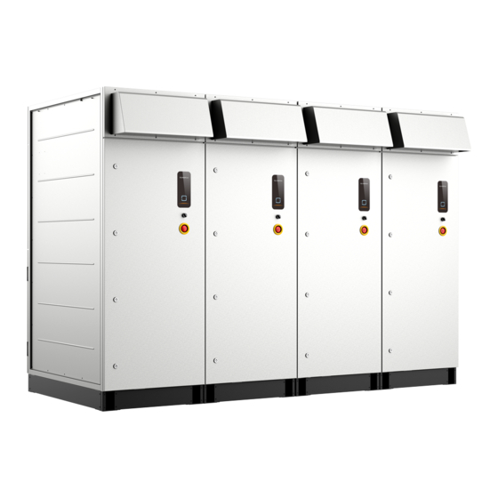
Product Description Product Introduction In large and medium-sized utility power plant systems, the MV grid-connected inverter, which contains multiple PV inverter units, transformers, and other equipment, provides a sound solution to convert the DC power generated by PV arrays into AC power, and feed it into the grid. - Page 18 3 Product Description System Manual * The figure is for reference only. And the actual product received shall prevail. Name Description Convert the DC power generated by PV modules Inverter units into AC power. Convert the low-voltage AC power output by inver- Transformer ter units into medium-voltage AC power.
-
Page 19: Main Internal Equipment
System Manual 3 Product Description Main Internal Equipment 3.3.1 Appearance of Inverter Unit Name Top front air outlet and back inlet Indicator panel Start/Stop knob Emergency stop button. In case of emergency, press this button to discon- nect the electrical connection inside the product. Bottom and side front air outlet and back inlet Base LED Indicator... -
Page 20: Internal Structure Of Inverter Unit
3 Product Description System Manual Description Color Status A fault occurred and the system cannot be con- Steady on nected to the grid for power generation. Blinking (Interval WiFi connection is established and data communi- 0.2s) cation is in process. A fault is detected. The AC and DC power are disconnected. -
Page 21: Main Parts Of Transformer
System Manual 3 Product Description Description Name DC wiring copper bar Control the on/off of the AC side circuits of the AC circuit breaker QF1 inverter. AC wiring copper bar Connected with transformer Disconnect it before maintenance and repair. Maintenance switch Q1 Fuse of AC side SPD 3.3.3 Main Parts of Transformer The transformer is equipped with multiple protective devices such as the oil temperature... -
Page 22: Main Parts Of Power Distribution Cabinet
3 Product Description System Manual Description Graphics Name When a fault occurs inside the transformer, a large amount of gas is generated, and the pressure of the insulating oil rises sharply. This valve automati- Automatic pres- cally opens to drain the oil when the pressure sure relief valve reaches the threshold, so that the internal pressure of the transformer can be rapidly reduced to a nor-... - Page 23 System Manual 3 Product Description figure 3-1 Main Parts of 5K Power Distribution Cabinet Description QS4, main switch Ethernet port Wiring terminal block and micro circuit breaker figure 3-2 Main Parts of 15–40K Power Distribution Cabinet Description Ethernet port QS4, main switch Wiring terminal block and micro circuit breaker * The figure is for reference only.
-
Page 24: Symbol On Products
3 Product Description System Manual Symbol on Products Explanation Marks Comply with CE certification. High voltage inside! Risk of electric shock by touching it! The temperature here is beyond the acceptable range for the hu- man body, please do not touch it arbitrarily to avoid personal injury. -
Page 25: Transport And Storage
Transport and Storage Precautions Failure to transport and store the product in accordance with the requirements in this manual may invalidate the warranty. Transportation Requirements • Choose appropriate means of transportation according to the size and weight of the product. •... - Page 26 4 Transport and Storage System Manual • Avoid storage for more than three months. If the product is stored for too long, be sure to take strict protective measures and carry out the necessary inspection. Open the product door first to visually check the product and internal equipment for damage. If the product is stored for more than a year, check it after it is powered on and starts.
-
Page 27: Mechanical Mounting
If there are pro- blems with the above inspection items, do not install the product and contact SUNGROW in time. -
Page 28: Inspection Before Installation
5 Mechanical Mounting System Manual Improper hoisting may cause personal injury! • It is strictly prohibited to stand within 5m - 10m outside the operating area (i.e., under the boom and the hoisted machine) to avoid casualties. • Only professional personnel can operate the product, and be sure to wear per- sonal protective equipment when operating. -
Page 29: Product Inspection
• Visually check the product for any damage. If any problems are found or there is any question, please contact the forwarding company or SUNGROW. Only install the product when it is complete and intact. Before installation, ensure that: •... -
Page 30: Installation Spacing
5 Mechanical Mounting System Manual • Pre-bury the threading pipe at the bottom of the foundation according to the location of the cable inlet holes at the bottom of the product. • A drainage system is necessary to prevent the bottom or internal equipment of the pro- duct from being soaked in water during the rainy season or during heavy rainfall. -
Page 31: Requirements For Hoist And Lifting Rope
System Manual 5 Mechanical Mounting 5.4.2 Requirements for hoist and lifting rope Requirement Cranes Rated load Four lifting ropes of equal length, the length of a single rope Lifting Ropes is not less than 6.5m. The load that a single rope can bear is not less than 7t. 5.4.3 During Hoisting •... -
Page 32: Fastening Of Connectors
5 Mechanical Mounting System Manual figure 5-2 SG4400UD-MV Hoisting Diagram Be sure to hoist the product smoothly and evenly to avoid collision and vibration. Do not turn the product upside down, nor hoist it for a long time. Otherwise, perso- nal injury or product damage may occur! 5.4.4 Fastening of Connectors Use slings with hooks or U-hooks to hoist the MV Station. -
Page 33: Fixing
• National and local safety rules should be observed at all times. • Regardless of relevant safety rules may void pertinent warranty claims from Sungrow. 5.4.5 Fixing Hoist the product to the intended location and fix it. Fixed by Welding Secure the bottom of the product to the foundation by welding. - Page 34 5 Mechanical Mounting System Manual The steps to fixing the L mounting parts is shown in the following figure.
-
Page 35: Electrical Connection
Electrical Connection Precautions • Before electrical connections, please make sure that the inverter is not da- maged, otherwise, it may cause danger! • Before electrical connections, please make sure that the product switch and all switches connected to the product are set to "OFF", and use measuring equip- ment to ensure that there is no voltage at the connection. -
Page 36: Wiring Overview
6 Electrical Connection System Manual Damage to the device caused by incorrect wiring is not covered by the warranty. • Electrical connection must be performed by professional personnel who wear personal protective equipment. • The cables used in the PV generation system must be firmly connected, in good condition, and well insulated to appropriate sizes. -
Page 37: Preparation Before Wiring
System Manual 6 Electrical Connection 1- Inverter 2– Transformer 3– Power Distribution Cabinet table 6-1 Interface Description Description Recommended Cable Specifications DC input port 400 mm at most AC output port 70 mm — 400 mm shielded twisted pair cable Communication port 2 x 0.75 mm External power supply... -
Page 38: Open The Product Door
6 Electrical Connection System Manual Torque screwdriver Wire stripper Hydraulic clamp Heat gun Torque wrench Multimeter Electric drill Screwdriver Protective gloves Goggles Insulated shoes Protective clothing Hard hat 6.3.2 Open the Product Door step 1 Open the cabinet door. step 2 Fix the doors of the inverter unit cabinet and power distribution cabinet. step 3 Remove the protective cover of the wiring area. -
Page 39: Cables
System Manual 6 Electrical Connection 6.3.3 Cables The cables must meet the following requirements: • The current carrying capacity of the cable should meet the requirements. Factors affect- ing the current-carrying capacity of a conductor include but are not limited to: –... -
Page 40: Ground Connection
AC cables, DC cables, and communication cables. • Both grounding terminals on the side of the product must be connected to the protective grounding points reliably. SUNGROW shall not be held liable for any damage caused by the violation. -
Page 41: Overview
System Manual 6 Electrical Connection Note the following during ground connection: • Observe specific codes and regulations of the country/region where the project is located to perform ground connections. • All grounding connections inside the PV system must be secure and reliable. •... -
Page 42: Dc Input Connection
6 Electrical Connection System Manual 1: Heat shrink tubing 2: OT/DT terminal DC Input Connection The PV string will generate lethal high voltage when exposed to sunlight. Respect all safety instructions listed in relevant documents about PV strings. • Make sure the PV array is well insulated to the ground before connecting it to the inverter. - Page 43 System Manual 6 Electrical Connection Negative Grounding figure 6-1 5-way DC input figure 6-2 6-way DC input figure 6-3 7-way DC input...
-
Page 44: Installing Insulation Board Before Connection (Optional)
6 Electrical Connection System Manual Floating Grounding figure 6-4 5-way DC input(Single hole) figure 6-5 6-way DC input * The wiring area is subject to the actual product Mark Discreption DC side negative cable connection area DC side negative cable connection area φ17 Copper bar diameter Wiring hole... -
Page 45: Procedure
System Manual 6 Electrical Connection - - End 6.5.3 Procedure step 1 Lead the cable into the wiring area through the inlet hole, and mark the cable polarity. step 2 Strip the protective layer of the cable to expose the copper core of the wire with strippers. step 3 Install the OT/DT terminal to the wire and crimp them with a crimping tool. - Page 46 6 Electrical Connection System Manual figure 6-6 Single Side Copper Wire Connection figure 6-7 Double Side Copper Wire Connection • If aluminum wires are used, fasten the bolt assembly as shown below.
-
Page 47: Ac Side Connection
System Manual 6 Electrical Connection figure 6-8 Single Side Aluminum Wire Connection figure 6-9 Double Side Aluminum Wire Connection step 5 Pull the cable back slightly after wiring to ensure that the cable is long enough. • Ensure that the selected terminal can directly contact the copper bar. If there are any problems, contact the terminal manufacturer. -
Page 48: Procedure
6 Electrical Connection System Manual • Check and ensure that the sleeves and copper bars in the wiring area in the HV compart- ment are free from damage, deformation, and fracture. 6.6.2 Procedure step 1 Lead the cable from external device through the cable entry on the bottom of the cable compartment. -
Page 49: Communication Connection
System Manual 6 Electrical Connection Should there be any unused wiring terminals, block them with insulating caps. Communication Connection 6.7.1 Overview There is an RS485 communication terminal block inside the power distribution cabinet. table 6-2 Port Mark and Definition (Example) Marks Plug-compatible Devices PVS, meteo station, electricity meter, transformer, etc. -
Page 50: Check After Wiring
6 Electrical Connection System Manual figure 6-12 Ethernet Communication Port of 5k Power Distribution Cabinet. figure 6-13 Ethernet Communication Port of 15–40K Power Distribution Cabinet. Connect external monitoring devices to the Ethernet port by a CAT-5e cable. Check After Wiring 6.9.1 Inspection Check the wiring thoroughly and carefully when all electrical connections have been completed. - Page 51 System Manual 6 Electrical Connection It is forbidden to close the door forcibly when the door is fixed. step 2 Lock the cabinet door and pull out the key. Electric shock hazard! Be sure to lock the cabinet door. Otherwise, non-professionals may be exposed to the running machine, and it may cause casualties.
-
Page 52: Powering Up And Powering Down
Powering up and Powering down Safety Instructions When the product is working: • It is strictly forbidden to touch the live parts of the product. Otherwise, an elec- tric shock may occur. • It is strictly prohibited to disassemble any parts of the product. Otherwise, an electric shock may occur. -
Page 53: Removing Pressure Relief Screw
System Manual 7 Powering up and Powering down 7.2.2 Removing Pressure Relief Screw Be sure to remove the pressure relief screw (marked as A in the figure below) before the product is officially put into operation. 7.2.3 Installing Fuse in AC SPD step 1 Open the fuse holder in the AC side. -
Page 54: Adjusting De-Energized Tap Changer
7 Powering up and Powering down System Manual - - End 7.2.4 Adjusting De-energized Tap Changer Adjust the output voltage of the transformer. When operating the de-energized tap changer, ensure that the transformer is in a non-excitation state, that is, the high and low voltage sides of the transformer are uncharged. -
Page 55: Removing Foam Part From Oil Thermometer
System Manual 7 Powering up and Powering down 7.2.6 Removing Foam Part from Oil Thermometer Remove the protective cover on the oil thermometer and remove the foam parts in the pro- tective cover before the inverter is officially put into operation. After removal, re-install the protective cover. -
Page 56: Inspection Before Powering Up
7 Powering up and Powering down System Manual step 4 Open the drain valve and the oil in the transformer slowly flows from the transformer into the tank. step 5 Check the position of the oil level gauge according to the temperature-level curve according to the local ambient temperature. -
Page 57: Pv Array
System Manual 7 Powering up and Powering down 7.3.2 PV Array The DC side voltage shall not exceed the maximum DC voltage allowed for the inverter. Otherwise, the inverter may be damaged and even cause safety accidents. To ensure the stable and efficient operation of the whole system, it is recommended that bat- teries connected to an inverter should be of the same type and from the same manufacturer, and the number of batteries connected in series should be the same. -
Page 58: Powering Down Operations
7 Powering up and Powering down System Manual step 4 Check and ensure that the “Access Protection Enabling” switch is off on the Web page. step 5 Close the output switch of the upstream PVS. step 6 Turn the DC knob switch to the “ON” position. step 7 Close the DC load switch QS1 inside all inverters. - Page 59 System Manual 7 Powering up and Powering down step 6 Turn the main switch QS4 inside the power distribution cabinet to OFF step 7 Disconnect the load switch of the inverter and the transformer and the output switch of the upstream PVS.
-
Page 60: Web Operation
WEB Operation Communications Diagram The wiring between the internal devices of the MV grid-connected inverter has been com- pleted before delivery. Connect the PC with the switch inside the power distribution cabinet with the CAT-5e cable on site. After that, the WEB interface can be accessed on a PC. figure 8-1 Wired Communication Diagram A wireless communication module is embedded inside the inverter, and the WEB interface can also be accessed through mobile devices such as mobile phones. -
Page 61: Preparation Before Login
System Manual 8 WEB Operation figure 8-2 Wireless Communication Diagram Preparation Before Login 8.2.1 Login (PC) step 1 To connect the PC to the product, connect the network cable to the network port of the PMD switch. step 2 Configure the IP address of the PC. Set the IP address of the PC to the same network seg- ment as the NET1 address of the smart unit board. -
Page 62: Interface Introduction
8 WEB Operation System Manual • NET1 port, URL: 14.14.14.14. • NET2 port, URL: 12.12.12.12. Mobile device: URL:11.11.11.1. step 2 Click and select the desired language in the upper right corner of the interface. step 3 Click to enter the login interface. step 4 Enter the password and click Login to enter the interface as a general user. -
Page 63: Viewing Fault Information
System Manual 8 WEB Operation 8.4.2 Viewing Fault Information step 1 Click “Overview” → “General Information” on the left navigation bar to enter the homepage. step 2 Click in the upper-right corner of the interface to view information such as the name and time of the fault event. -
Page 64: Setting System Parameters
8 WEB Operation System Manual step 2 Select a device in the left device list in the function display area. Click “Operation Para- meters” on the right. enter a value in “Current Value”, and then click “Settings” Click “Configure Synchronization”to synchronize the settings to other devices of the same type. -
Page 65: Logout
System Manual 8 WEB Operation Logout To protect the account security, it is recommended to log out in time after the operation is completed. Exit Method Click and select Logout in the upper right corner of any interface. -
Page 66: Troubleshooting
Whether the emergency stop button is pressed • Whether the inverter limits the output of active power If the problem still persists or there are any other questions, please contact SUNGROW. It would be helpful if the following information is provided during a call: •... - Page 67 System Manual 9 Troubleshooting Fault Name Fault Cause Fault Level Corrective Method 1. Check whether a short circuit occurs on the AC or DC sides of The drive board the inverter. generates a fault 2. Check the grid for any Important Module fault signal or a hard-...
- Page 68 9 Troubleshooting System Manual Fault Name Fault Cause Fault Level Corrective Method 1. Check whether the grid vol- tage is normal. 2. Check whether the control fan is normal. The temperature Control cabinet 3. Check the AC filter system. inside the control Important temperature Check whether there are ab-...
- Page 69 System Manual 9 Troubleshooting Fault Name Fault Cause Fault Level Corrective Method 1. Check whether the ambient temperature is normal; Use a thermometer to check whether the current ambient temperature is within the tem- perature range advertised by the If the temperature inverter.
- Page 70 9 Troubleshooting System Manual Fault Name Fault Cause Fault Level Corrective Method 1 Check whether the protection parameters on the interface meet the grid standards of the lo- cation where the inverter is The grid fre- Frequency fault Important installed. quency is abnormal.
- Page 71 System Manual 9 Troubleshooting Fault Name Fault Cause Fault Level Corrective Method Check whether the power grid is The inverter fails Important abnormal, such as harmonics Soft start fault to start. and voltage balance. Check the status indicator of the SPD.
- Page 72 9 Troubleshooting System Manual Fault Name Fault Cause Fault Level Corrective Method Disconnect the DC switch of the inverter and check whether the open-circuit voltage of the PV ar- rays is normal; If not, the PV ar- ray configuration may be faulty. The DC side vol- 2.
- Page 73 System Manual 9 Troubleshooting Fault Name Fault Cause Fault Level Corrective Method 1. Check the air inlet. 2. Check whether the air outlet The temperature of the inverter is blocked. Re- Module over- of modules inside place the air filter screen if Important temperature the inverter is ex-...
- Page 74 AC cabinet. Clean it if necessary. Check whether the DC fuse is The fuse on the blown. DC fuse Secondary DC side of the in- anomaly If so, please contact SUNGROW verter fails. to replace the fuse.
- Page 75 2. Check the communication terminal of the meter is loose. Check whether the DC fuse is The fuse on the blown. Secondary DC fuse fault DC side of the in- If so, please contact SUNGROW verter fails. to replace the fuse.
- Page 76 HVRT or LVRT. voltage. If the fault/alarm cannot be cleared following the above corrective methods and still persists, please contact SUNGROW directly. Fault Name Fault Cause Fault Level Corrective Method The AC switch is...
- Page 77 Fault Level Corrective Method The addresses of the inver- Machine code re- Please contact Important ter units inside the inverter petition fault SUNGROW. are the same. Temperature and The communication of the humidity board Please contact Secondary temperature and humidity communication SUNGROW.
-
Page 78: Other Faults
If the fault is not caused by the fore- going reasons and still persists, please contact SUNGROW as soon as possible. 1. Refresh the Web page manually. 2. Restart or replace the mobile de-... - Page 79 Method”. If the fault is not caused by the fore- going reasons and still persists, please contact SUNGROW as soon as possible. 1. Export data in batches multiple The amount of data ex- Fail to export measur- times.
-
Page 80: Routine Maintenance
10 Routine Maintenance 10.1 Safety Instructions Risk of inverter damage or personal injury due to incorrect service! • Disconnect the switches between the product and all power supplies before maintenance. • After the inverter is powered off for 20 minutes, measure the voltage and cur- rent with measuring equipment. - Page 81 Otherwise, damage may be caused to the product! To avoid the risk of electric shock, do not perform any other maintenance opera- tions beyond those described in this manual. If necessary, contact SUNGROW for maintenance. Otherwise, the losses caused are not covered by the warranty.
-
Page 82: Maintenance Period
10 Routine Maintenance System Manual 10.2 Maintenance Period 10.2.1 Maintenance (Once Every Three Years) Item Check method • Oil thermometer: Alarm temperature and tripping temperature. • Pressure relief valve: Check whether the pressure re- lief valve is in good contact. Monitoring and protective equipment of the transformer •... -
Page 83: Maintenance (Every Two Years)
System Manual 10 Routine Maintenance 10.2.2 Maintenance (Every two years) Item Check method Check the following items, and correct immedi- ately those failing to meet the relevant requirements: • Check whether there is any damage or deforma- tion of the inverter and internal equipment. •... -
Page 84: Maintenance (Once A Year)
10 Routine Maintenance System Manual 10.2.3 Maintenance (Once A Year) Item Check method Check the following items, and correct immediately those fail- ing to meet relevant requirements: • Check whether there are flammable objects on the top of the inverter. •... -
Page 85: Maintenance (Every Half A Year To Once A Year)
System Manual 10 Routine Maintenance Item Check method Check the following items, and correct immediately those fail- ing to meet relevant requirements: • Check whether there are flammable objects on the top of the inverter. • Check whether the welding points between the inverter and foundation steel plate are firm and if there is corrosion. -
Page 86: Common Maintenance Items
10 Routine Maintenance System Manual Item Check method Check the temperature of the heat sink and the amount of dust accumulated. Clean heat-dissipation modules with a vacuum Air inlet and outlet cleaner if necessary. • Carry out regular inspection for corrosion of all metal components. -
Page 87: Cleaning Lower Air Inlet And Outlet
System Manual 10 Routine Maintenance Procedure step 1 Unscrew the M5 screws at the four corners of the air inlet and outlet. step 2 Clean the air inlet and outlet with a brush. step 3 Fix the air inlet and outlet with the M5 screws with a tightening torque of 4 - 4.8 N·m. - - End 10.3.2 Cleaning Lower Air Inlet and Outlet step 1 Use screwdriver to unscrew the 7 bolts at the bottom of the protective cover. -
Page 88: Appearance Repair
10 Routine Maintenance System Manual step 4 Re-install the bottom wire mesh and side wire mesh to the cabinet door in reverse steps. - - End 10.3.3 Appearance Repair Check the appearance of the product: Case 1: Erasable traces Case 2: Indelible traces Case 3: Broken primer Check whether the protective paint sprayed on the casing of the product fell off or peeled off. - Page 89 System Manual 10 Routine Maintenance 10.3.3.2 Indelible Traces Tools Name Source Abrasive paper Cleaning cloth Water Beyond the scope of supply Alcohol Brush RAL7035 oil paint step 1 Polish the paint surface with blistering or scratches with abrasive paper for a smooth surface. step 2 Wet the cleaning cloth with water or 97% alcohol, and scrub the damaged parts to remove surface stains.
-
Page 90: Checking Door Locks And Hinges
10 Routine Maintenance System Manual Name Source Brush RAL7035 oil paint step 1 Polish the damaged parts with abrasive paper to remove rust and other burrs for a smooth surface. step 2 Wet the cleaning cloth with water or 97% alcohol, and scrub the damaged parts to remove surface stains and dust. -
Page 91: Procedure
System Manual 10 Routine Maintenance step 5 Use a multimeter to measure each DC input voltage and ensure that the terminals are uncharged before performing the next operation. step 6 Replace the faulty fuse. - - End 10.4.2 Procedure step 1 Identify the faulty fuse. step 2 Use a socket wrench to unscrew the fastening bolt of the fuse to be replaced. - Page 92 10 Routine Maintenance System Manual *The image shown here is for reference only. The actual product received may differ. step 4 Close the AC side and DC side cabinet doors, and place EPE corner guards at the four top corners of the inverter. *The image shown here is for reference only.
- Page 93 System Manual 10 Routine Maintenance *The image shown here is for reference only. The actual product received may differ. Avoid rubbing the inverter against the hook or slings and bumping it with other equipment during hoisting to ensure an intact paint surface. step 6 The new inverter unit shall be installed in reverse order.
-
Page 94: Appendix
11 Appendix 11.1 Technical Parameters SG1100UD-MV/SG3300UD-MV SG1100UD-MV SG3300UD-MV Model Input (DC) Max. PV input voltage 1500 V Min. PV input voltage / 895 V / 905 V Startup input voltage MPP voltage range 895 – 1500 V No. of independent MPP... - Page 95 System Manual 11 Appendix SG1100UD-MV SG3300UD-MV Model Inverter max. efficiency / Inverter European 99.0 % / 98.7 % efficiency Transformer 1100 kVA 3300 kVA Transformer rated power Transformer max. power 1265 kVA 3795 kVA 0.63 kV / (10 – 35) kV LV / MV voltage 6.5%(0~±10%)@1100kVA...
- Page 96 11 Appendix System Manual SG4400UD-MV/SG4400UD-MV-20 SG4400UD-MV SG4400UD-MV-20 Model Input (DC) Max. PV input voltage 1500 V Min. PV input voltage / 895 V / 905 V 938 V / 950 V Startup input voltage 938 – 1500 V MPP voltage range 895 –...
-
Page 97: Tightening Torques
System Manual 11 Appendix SG4400UD-MV SG4400UD-MV-20 Model Dy11 Transformer vector ONAN (Oil-natural, air- Transformer cooling ONAN/Optional:ONAF natural) type Mineral oil (PCB free) or degradable oil on request Oil type Protection & Function Load break switch + fuse DC input protection Inverter output Circuit breaker protection... -
Page 98: Quality Assurance
• The customer shall give SUNGROW a reasonable period to repair the faulty device. Exclusion of Liability In the following circumstances, SUNGROW has the right to refuse to honor the quality guarantee: • The free warranty period for the whole machine/components has expired. - Page 99 System Manual 11 Appendix We need the following information to provide you the best assistance: • Model of the device • Serial number of the device • Fault code/name • Brief description of the problem For detailed contact information, please visit: https://en.sungrowpower.com/contactUS...
- Page 100 Sungrow Power Supply Co., Ltd. www.sungrowpower.com...
Need help?
Do you have a question about the SG1100UD-MV and is the answer not in the manual?
Questions and answers