Sungrow SG2K-S User Manual
Pv grid-connected inverter
Hide thumbs
Also See for SG2K-S:
- User manual (95 pages) ,
- Quick user manual (93 pages) ,
- Quick installation manual (22 pages)

Related Manuals for Sungrow SG2K-S


Summary of Contents for Sungrow SG2K-S
- Page 1 User Manual SG2K-S / SG2K5-S / SG3K-S/ SG3K-D / SG5K-D / SG8K-D PV Grid-Connected Inverter SG2-8K-UEN-Ver13-202003 Version:1.3...
- Page 3 Software Licenses It is prohibited to use data contained in firmware or software developed by SUNGROW, in part or in full, for commercial purposes by any means. It is prohibited to perform reverse engineering, cracking, or any other operations that compromise the original program design of the software developed by SUNGROW.
- Page 4 (PV) system. You can get additional information about other devices at www.sungrowpower.com or on the webpage of the respective component manufacturer. Validity This manual is valid for the following inverter models: SG2K-S SG2K5-S SG3K-S SG3K-D ...
- Page 5 Symbols Safety instructions will be highlighted with the following symbols. Symbol Explanation Indicates a hazard with a high level of risk that, if not avoided, will result in death or serious injury. Indicates a hazard with a medium level of risk that, if not avoided, could result in death or serious injury.
-
Page 6: Table Of Contents
Contents About This Manual ..............II Safety ..................1 PV Panels .................. 1 Utility Grid .................. 1 Inverter ..................2 Skills of Qualified Personnel ............3 Product Description ............4 Intended Use ................4 Product Introduction ..............5 2.2.1 Model Description ..............5 2.2.2 Appearance ................ - Page 7 4.2.3 Installation Angle Requirements ..........15 4.2.4 Installation Clearance Requirements ........16 Installation Tools ..............16 Installing the Inverter ............... 18 Electrical Connection ............21 Safety Instructions ..............21 Terminal Description ..............22 Cable Requirements ..............22 Additional Grounding Connection ..........23 5.4.1 Additional Grounding Requirements ........
- Page 8 7.5.1 Inputting the Password ............43 7.5.2 Setting Protective Parameters ..........44 7.5.3 Zero-export Setting ..............47 7.5.4 Adding the Existing Inverter ............. 48 7.5.5 PF Setting ................48 7.5.6 Parameter Reset ..............48 7.5.7 DRM Switch Setting ..............48 7.5.8 GND Detection ................
-
Page 9: Safety
The safety instructions in this manual cannot cover all the precautions that should be followed. Perform operations considering actual onsite conditions. SUNGROW shall not be held liable for any damage caused by violation of the safety instructions in this manual. 1.1 PV Panels PV strings will produce electrical power when exposed to sunlight and can cause a lethal voltage and an electric shock. -
Page 10: Inverter
1 Safety User Manual All electrical connections must be in accordance with local and national standards. Only with the permission of the utility grid, the inverter can be connected to the utility grid. 1.3 Inverter Danger to life from electric shocks due to live voltage Do not open the enclosure at any time. -
Page 11: Skills Of Qualified Personnel
User Manual 1 Safety Only qualified personnel can perform the country setting. Unauthorized alteration of the country setting may cause a breach of the type-certificate marking. Risk of inverter damage due to electrostatic discharge (ESD). By touching the electronic components, you may damage the inverter. For inverter handling, be sure to: ... -
Page 12: Product Description
2 Product Description 2.1 Intended Use SG2K-S / SG2K5-S / SG3K-S / SG3K-D / SG5K-D / SG8K-D, a transformerless single-phase PV grid-connected inverter, is an integral component in the PV power system. The inverter is designed to convert the direct current power generated from the PV modules into grid-compatible AC current and feeds the AC current to the utility grid. -
Page 13: Product Introduction
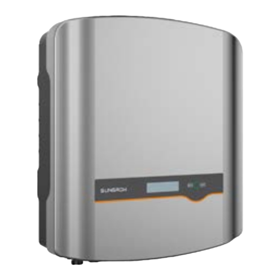
S: single MPPT, D: dual MPPTs Code of power level Code of PV grid-connected inverter Tab. 2-1 Power Level Description Model Nominal Output Power Nominal Grid Voltage SG2K-S 2000 W SG2K5-S 2500 W SG3K-S 3000 W 230 Vac (single phase) - Page 14 2 Product Description User Manual Fig. 2-2 Inverter Appearance (SG5K-D for reference) Item Name Description Positive and negative DC input connectors. PV terminals One or two or three pairs, depending on inverter model. DC switch To disconnect the DC current safely. To connect the communication module, such as RS485 terminal Wi-Fi module.
-
Page 15: Dimensions
Tab. 2-2 Dimensions and Weight Model W (mm) H (mm) D (mm) SG2K-S / SG2K5-S / SG3K-S SG3K-D / SG5K-D SG8K-D 2.2.4 LCD Panel The LCD panel with a screen, an indicator and two buttons is on the front of the inverter. -
Page 16: Function Description
You can choose the RS485 terminal for connecting a communication module to the PV system, such as Wi-Fi module. is recommended to use the communication module from Sungrow. Using a device from other companies may lead to communication failure or other unexpected damage. -
Page 17: Reactive Power Regulation
User Manual 2 Product Description Tab. 2-3 Demand Response Modes (DRMs) Mode Explanation DRM0 The inverter is in the state of standby. DRM5 The export power to the grid is 0. DRM6 The export power to the grid is no more than 50 % of the rated power. DRM7 The export power to the grid is no more than 75 % of the rated power. -
Page 18: Unpacking And Storage
Check the inner contents for damage after unpacking. Check the delivery contents for completeness according to the packaging list. Contact SUNGROW or the supplier in case there is any damage or incompleteness. Do not dispose of the original packing case. It is recommended to store the inverter in it. - Page 19 M a d e i n C h i n a Fig. 3-1 Nameplate of Inverter * The image shown here is for reference only. The actual product you receive may differ. Item Description Item Description SUNGROW logo Instructions marks product model conformity Company name,...
-
Page 20: Scope Of Delivery
3 Unpacking and Storage User Manual 3.3 Scope of Delivery Standard Delivery Wall-mounting bracket Documents Inverter Wi-Fi module M4x80 screw set Communication connector M4x10 grounding screw AC connector set PV connector set Fig. 3-2 Delivery Contents The inverter figures in this document have been created for SG5K-D unless otherwise specified. -
Page 21: Inverter Storage
User Manual 3 Unpacking and Storage 3.4 Inverter Storage Proper storage is required if the inverter is not installed immediately. Store the inverter in the original packing case with the desiccant inside. The storage temperature should be always between -30°C and +85°C, and the storage relative humidity should be always between0 and 100 %, non-condensing. -
Page 22: Mechanical Mounting
4 Mechanical Mounting 4.1 Safety during Mounting Make sure there is no electrical connection before installation. In order to avoid electric shock or other injury, be sure there is no electricity or plumbing installations before drilling holes. Risk of injury due to improper handling ... -
Page 23: Installation Environment Requirements
User Manual 4 Mechanical Mounting IP65 4.2.1 Installation Environment Requirements The installation environment is free of inflammable or explosive materials. The location should be not accessible to children. The ambient temperature and relative humidity must meet the following requirements. -
Page 24: Installation Clearance Requirements
4 Mechanical Mounting User Manual Forward tilt Backward tilt Horizontally Upside down 4.2.4 Installation Clearance Requirements Reserve enough clearance around the inverter to ensure sufficient space for heat dissipation.Clearance requirement and multiple installation: 400 mm 400 mm For multi-row installation, the distance between two adjacent rows should be at least 400 mm. - Page 25 User Manual 4 Mechanical Mounting Protective gloves Dust mask Earplugs Goggles Insulated shoes Vacuum cleaner Heat shrink tubing Installation tools (recommended) Heat gun Hammer drill Rubber mallet Drill bit: φ10 Electric screwdriver Phillips screwdriver Wire stripper Tool bit: M4 Specification: M4 Hydraulic plier Crimping tool Wrench for MC4 terminal...
-
Page 26: Installing The Inverter
4 Mechanical Mounting User Manual Wire clipper RJ45 crimping tool Flat-blade screwdriver Torx screwdriver Socket wrench TX30 Open end: 10 mm (for M6 bolts) 13 mm (for M8 bolts) 16 mm (for M10 bolts) 4.4 Installing the Inverter Inverter is installed on the wall by means of wall-mounting bracket and the expansion plug sets. - Page 27 User Manual 4 Mechanical Mounting Align the wall mounting bracket horizontally on the wall with the arrow upwards. Mark position of the drill holes. Use at least one hole on the right- and left-hand side of the wall mounting bracket. Tip: When mounting on a post, use the upper and lower central holes of the wall mounting...
- Page 28 4 Mechanical Mounting User Manual To protect the inverter from theft, you can lock it with a padlock. padlock purchased by the user if necessary. The hole diameter is about 8 mm. Remove the waterproof lid from RS485 terminal and install the communication module to the inverter.
-
Page 29: Electrical Connection
5 Electrical Connection 5.1 Safety Instructions Prior to any electrical connections, keep in mind that the inverter has dual power supplies. It is mandatory for the technical personnel to wear personal protective equipments (PPE) during the electrical work. Danger to life due to a high voltage inside the inverter ... -
Page 30: Terminal Description
AC terminal The AC terminal to the utility grid. 5.3 Cable Requirements Specification Outer Conductor Cable Inverter Model diameter Cross-section (mm) SG2K-S / SG2K5-S 10–14 4–6 / SG3K-S / SG3K-D AC cable SG5K-D 10–14 4–6 SG8K-D PV cable 6–9 4–6 Additional 4–6... -
Page 31: Additional Grounding Connection
User Manual 5 Electrical Connection (1) The AC cable must be dimensioned in accordance with the local and national directives for the dimensioning of cables. (2) The PV cables must be multi-core cables, of which the maximum withstand voltage is 600 V and the maximum withstand current is the same as the short-circuit current. -
Page 32: Ac Cable Connection
5 Electrical Connection User Manual L = E + (2~3)mm 1: Heat shrink tubing 2: OT/DT terminal Remove the screw on the grounding terminal and fasten the cable with a screwdriver. 1.5N.m Apply paint to the grounding terminal to ensure corrosion resistance. 5.5 AC Cable Connection The inverter is connected to the grid via 3 wires (L, N and PE). -
Page 33: Assembling The Ac Connector
An independent two-pole circuit breaker is installed on the output side of the inverter to ensure safe disconnection from the grid. The recommended specifications are as follows: Inverter Model Specification SG2K-S / SG2K5-S 15 A SG3K-S / SG3K-D 20 A SG5K-D... -
Page 34: Installing The Ac Connector
5 Electrical Connection User Manual Fully insert the conductors to the corresponding terminal and tighten the screws with the torque 0.8 Nm. Pull cables outward check whether they firmly installed. Observe the terminal layout on the block. Do not connect the phase wires to "PE"... -
Page 35: Dc Cable Connection
User Manual 5 Electrical Connection Align the AC connector and the AC terminal and mate them together by hand. Tighten the connector to the terminal until a “Click” is heard or felt. Connect the other ends. Connect “PE” conductor to the grounding electrode. -
Page 36: Pv Input Configuration
PV input Inverter inside Total PV Input Open-circuit Max. current for Model Power Limit Voltage Limit input connector SG2K-S 3000 W 600 V 15 A SG2K5-S 3200 W 600 V 15 A SG3K-S 4000 W... - Page 37 User Manual 5 Electrical Connection Independent Mode Each PV input operates independently and has its own MPPT. In this way, string structures of each PV input may differ from each other, including PV module type, number of PV modules in each string, angle of tilt, and installation orientation.
-
Page 38: Assembling The Pv Connector
To avoid the input power unbalance of the two inputs or input load-restriction, ensure the two PV input cables are of the same type. 5.6.2 Assembling the PV Connector SUNGROW provides corresponding plug connectors in the scope of delivery for quick connection of PV inputs. - Page 39 User Manual 5 Electrical Connection DC cables should be connected to the inverter via PV connectors which are included in the scope of delivery. To ensure IP65 protection, use only the supplied connector or the connector with the same ingress of protection. High voltage may be present in the inverter! Ensure all cables are voltage-free before performing electrical operations.
-
Page 40: Installing The Pv Connector
Check the positive and negative polarity of the PV strings, and connect the PV connectors to corresponding terminals only after ensuring polarity correctness. Arc or contactor over temperature may occur if the PV connectors are not firmly in place, and SUNGROW shall not be held liable for any damage caused. -
Page 41: Rs485Communication Connection
The RS485 terminal can also be used to connect an external RS485 device. For the pin definition and waterproof procedure, please contact SUNGROW. Failure to comply with the requirements of wiring or waterproofing will void the warranty. - Page 42 User Manual Solar switch Main Meter switch link Network Utility Sungrow meter meter grid PV strings Inverter Home Appliance Proceed as follows to connect the RS485 wires to the inverter. (Optional) If the RS485 cable is prepared by the customer, we recommend the shield twisted pair cable or shield Ethernet cable.
-
Page 43: Drm Connection
User Manual 5 Electrical Connection Loosen the screws and remove the waterproof lid from RS485|DRM terminal. Note: Retain the screws for later installation. Insert the RJ45 plug into the left (Meter) port until it makes a clicking sound. external demand response enabling device connected, secure... - Page 44 5 Electrical Connection User Manual Take out the communication connector from packaging, as shown on the right. Loosen the screws and remove the waterproof lid from RS485|DRM terminal. Note: Retain the screws for later installation. Unscrew the swivel nut from the cable gland and remove the waterproof plug from the right inlet.
- Page 45 User Manual 5 Electrical Connection Insert the RJ45 plug into the right port (DRM) until it makes a clicking sound. Secure the waterproof lid to the inverter bottom with four screws and then fasten the cable gland. Connect the other end to the external device.
-
Page 46: Commissioning
Commissioning 6.1 Inspection before Commissioning Check the following items before starting the inverter: The inverter DC switch and external circuit breaker are disconnected. The inverter should be accessible for operation, maintenance and service. Nothing is left on the top of the inverter. The inverter is correctly connected to the external devices, and the cables are routed in a safe place or protected against mechanical damage. -
Page 47: Commissioning Procedure
User Manual 6 Commissioning 6.3 Commissioning Procedure If all of the items mentioned above meet the requirements, proceed as follows to start up the inverter for the first time. Rotate the DC switch of the inverter to "ON" position. Connect the AC switch (if applicable) between the inverter and the grid. Connect the DC switch (if applicable) between the inverter and the PV string. -
Page 48: Lcd Operation
7 LCD Operation 7.1 Button Function The inverter offers two buttons with multiple functions. Please refer to the following table before any operation of the inverter. Tab. 7-1 Button function Button Operation Description Navigate up / down or change the setting values. ≤1.2 s Hereinafter referred to as “Touch ESC”. - Page 49 Whether the insolation is sufficient and the PV connection is correct. If no anomaly is found, disconnect and reconnect the DC switch and the main switch to restart. If it still does not work, contact SUNGROW.
-
Page 50: Menu Structure
7 LCD Operation User Manual Viewing the Active Error/Warning If the status on the main screen is “Error xxx”, Touch ENT to view the active error code. Error If the inverter is running with a warning, Touch ENT to view the active warning code. Only one error or warning can be displayed on Warning this screen. -
Page 51: Viewing Running Info
User Manual 7 LCD Operation 7.4 Viewing Running Info Proceed as follows to look through the detailed running information. Main Screen (Press ENT)→ Menu → Run Info (Press ENT) Scroll pages by touching ENT / ESC. E-today: 20.0kWh Vpv1: 250.0V Vpv2: 244.4V E-total:... -
Page 52: Setting Protective Parameters
7 LCD Operation User Manual 7.5.2 Setting Protective Parameters Protective parameters are designed for the threshold values that can trigger the protective function of the inverter. The threshold values are compliant with the requirements of local safety standards and the utility grid. If the protection function is triggered, the inverter will automatically disconnect from the grid with the ”Error xxx”... - Page 53 User Manual 7 LCD Operation Protection Recover Vmax-rec (230.0 V–311.0 V): Recovery value for over-voltage error. Inverter will start operating when the grid voltage falls below this value. Vmax-rec: 253.0V Vmin-rec (23.0 V–230.0 V): Vmin-rec: 205.0V Recovery value for under-voltage error. Inverter will start operating when the grid voltage is above this value.
- Page 54 Fig. 7-2 Volt-watt Response Curve (“AU” for example) Grid Protection Voltage Adjusting All Sungrow’s inverters are compliant with the standard AS/NZS 4777 related to grid protection requirements. In order to work with unstable utility grids, inverters are equipped with automatic protection voltage adjusting function (disabled by default).
-
Page 55: Zero-Export Setting
High line voltages may damage home appliances and Sungrow is not held responsible or liable for these issues. 7.5.3 Zero-export Setting Touch ENT / ESC to select and press ENT to confirm. -
Page 56: Adding The Existing Inverter
7 LCD Operation User Manual 7.5.4 Adding the Existing Inverter Rated-P: rated power of the existing inverter. Existing Inverter This function is OFF by default. If the existing inverter is set to ON, its rated power is the lower limit for export power setting. Rated-P: 2000W (0W~30000W) -
Page 57: Gnd Detection
User Manual 7 LCD Operation 7.5.8 GND Detection Touch ENT / ESC to select and press ENT to confirm. Select ON to enable the GND Detection. If the enclosure of the inverter is not grounded, the error code 106 will be shown on the main screen. The buzzer inside will sound at the same time. -
Page 58: Arc Detection
7 LCD Operation User Manual 7.5.12 Arc Detection Touch ENT to select and press ENT to confirm. Arc Self-test Clear Arc Fault 7.6 Starting/Stopping the Inverter Main Screen (Press ENT) → Menu (Touch ESC) → ON/OFF (Press ENT) Touch ENT / ESC to select and press ENT to confirm. -
Page 59: Setting The Country
User Manual 7 LCD Operation Main Screen (Press ENT) → Menu (Touch ESC) → Time (Press ENT) DD, MM, and YY stand for day, month, and year DD / MM / YY respectively. Date: 05 / 01 / 17 hh, mm, and ss stand for hour, minute, and second respectively. - Page 60 7 LCD Operation User Manual If the country code is set to “AU”, the grid company setting will appear. Touch ENT / ESC to choose the grid standard and press ENT to confirm. When the grid is set to “EE” or “EG”, the reactive power regulation will be in PF mode with the power factor of +0.90 (lagging).
-
Page 61: Viewing Device Info
User Manual 7 LCD Operation Other Parameter (Default) 10-min voltage 255.0 255.0 255.0 257.0 258.0 255.0 258.0 10-min Refer to Tab. 7-3 for the parameter explanation and range. If you (qualified personnel only) need to modify the voltage protective parameters, please refer to “Single/Multiple Protection”. 7.10 Viewing Device Info Main Screen (Press ENT) →... -
Page 62: System Decommissioning
8 System Decommissioning 8.1 Disconnecting the Inverter For maintenance or other service work, the inverter must be switched off. Proceed as follows to disconnect the inverter from the AC and DC power sources. Lethal voltages or damage to the inverter will follow if otherwise. Stop the inverter via the LCD menu. -
Page 63: Dismantling The Inverter
User Manual 8 System Decommissioning 8.2 Dismantling the Inverter Risk of burn injuries and electric shock! Do not touch any inner live parts until at least 10 minutes after disconnecting the inverter from the utility grid and the PV input. Refer to “5 Electrical Connection”... -
Page 64: Troubleshooting And Maintenance
1. Check the voltage of the grid. grid voltage exceeds Grid over-voltage. permissible range of inverter protection grid voltage parameters, ask utility grid company for exceeds the protective solution. value. (stage I) 3. If the grid voltage is within the permissible range, contact Sungrow Service Dept. - Page 65 2. Check whether AC cables are all firmly connected. Grid failure (Islanding) 3. Check whether grid is not in service. 4. If all conditions are OK and this fault still occurs in the LCD screen, contact Sungrow Service Dept.
- Page 66 Description Troubleshooting injection over-current. 1. Wait a moment for inverter recovery. current 2. If the fault occurs repeatedly, contact injection of AC current Sungrow Service Dept. exceeds upper limit. Leakage current over-current. 1. Check the PV strings for ground fault.
- Page 67 The slave DSP detects permissible range of inverter protection that the grid voltage parameters, ask utility grid company for exceeds inverter solution. allowable upper limit. 3. If the grid voltage is within the permissible range, contact Sungrow Service Dept.
- Page 68 Sungrow Service Dept. upper limit. Communication alarm 1. Wait 1 minute for inverter recovery. between master DSP 2. If the fault persists, contact Sungrow and slave DSP. Service Dept. Alarm for no inverter Contact Sungrow Service Dept. type setting.
- Page 69 Grid under-frequency. solution. The grid frequency is 3. If the grid frequency is within the below the protective permissible range, contact Sungrow Service value, which is lower Dept. than protective value of error 009.
-
Page 70: Maintenance
1. Inverter can normally be connected to the External memory grid. reading/writing 2. Power on the inverter again. If the fault warning. persists, contact Sungrow Service Dept. Abnormal communication Check whether power cable warning connections of the meter are correct. - Page 71 For any maintenance need, please contact SUNGROW. Otherwise, SUNGROW shall not be held liable for any damage caused. Servicing of the device in accordance with the manual should never be undertaken in the absence of proper tools, test equipments or the latest revision of the manual which has been clearly and thoroughly understood.
-
Page 72: Appendix
10 Appendix 10.1 Technical Data 10.1.1 –S Series Parameters SG2K-S SG2K5-S SG3K-S Input Data Max. PV input power 3000 W 3200 W 4000 W Max. PV input voltage 600 V Startup voltage 120 V Nominal input voltage 360 V MPP voltage range 90 V–560 V... - Page 73 User Manual 10 Appendix Parameters SG2K-S SG2K5-S SG3K-S > 0.99 at default value at nominal power Power factor (adj. 0.8 leading to 0.8 lagging) Protection reverse connection protection AC short circuit protection Leakage current protection Anti-islanding protection Yes (frequency shift)
-
Page 74: D Series
10 Appendix User Manual 10.1.2 –D Series Parameters SG3K-D SG5K-D SG8K-D Input Data Max. PV input power 4000 W 6500 W 10400 W Max. PV input voltage 600 V Startup voltage 120 V Nominal input voltage 360 V MPP voltage range 90 V–560 V 90 V–560 V 90 V–540 V... - Page 75 User Manual 10 Appendix Parameters SG3K-D SG5K-D SG8K-D protection Leakage current protection Low voltage fault ride through (LVFRT) Anti-islanding protection Yes (frequency shift) Grid monitoring string current monitoring DC switch Yes (meet AS60947.3:2018) AFCI Overvoltage category III [AC], II [DC] Overvoltage protection DC Type II / AC Type II Safety protection class...
-
Page 76: Quality Assurance
Evidence During the warranty period, the customer shall provide the product purchase invoice and date. In addition, the trademark on the product shall be undamaged and legible. Otherwise, SUNGROW has the right to refuse to honor the quality guarantee. Conditions ... - Page 77 Model of the inverter Serial number of the inverter Error code/name Brief description of the problem China (HQ) Australia Sungrow Power Supply Co., Ltd Sungrow Australia Group Pty. Ltd. Hefei Sydney +86 551 65327834 +61 2 9922 1522 service@sungrowpower.com service@sungrowpower.com.au...
- Page 78 Sungrow Japan K.K. Sungrow Power Korea Limited Tokyo Seoul +81362629917 +827077191889 japanservice@jp.sungrowpower.com service@kr.sungrowpower.com Malaysia Philippines Sungrow SEA Sungrow Power Supply Co., Ltd Selangor Darul Ehsan Mandaluyong City +6019897 3360 +639173022769 service@my.sungrowpower.com service@ph.sungrowpower.com Thailand Spain Sungrow Ibérica S.L.U. Sungrow Thailand Co., Ltd.
- Page 79 User Manual 10 Appendix U.S.A, Mexico Sungrow Power UK Ltd. Sungrow USA Corporation Milton Keynes Phoenix Arizona +44 (0) 0908 414127 +1833 7476937 service.uk@sungrow.co techsupport@sungrow-na.com Vietnam Sungrow Vietnam Hanoi +84 918 402 140 service@vn.sungrowpower.com...
Need help?
Do you have a question about the SG2K-S and is the answer not in the manual?
Questions and answers