Sign In
Upload
Download
Table of Contents
Contents
Add to my manuals
Delete from my manuals
Share
URL of this page:
HTML Link:
Bookmark this page
Add
Manual will be automatically added to "My Manuals"
Print this page
×
Bookmark added
×
Added to my manuals
Manuals
Brands
Sungrow Manuals
Inverter
SG2K5TL
User manual
Sungrow SG2K5TL User Manual
Pv grid-connected inverter
Hide thumbs
1
2
3
4
5
6
Table Of Contents
7
8
9
10
11
12
13
14
15
16
17
18
19
20
21
22
23
24
25
26
27
28
29
30
31
32
33
34
35
36
37
38
39
40
41
42
43
44
45
46
47
48
49
50
51
52
53
54
55
56
57
58
59
60
61
62
63
64
65
66
67
68
69
70
71
72
73
74
75
76
77
78
79
80
page
of
80
Go
/
80
Contents
Table of Contents
Troubleshooting
Bookmarks
Table of Contents
Table of Contents
1 Safety Instructions
Important Safety Instructions
Save These Instructions
2 Product Introduction
Intended Usage
Product Description
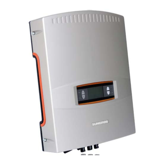
Product Appearance
Dimensions and Weight of Inverter
LCD Display Panel
DC Switch
Technical Description
Principle Description
Functions Description
3 Workflow about Inverter
4 Unpacking and Storage
Unpacking and Inspection
Identifying Inverter
Delivery Contents
Storage of Inverter
5 Installing Inverter Onto Wall
Selecting Installation Location
Moving Inverter to Installation Site
Installation Procedure
6 Electrical Connection
Terminals Description
Simplified Electrical Connection Diagram
Connecting Inverter to AC Grid
AC Side Requirements
Assembling AC Connector with Cables
Connecting Inverter to AC Grid
Connecting Inverter to PV Arrays
Assembling DC Cable to Connector
Wiring Procedures
PV System Grounding
Communication Connection
Communication Types
RS485 Communication Connection
7 Commissioning
Verify before Commissioning
Commissioning Procedures
8 Disconnection of Inverter
9 Troubleshooting
Troubleshooting of LED Indicator
Troubleshooting of Faults in LCD Screen
Maintenance
Cleaning the Cabinet
Cleaning the Heat Sink
Battery Maintenance
10 Operation of LCD Menu
Description of Button Function
Operation Mode of Inverter
Overview of Complete LCD Menu
The Default Screen
Contrast Adjustment
Current Running Information
Historical Information
Running Record
Fault Record
Language Settings
Time Settings
Deviation of E-Tot Adjustment
Load Default Settings
Firmware Version
Auto-Test (Only for Italy)
Running Parameters Settings
Protective Parameters Settings
Communication Parameters Settings
Address Settings
Protocol Settings
Inverter Start and Stop
Appendix
Electrical Specifications
Temperature Derating Curve
Exclusion of Liability
About Us
Contact Information
Advertisement
Quick Links
1
Connecting Inverter to Pv Arrays
2
Address Settings
Download this manual
SG2K5TL/SG3KTL/SG4KTL-31
PV Grid-Connected Inverter
User Manual
SG2K5_3K_4KTL-V31-UEN-Ver12-201206 Version: 1.2
Table of
Contents
Previous
Page
Next
Page
1
2
3
4
5
Advertisement
Table of Contents
Troubleshooting
Troubleshooting
53
Troubleshooting of Faults in LCD Screen
54
Need help?
Do you have a question about the SG2K5TL and is the answer not in the manual?
Ask a question
Questions and answers
Related Manuals for Sungrow SG2K5TL
Inverter Sungrow SG2K-S User Manual
Pv grid-connected inverter (72 pages)
Inverter Sungrow SG2K-S User Manual
Pv grid-connected inverter (83 pages)
Inverter Sungrow SG2K-S Quick User Manual
Pv grid-connected inverter (93 pages)
Inverter Sungrow SG2K5-S User Manual
Pv grid-connected inverter (79 pages)
Inverter Sungrow SG2K5-S User Manual
Pv grid-connected inverter (71 pages)
Inverter Sungrow SG2K-S User Manual
Pv grid-connected inverter (71 pages)
Inverter Sungrow SG2K-S User Manual
Pv grid-connected inverter (95 pages)
Inverter Sungrow SG2K-S User Manual
Pv grid-connected inverter (79 pages)
Inverter Sungrow SG2KTL-S User Manual
Pv grid-connected inverter (68 pages)
Inverter Sungrow SG2KTL-S User Manual
Pv grid-connected inverter (86 pages)
Inverter Sungrow SG20KTL User Manual
Pv grid-connected inverter (98 pages)
Inverter Sungrow SG15KTL-M Quick Installation Manual
(18 pages)
Inverter Sungrow SG5KTL-MT Quick Manual
3-phase pv inverters (5-20kw) commissioning with logger1000 (16 pages)
Inverter Sungrow SG250HX User Manual
Pv grid-connected inverter (78 pages)
Inverter Sungrow SG4.0RT User Manual
3-phase pv grid-connected inverter (133 pages)
Inverter Sungrow SG2.0RS-S User Manual
1-phase pv grid-connected inverter (99 pages)
This manual is also suitable for:
Sg3ktl
Sg4ktl-31
Table of Contents
Print
Rename the bookmark
Delete bookmark?
Delete from my manuals?
Login
Sign In
OR
Sign in with Facebook
Sign in with Google
Upload manual
Upload from disk
Upload from URL


Need help?
Do you have a question about the SG2K5TL and is the answer not in the manual?
Questions and answers